
20B NA BP semi-PP ITBs


Thread Starter
Full Member
Joined: Mar 2010
Posts: 129
Likes: 1
From: Australia
20B NA BP semi-PP ITBs
Hi guys,
Thought I would post what Im doing in here and see what you guys think. I am currently converting my S7 RS FD to a NA 20B.
It will be full Bridgeported and semi-PP and , I have designed an ITB setup for it, something similar to what I used to make for some IPRA cars here in Australia.
Basically it is 3X40mm primaries, 3X45mm secondaries, with the secondaries having a standoff injection setup, and also will be feeding the semi-PP.
With the throttle body I have designed, it will allow me to play around with trying mechanical secondaries.
The trumpets will also be carbon fibre (I used to work in advanced composites).
Im not sure how much this will help/(hurt?) driveability, but it gives me the flexability to try different linkages and try opening at different times.
I plan on also using injectors in the standard primary spots, so hopefully no issues with tip-in or down low.
The motor is getting lightened/balanced.
Here is the intake concept so far:

I was thinking of using the Bosch EV14 injectors, 6 X 550cc.
Does that sound appropriate to you guys?
Cheers,
Gaz
Thought I would post what Im doing in here and see what you guys think. I am currently converting my S7 RS FD to a NA 20B.
It will be full Bridgeported and semi-PP and , I have designed an ITB setup for it, something similar to what I used to make for some IPRA cars here in Australia.
Basically it is 3X40mm primaries, 3X45mm secondaries, with the secondaries having a standoff injection setup, and also will be feeding the semi-PP.
With the throttle body I have designed, it will allow me to play around with trying mechanical secondaries.
The trumpets will also be carbon fibre (I used to work in advanced composites).
Im not sure how much this will help/(hurt?) driveability, but it gives me the flexability to try different linkages and try opening at different times.
I plan on also using injectors in the standard primary spots, so hopefully no issues with tip-in or down low.
The motor is getting lightened/balanced.
Here is the intake concept so far:
I was thinking of using the Bosch EV14 injectors, 6 X 550cc.
Does that sound appropriate to you guys?
Cheers,
Gaz

i like it. admittedly, i can't bring much to the technical table in terms of critique or suggestions to your design, but i like it. it would seem logical that a port setup like that would require a completely custom intake system.
a couple questions though:
(1) why you went with a full bridge as opposed to a half-bridge?
(2) is this going to be primarily a track car?
(3) you mentioned playing with different opening times, are you going to idle off the peripherals? your design suggests not, but i kind of just wanted to put the bug in your ear.
Joined: May 2005
Posts: 2,745
Likes: 0
From: North Bay, Ontario
I've got two questions/suggestions for you,
1) I can't tell if there is the means to adjust intake length, but you should definitely allow adjustment in order to find what works for both the sideports and the peripheral port on the dyno.
2) Can you make 2 so I can have one as well? Looks amazing.
staged throttle linkage is something I am also going to be playing with on my 2-rotor semi-pp.
Looks good! Is that autocad 
Only thing I don't get is connecting the peripheral port runners with the secondary runners. I've seen cast manifolds like this, but I thought it was just because it's easier to fabricate. Why not go with 9 individual runners if you're going with an all-out custom intake manifold?
Only thing I don't get is connecting the peripheral port runners with the secondary runners. I've seen cast manifolds like this, but I thought it was just because it's easier to fabricate. Why not go with 9 individual runners if you're going with an all-out custom intake manifold?

Joined: Mar 2001
Posts: 31,857
Likes: 3,243
From: https://www2.mazda.com/en/100th/
i like! Mazda has an SAE paper with an engine like that, its a full PP with side ports. they use the PP as the primaries, and the side port as the secondary, and they didn't end up using it, but the performance looks like it would be really good (ve curve is like an rx8 but higher)
the thing that they DID play with is fuel injector location, they have a couple of different papers, but they always find that the best BSFC and response is with the injectors really close to the engine.
they also find that the power curve changes a lot with intake length, hence the variable length runners on the R26B, and 13J-MM
6x550 injectors would be perfect for an all out PP, i don't know about BP's.
i like! Mazda has an SAE paper with an engine like that, its a full PP with side ports. they use the PP as the primaries, and the side port as the secondary, and they didn't end up using it, but the performance looks like it would be really good (ve curve is like an rx8 but higher)
Trending Topics
Thread Starter
Full Member
Joined: Mar 2010
Posts: 129
Likes: 1
From: Australia
i like it. admittedly, i can't bring much to the technical table in terms of critique or suggestions to your design, but i like it. it would seem logical that a port setup like that would require a completely custom intake system.
a couple questions though:
(1) why you went with a full bridge as opposed to a half-bridge?
(2) is this going to be primarily a track car?
(3) you mentioned playing with different opening times, are you going to idle off the peripherals? your design suggests not, but i kind of just wanted to put the bug in your ear.
a couple questions though:
(1) why you went with a full bridge as opposed to a half-bridge?
(2) is this going to be primarily a track car?
(3) you mentioned playing with different opening times, are you going to idle off the peripherals? your design suggests not, but i kind of just wanted to put the bug in your ear.
2. This is my street car.
(although when Im finished with this, maybe not!)3. I was thinking to just idle off the primaries, and have those open first, then play around with the mechanical linkage to open the secondaries.
Last edited by F1Pilot; Nov 28, 2011 at 06:39 PM.
Thread Starter
Full Member
Joined: Mar 2010
Posts: 129
Likes: 1
From: Australia
I've got two questions/suggestions for you,
1) I can't tell if there is the means to adjust intake length, but you should definitely allow adjustment in order to find what works for both the sideports and the peripheral port on the dyno.
2) Can you make 2 so I can have one as well? Looks amazing.
staged throttle linkage is something I am also going to be playing with on my 2-rotor semi-pp.
1) I can't tell if there is the means to adjust intake length, but you should definitely allow adjustment in order to find what works for both the sideports and the peripheral port on the dyno.
2) Can you make 2 so I can have one as well? Looks amazing.
staged throttle linkage is something I am also going to be playing with on my 2-rotor semi-pp.
2. Well I need to make it a reality first! But thanks!!
Last edited by F1Pilot; Nov 28, 2011 at 06:40 PM.
Thread Starter
Full Member
Joined: Mar 2010
Posts: 129
Likes: 1
From: Australia
Looks good! Is that autocad
Only thing I don't get is connecting the peripheral port runners with the secondary runners. I've seen cast manifolds like this, but I thought it was just because it's easier to fabricate. Why not go with 9 individual runners if you're going with an all-out custom intake manifold?
Only thing I don't get is connecting the peripheral port runners with the secondary runners. I've seen cast manifolds like this, but I thought it was just because it's easier to fabricate. Why not go with 9 individual runners if you're going with an all-out custom intake manifold?
Good point. The design was first coming together as just a 6 runner for the BP. I then looked into semi-PP and it got me all worked up!lol.
I agree that it would definately be better to separate them, however Im not sure about the room and extra cost. As it is, I managed to get the throttle body fairly short and not very tall, so it will fit under bonnet with an airbox quite well.
Semi-PP was an after thought but I might look into whether I can squeeze in an extra 3 somewhere!!
Thread Starter
Full Member
Joined: Mar 2010
Posts: 129
Likes: 1
From: Australia
That was my thinking with the injectors. While driving under say 50% throttle only the primary runners and injectors will be operating, however over 50% (which will probably mean 100%), the standoff injectors will come on.
Im hoping this combo will make it as good as it can be to drive when not WOT, but give good results at WOT.
Yes the rotors are getting done right now. The whole rotating assembly will have approx 1.2KG removed and will be balanced, so hopefully no problems with the revs.
Im hoping this combo will make it as good as it can be to drive when not WOT, but give good results at WOT.
Yes the rotors are getting done right now. The whole rotating assembly will have approx 1.2KG removed and will be balanced, so hopefully no problems with the revs.
Last edited by F1Pilot; Nov 28, 2011 at 06:41 PM.
Joined: Mar 2001
Posts: 31,857
Likes: 3,243
From: https://www2.mazda.com/en/100th/
Mazda had a race engine in the 70's that was like this except the side ports were the primaries and the p-ports came online later. It only made 2 more hp than their standard side port race engines of the day so they scrapped them. I'm sure average power was different but we were talking about carbs back then and I'm sure they were more difficult to tune than their other engines.
the insert + manifold = the exhaust box/chamber that you've talked about. so the concept works
Joined: Mar 2001
Posts: 31,857
Likes: 3,243
From: https://www2.mazda.com/en/100th/
Yes this is AutoCAD2010.
Good point. The design was first coming together as just a 6 runner for the BP. I then looked into semi-PP and it got me all worked up!lol.
I agree that it would definately be better to separate them, however Im not sure about the room and extra cost. As it is, I managed to get the throttle body fairly short and not very tall, so it will fit under bonnet with an airbox quite well.
Semi-PP was an after thought but I might look into whether I can squeeze in an extra 3 somewhere!!
i'm still working on my semi-peripheral 13B when i can. thoughts and designs cost nothing, so i keep at it even though i'm not buying or building anything at this time. however, separating all the ports and adjusting lengths makes the most sense and Logan is proving that.
there are a few people in this circle of semi-pp engines, but we're growing. you should reach out. so far the ones i've contacted are pretty cool about advice and help.
I can tell you did your homework with your beautiful design. Nice radius bends, long primary and shorter secondary runners to allow for a long torque curve.  I also like the thought of having secondary control. Understand though, that delayed secondary control only works when you have no overlap with the side ports.
On stock engines, the primary ports are the primary source of flow in the low range/off throttle. Mazda knows that this keeps the air velocity with-in the primary runners very high so the combustion chamber fills more fully in light loads. The more air you can cram into the combustion chamber for any given rpm range, the larger the explosion potential during the combustion event. This of course you know is what allows the engine to make more torque (something I'm sure you already knew). So since your gonna be running a full bridge, your gonna loose that low range flow velocity out your exhaust because of all that overlap. So regardless if you have secondary control or not your overlap is what's gonna make delaying the secondary's almost pointless in your application. Don't get me wrong, I'm not trying to persuade you in not doing the delayed secondary control. Just making a point I feel to be valid.
Now since your gonna be merging the semi PP with the secondary runners, I would run a larger runner. The last thing you want is the air flow slowing down as it enters that divided section. If anything the air flow should be speeding up their.
Are your runners gonna be made out of carbon fiber? If so, you have the freedom to start large at the throttle plate while tapering down towards the block for added velocity.
I also like the thought of having secondary control. Understand though, that delayed secondary control only works when you have no overlap with the side ports. On stock engines, the primary ports are the primary source of flow in the low range/off throttle. Mazda knows that this keeps the air velocity with-in the primary runners very high so the combustion chamber fills more fully in light loads. The more air you can cram into the combustion chamber for any given rpm range, the larger the explosion potential during the combustion event. This of course you know is what allows the engine to make more torque (something I'm sure you already knew). So since your gonna be running a full bridge, your gonna loose that low range flow velocity out your exhaust because of all that overlap. So regardless if you have secondary control or not your overlap is what's gonna make delaying the secondary's almost pointless in your application. Don't get me wrong, I'm not trying to persuade you in not doing the delayed secondary control. Just making a point I feel to be valid.
Now since your gonna be merging the semi PP with the secondary runners, I would run a larger runner. The last thing you want is the air flow slowing down as it enters that divided section. If anything the air flow should be speeding up their.
Are your runners gonna be made out of carbon fiber? If so, you have the freedom to start large at the throttle plate while tapering down towards the block for added velocity.
Rotary Enthusiast


Joined: Aug 2004
Posts: 1,326
Likes: 9
From: Australia - Perth
look great I have a LIM all done up in cad for a Semi PP design as well to bolt to a stock 13bre UIM.
Love to know more details how you make the thing out of Carbon fiber looks bloody complex !!
PS, your a Aussie, come join us on Ausrotary
I have a LIM all done up in cad for a Semi PP design as well to bolt to a stock 13bre UIM.Love to know more details how you make the thing out of Carbon fiber
looks bloody complex !!PS, your a Aussie, come join us on Ausrotary
Thread Starter
Full Member
Joined: Mar 2010
Posts: 129
Likes: 1
From: Australia
T-Von, yep you make great points there, and this is pretty much what I would expect to happen with the bridge. The great thing about having the two shafts above each other like that, is that to muck around with staging the throttles, all I need to do is change the linkages to different sizes etc.
But yes, Id agree that I dont think it will do much, but it will be interesting to see, maybe it will make it a bit quiter on the under 50%? I really dont know.
Do you think that 45mm is too small for secondaries and semi-PP? The PP will only be 25mmID.
Also can we post links to other forums on here?
Thread Starter
Full Member
Joined: Mar 2010
Posts: 129
Likes: 1
From: Australia
I wish I was making it all out of carbon! But sadly no, just the trumpets. I do know how to make it out of carbon and really if I wanted, I could mould this when its made to make carbon.
Granted if I did the OD of the pipe would become the ID, but it could be done.
Somehow I couldn't really justify spending the same money on a mould that the whole engine cost me! lol
Granted if I did the OD of the pipe would become the ID, but it could be done.
Somehow I couldn't really justify spending the same money on a mould that the whole engine cost me! lol
Thread Starter
Full Member
Joined: Mar 2010
Posts: 129
Likes: 1
From: Australia
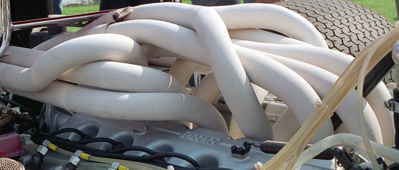
Bit of header mucking around:
If someone could measure the room between the exhaust face and the chassis rail, that would be awesome, as I have no idea how much room I have to work with there.

If someone could measure the room between the exhaust face and the chassis rail, that would be awesome, as I have no idea how much room I have to work with there.
If this is going to be your "street" car, I would just street port the primaries and bridge port the secondaries. Like you already said, you could mess around with the bell cranks on the TBs to allow the secondaries to open up at a higher throttle position to aid in drivability.
45mm is just a hair over 1-3/4" (1.77") and the same diameter as the stock 20b lim at the upper flange. If you take tubing that size and shape it to the 20b's already large secondary ports, you will find that that size runner is a perfect flow match to the secondarys on the block. I know this because that's what I used for my secondary runners on my built from scratch intake for my own 20b. You however are gonna be running a bridge port on the back end of that runner and also feeding a small PP. Do you now still feel it's large enough?
Either way since your not planining on having adjustable runner lengths to maximize your torque peak location, you can experiment with different size runners to change the flow velocity and move the torque peak.
Example! If I were doing this project with your design, I would flange those secondary/semi PP runners so I could change them out with either smaller diameter or larger verisons of the same design. This would be the best of both worlds for you because both sizes would be usable. You could tune the engine for the smaller diameter versions for street and the larger versions for race.
Thread Starter
Full Member
Joined: Mar 2010
Posts: 129
Likes: 1
From: Australia
True. Yes I measured the circumfrence of the secondary port and as you say, it is very close to the 45mm size.
Do I think they are big enough? Well, real world example, my old race PP originally had large runners, we decided to try smaller runners and the engine made exactly the same peak HP but picked up a bunch of power mid range. Im talking like 20HP at the wheels at some points.
End result=faster lap times, same peak HP.
The sad thing is, I have been told from a very reputable builder, that these ports actually flow quite poorly compared to non-cosmo (in NA that is). So, that is a bit sad but Im sure it wont worry me too much considering its application.
Either way, I can't wait to see the finished results. I forgot on your exhaust clearance. The clearance all depends on your positioning. In the fd the stock 13b is offset towards your passenger side (drivers side for us) giving you more room for the factory twins. If you center the 20b you will have about 8" to the rail. Hope that helps.