
Megasquirt Stabbing CAS stuff

Stabbing CAS stuff
Ok, i know the procedure for stabbing it in stock configuration (11,1,5,7), but Id like to run the engine (S4 TII) with 1,3,7,9 timing. I searched for CAS stab in here, but find anything clear enough that Id want to try without asking first. My question is this:
Looking down the CAS from the top (black cover), which direction should I turn the CAS shaft, clockwise or counterclockwise, to go from stock configuration to 1,3,7,9 config? I should be turning it two teeth (on the 24 tooth wheel) in that direction, yes?
When stabbing, I line up the yellow mark (5* ATDC) on the main pulley with the pin, line up the CAS as above, then would the settings in the spark menu be?
Trigger angle = 60
Cranking Advance Angle = 0
Trim Angle = -5
Is this correct? I dont have the engine or CAS in front of me right now, so im trying to do this from memory. Thanks!
MegaSquirt Mod
Joined: Sep 2004
Posts: 4,721
Likes: 1
From: Maryland
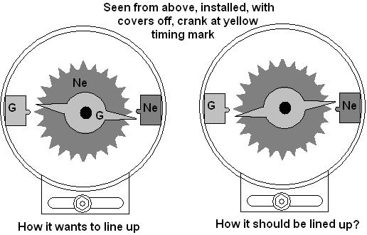
To stab the CAS with 1,3,7,9 settings, open the CAS, and look at the teeth... with the Ne VR sensor facing away from you, line the CAS up on the first tooth to the right of the G sensor, and stab it.
The settings should be:
Trigger angle = 60
Cranking advance = 0
Trim angle = 0
Then to fine tune your timing, set the fixed angle to -5, and line up the yellow mark on the e-shaft pulley with a timing light. Then set fixed angle back to -10 and you're good to go!
Ken
The settings should be:
Trigger angle = 60
Cranking advance = 0
Trim angle = 0
Then to fine tune your timing, set the fixed angle to -5, and line up the yellow mark on the e-shaft pulley with a timing light. Then set fixed angle back to -10 and you're good to go!
Ken
Ok, im going to go pick up a timing light today to fine-tune it, but i was having trouble getting the cas to line up with the first tooth to the right of the g sensor. I would get it lined up that way, but it would not slide in when the engine was at 5* atdc. if it did slide in, the curvature of the teeth would push the toothed wheels so that it was lined up on the left side, so that it was lined up one tooth counterclockwise (if i'm interpreting left and right the same way you are). hopefully this picture will clarify
Full Member
Joined: Aug 2005
Posts: 179
Likes: 0
From: LA, CA
I'm not sure how far off the -5 leading mark would make the cas move, but I would presume not too much ... (although the actual stab procedure does make it move quite a bit)
I just verified this the other day for another forum member (I also use the 1 3 7 9 settings) ... with the RB pulley which has -10 0 10 20 marks on it, at 0 the 3rd ne tooth past the g signal tooth lines up pretty close to the g sensor (if you are looking straight down on it).
HTH
I just verified this the other day for another forum member (I also use the 1 3 7 9 settings) ... with the RB pulley which has -10 0 10 20 marks on it, at 0 the 3rd ne tooth past the g signal tooth lines up pretty close to the g sensor (if you are looking straight down on it).
HTH
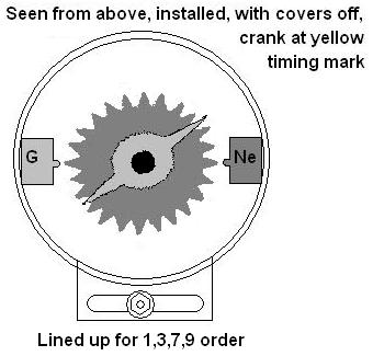
yea, i sat down and drew it out and came to the 3rd tooth conclusion as well. Heres another diagram, just so if people search and find this, theres a correct picture as well.
Just to chime in with a similar question but using a modified CAS. To stab for 1, 3 ,7 ,9
the third tooth after the missing tooth on the 24 tooth wheel would be correct?
I Hope.
the third tooth after the missing tooth on the 24 tooth wheel would be correct?
I Hope.
Trending Topics
yea, it shoudl end up pointing to the third tooth after the missing one (as long as you're using a 60* trigger angle).
I got lazy and didnt want to work it out before, but now that I did its just as easy as the CBR600 bike engine I did a few months ago
I got lazy and didnt want to work it out before, but now that I did its just as easy as the CBR600 bike engine I did a few months ago
Many thanks!
nope, the yellow one is at 5* ATDC, and the red one is at 20* ATDC (IIRC). The CAS wheel rotates once every two e-shaft rotations, so 12 teeth pass for every one e-shaft revolution. one tooth is then equal to 30* of the e-shaft's rotation, so at 20* you are 2/3 of the way from the last picture shown above and the next tooth.
So the NE sensor should be 2/3 of the way between the 3rd and 4th tooth of the 24 tooth wheel when the pulley is lined up at the red mark (labelling the tooth right after the G sensor tooth #1, and continuing clockwise). Before stabbing, you should be able to line it up at the 3rd tooth, it will move a little when you put it in. Then once its in, try to position it 2/3 of the way between teeth 3 and 4. This should be close enough to get it exact with a timing light.
So the NE sensor should be 2/3 of the way between the 3rd and 4th tooth of the 24 tooth wheel when the pulley is lined up at the red mark (labelling the tooth right after the G sensor tooth #1, and continuing clockwise). Before stabbing, you should be able to line it up at the 3rd tooth, it will move a little when you put it in. Then once its in, try to position it 2/3 of the way between teeth 3 and 4. This should be close enough to get it exact with a timing light.
First mark on pulley is 5ATD and second is 20ATD correct? there is no paint markings on my pulleys.
Now looking at your pic Topless, the first tooth AFTER the G sensor tooth is stabbed going clockwise, and the 3rd tooth should then be positioned as you said once reinstalled and the pulley lined up at the red marking (20ATD) for 1, 3, 7, 9 timing?
EDIT: Topless, are you running a second VR conditioner or a removed tooth setup on the CAS? Im thinkin I got the wrong idea of what your trying to say here. Im running toothless, but have not removed the teeth yet.
Yea, if there are no marks, then the first one (first to pass the pin as the engine is rotating) is 5* ATDC and the second is 20* ATDC for rotor 1.
oh, im running the second VR sensor, so i was showing the cas as it appears with both wheels. It should be stabbed as shown in the third picture in the thread, not the first two. So the third tooth after the G sensor is how it should be stabbed.
Since you're running toothless, when the engine is set at about TDC (you can estimate based off of the marks where this would be, and just get close enough, thats what the timing light is for), you would line up the 3rd existing tooth after the missing one with the NE sensor and stab it to use 1,3,7,9 settings with a 60* trigger angle
so it really does not matter what 2 opposing teeth we remove off the bottom wheel, just as long as when we stab the CAS, the 3rd tooth from the removed is TDC I assume from reading all the different threads about it.
I think once Im done with this and get it all running, and with Ken and Renns permissions, Im gonna TRY to put at least the tooth removal and stabbing into a very simple explanation so people dont search and see the different threads with pretty much the same info but spread out so much.
Topless, thanks much for helpin me out with this. Between you T2GTUs, Renns, and ken, Im finally gonna get this puppy fired up very very soon.
yea, as long as the teeth removed are opposing, it will be fine. The MS would start counting at the gap in teeth, run 1 thru 11, hit the next gap, and restart. Since its only that bottom sensor (the Ne sensor) thats counting now, which specific teeth are removed doesnt make much of a difference as long as they're properly synched with the e-shaft.
In fact, if you really felt like it, you could remove the whole 2-tooth wheel and G sensor after (or before) grinding off the teeth, but its not really going to accomplish much (besides what, like, 3 grams of weight savings?)
In fact, if you really felt like it, you could remove the whole 2-tooth wheel and G sensor after (or before) grinding off the teeth, but its not really going to accomplish much (besides what, like, 3 grams of weight savings?)
Joined: Aug 2005
Posts: 795
Likes: 0
From: Va Beach or IN, indianapolis
hey guys when you stab the CAS , which is easyer to run a stock turbo2 car? ive had my car running before all this and the CAS is set to where it ran the new motor in it . but is it ok to run 1,3,7,9 first hand ?? i want to run a single vr signal .
Rotary Enthusiast
Joined: Mar 2007
Posts: 1,485
Likes: 0
From: Pasadena
Sorry to b such a newb, but Im trying to get my engine timed for STOCK timing. I downloaded the manual form rx7city and its not very specific. It says to line crank pulley to yellow mark, but I dont have any colors.
Which mark is the "yellow" mark? The first or second mark when I turn clockwise?
After that, I just line up the mark on the cas with the grove on the gear and drop it in? What woiuld cas look like if i took off the cover? Hope you guys can help, thanks
Which mark is the "yellow" mark? The first or second mark when I turn clockwise?
After that, I just line up the mark on the cas with the grove on the gear and drop it in? What woiuld cas look like if i took off the cover? Hope you guys can help, thanks
as the pulley engine turns clockwise (facing it from the front), the 5* ATDC mark will be the first one to pass the timing pin sticking out. I dont remember what it looks like when the external marks are lined up... just pull of the cover, line up the marks, and take a look.
Ok, I tried stabbing my CAS and I'm not sure if I did it right. I'm setting it up to run 1, 3, 7, 9 timing. I lined up the first mark on the eccentric shaft pulley with the pointer on the front cover, then dropped the CAS in. But the only way to line up the sensors with the 3rd tooth after the missing one is to rotate the CAS all the way. I attached a pic of how its currently installed. Is this right?
Mine ended up right in the middle. Is your main pulley at the 5*ATDC or at 0*? It should be lined up at 0*, but there are only marks for 5* and 20* ATDC, so you kinda need to estimate, and then get it spot-on with a timing light. The CAS seems to be correct, unless the fore-shortening and perspective is screwing with my eyes.
Mine ended up right in the middle. Is your main pulley at the 5*ATDC or at 0*? It should be lined up at 0*, but there are only marks for 5* and 20* ATDC, so you kinda need to estimate, and then get it spot-on with a timing light. The CAS seems to be correct, unless the fore-shortening and perspective is screwing with my eyes.
yea, that would be slightly (1/3 of the distance btwn the two marks) clockwise from the first (yellow, 5*) mark when facing the engine. You still need the timing light to fine-tune it, but this will get you pretty close. I ran my engine for about a month before I found the timing light, and just to make sure I wasnt off and going to detonate, I pulled about 5* of timing from the high load portions of the spark map. Once i had the timing set, i could add those back in.