Megasquirt Problems upgrading to MS2
 07-20-08, 04:23 PM
#1
Problems upgrading to MS2
Ok, I decided to try to switch to MS2-E, V1.0.2, and have run into a few problems.
First, I brought 12v power to JP9, and moved the 2nd VR circuit output from JP8 to JP10.
Then, using a Jimstim board for power, I tried installing the firmware to the MS2. It seemed to go well until I got an odd error (but it didnt stop the firmware installer). The error was:
Opened comm port 4 at 115200.
ERROR: Unknown error status response, e=0x00
Boostrap loaded...
.
.
5. Turn off Megasquirt
Press any key to continue...
Since the installer continued to run properly, I figured that it had worked despite the error. At the end of the installer it read:
Reading ms2_extra.s19:
ms2_extra.s19
Detected MS-II (HCS12) code.
Entry point: 0xc00
Code range" 0x4000-0x3db4b0
File read successfully.
Opened comm port 4 at 115200.
ERROR: Unknown error status response, e=0x00
After this, megatune acts weirdly.
-If I start megatune with the MS2 on, the window pops up asking which configuration I want to use, and after selecting the MS2 configuration I set up, megatune freezes.
-If I start megatune with the MS2 off, it will start normally, but as soon as I turn the MS2 on, it freezes.
-If I start megatune with the MS2 on, select the configuration, and when it appears frozen, I turn off the MS2, I get an error saying
"Controller code version does not match signature in MegaSquirt-II.ini
(See audit.log for where the above file was found.)
Expected "MS2Extra REL 2.0.0" (found in ini file)
Recieved "" (from controller)"
Help! (Thanks)
 07-23-08, 09:53 PM
#2
OK, here some Info which you may or may not be aware of.
AFAIK
MS1-extra JS8 is for 2nd trigger input.
MS2-extra 1.02 JP4 is for 2nd trigger input.
MS2-extra 2.0.x JS10 is for 2nd trigger input.
Ken also suggested using the zero crossing mode of the LM1815N with 2.0.x, it works in zero crossing mode on MS2-extra 1.0.2 as well as MS1 extra.
I had lots of problems with that stuff that you are having. I found that my serial port wasn't very good in my laptop.
I'm sure you already know this, but make sure you run the copyini.bat file to put the right ini file in megatune before you load.
Say you flash to MS2-extra 2.0.1 or whatever the current version is, make sure you run the copyini inside the same directory.
One thing you can try is to drop the BAUD rate down to 19200 in Device properties, and set the value in megatune, followed by a close of megatune and a reboot of the megasquirt.
EDIT:
AND its SC12+ to JS9 not JP9, if there even is a JP9
07-24-08, 10:18 AM
#3
MegaSquirt Mod
It sounds to me like the firmware update failed... if it was a new ms2, you need to use the boot jumper the first time you install the firmware. If you're still getting errors when you use that, then you may need to use the options that adjust the serial port timing while loading the firmware.
07-24-08, 02:30 PM
#4
I meant JS8, JS9, JS10... I just messed up the letters.
I had been using the boot jumper to try to load the firmware. I'll try to lower the baud rate, and reinstall all the 2.0.x stuff and put the LM into zero-crossing mode later tonight if all goes well/quickly on the other stuff im doing tonight. I have switches on the 2nd VR and power lines so I can switch between MS1 and MS2 (2.0.x, i dont have anything running to JS4).
I had been using the boot jumper to try to load the firmware. I'll try to lower the baud rate, and reinstall all the 2.0.x stuff and put the LM into zero-crossing mode later tonight if all goes well/quickly on the other stuff im doing tonight. I have switches on the 2nd VR and power lines so I can switch between MS1 and MS2 (2.0.x, i dont have anything running to JS4).
07-25-08, 02:14 PM
#5
MegaSquirt Mod
Don't lower the baud rate, the ms2 bootloader only supports 115200. I'm talking about when you use the .bat file that comes with the firmware to upload it to the MS, there are debug options to increase the amount of time between commands to the MS. You should use those.
I'm confident that your whole problem is that the firmware did not load correctly.
Ken
I'm confident that your whole problem is that the firmware did not load correctly.
Ken
08-04-08, 12:54 PM
#7
I went back to MS1 for a little while since a few other things on the car popped up that needed attention, so I didnt have the time I wanted to devote to getting it to work properly. I'm planning on giving it another shot in september, after I do an auto-x and another 1200 mile trip (since I've gotten the MS1 pretty well tuned for the time being and dont want to run into teething troubles during either of these).
Trending Topics
11-01-08, 08:27 PM
#8
Ok, trying MS2extra 2.0.1 again. This time the bootloader seems to be working fine, and since moving the correct *.ini file into the megatune directory, megatune is connecting to the MS. That being said, there are some difficulties I'm running into just using the jimstim.
First: using the JimStim on the MS1 chip (029y4) works for MAT, CLT etc, but the RPM simulator for the nippon-denso output does not. I have all of the switches down except for #5, which is what it tells me to do here. I've tried it with the 5v pull-ups connected and disconnected, didnt seem to make a difference.
Second: For MS2, not only does the RPM portion of the JimStim not work, but none the ***** work. I just have the built-in curves for the temperature sensors loaded up, but those dont seem to change anything. The only signs of life are the FIDL LED on the JimStim and D14 and D16 on the V3.0 board being lit. I followed the settings in H4Inf's MS2 V3 CAS writeup for the wheel input settings (I had been running the MS1 1-3-7-9 settings). I'm going to double-check that my LM1815 is wired up the same way, but I think that it is.
I had a few general MS2extra questions too.
-There seemed to be a couple differences in the menus H4Inf had screen shots of there, but i'm assuming thats just due to updates of the code.
-The tables are listed with % as the y-axis... does this refer to MAP in KPa as MS1 does, or is this different?
-Is there a difference between leaving the link between TSEL and VROUTINV using falling edge and changing the link to TSEL to VROUT using rising edge?
Thank you very much, I hope to get this running on MS2 soon!
11-02-08, 01:09 AM
#9
A quick addendum to the above; i've gone through and made sure that all of the temp sensors and TPS were calibrated and sent to the MS, but still none of the temp sensors respond. TPS will read between 0% - 1.4% based on the pot, but thats the only response to the jimstim I'm seeing
As for the comparison of 2nd VR sensor circuits, mine is the same as H4Inf's except i have a 330Z resistor between VR2 and ground, and the resistor inline with OUT2 looks to be either 10kZ or 18kZ. Other than that they look to be the same.
As for the comparison of 2nd VR sensor circuits, mine is the same as H4Inf's except i have a 330Z resistor between VR2 and ground, and the resistor inline with OUT2 looks to be either 10kZ or 18kZ. Other than that they look to be the same.
11-02-08, 09:39 AM
#10
One more addition (sorry, i'm posting as I play around with it)
-All of the temperatures are staying at -18*C, regardless of their pots
-The TPS ADC ranges from 0 to 1022, but even calibrated this way it only corresponds in megatune to 0-1.4%
-I get a "Controller voltage too low for reliable FLASH burning. Try anyway?" error message, even though I'm feeding the JimStim 13v, see 5v even between the sources at the top of the proto board, and 11v (not 12v) between ground and the leftmost pin of U5.
This is really starting to confound me.
11-02-08, 10:31 AM
#11
Back at it again!!
iTrader: (3)
Join Date: Jun 2003
Location: Western Colorado
Posts: 1,324
Likes: 0
Received 0 Likes
on
0 Posts
One more addition (sorry, i'm posting as I play around with it)
-All of the temperatures are staying at -18*C, regardless of their pots
-The TPS ADC ranges from 0 to 1022, but even calibrated this way it only corresponds in megatune to 0-1.4%
-I get a "Controller voltage too low for reliable FLASH burning. Try anyway?" error message, even though I'm feeding the JimStim 13v, see 5v even between the sources at the top of the proto board, and 11v (not 12v) between ground and the leftmost pin of U5.
This is really starting to confound me.
-All of the temperatures are staying at -18*C, regardless of their pots
-The TPS ADC ranges from 0 to 1022, but even calibrated this way it only corresponds in megatune to 0-1.4%
-I get a "Controller voltage too low for reliable FLASH burning. Try anyway?" error message, even though I'm feeding the JimStim 13v, see 5v even between the sources at the top of the proto board, and 11v (not 12v) between ground and the leftmost pin of U5.
This is really starting to confound me.
I had the EXACT same results when I tried using 2.0.1. Thats' why I tried 1.0.2, but I was having too many consistent corruption problems
 I will be following this closely as I have an ms2 chip just sitting in a box in my room, and I can't use it until someone is having success with it and can help others along with getting it to work.........however, the best would be if there will be an eventual writeup/ procedure on getting the 2.0.1 (or eventually newer code) to work, and what will need to be changed in the proto area as compared to ms1 lm1815 setup on there
Last edited by 2Lucky2tha7; 11-02-08 at 10:33 AM.
11-02-08, 11:28 AM
#12
I'm thinking (fearing, worrying) that it may be the MS2 processor itself that is having the problem. I took all the care I could to keep it away from static, in original packaging, and to not handle it unless completely necessary, but I really dont know. I may try to order another one to rule that out if nothing else works out.
I posted the same thing up on the msextra.com forums here:
http://www.msextra.com/viewtopic.php?f=101&t=29762
I posted the same thing up on the msextra.com forums here:
http://www.msextra.com/viewtopic.php?f=101&t=29762
11-02-08, 02:03 PM
#13
Back at it again!!
iTrader: (3)
Join Date: Jun 2003
Location: Western Colorado
Posts: 1,324
Likes: 0
Received 0 Likes
on
0 Posts
The one I originally got was already installed as I bought the MS2 3.0 setup from DIY, and I used a grounding strap on my wrist the whole time I was handling and modifying the board, so personally, I would rule that out because you are getting the same results I did with the 2.0.1 setup. When I re-modified the proto area, etc., for the 1.0.2 setup, I was able to get the car to run for a very short time (a matter of minutes) and even back down the driveway and drive back up, but then all the values got corrupted on the screen and required reflashing.
I mean, you can buy another ms2 processor if you really want to, but it is another $90+S&H.......and you may still have the same problem.......
I mean, you can buy another ms2 processor if you really want to, but it is another $90+S&H.......and you may still have the same problem.......
11-02-08, 03:28 PM
#14
well, i think i've gotten that problem solved. (although i'm still curious about the questions)
I did a bunch of reading thru the MS2e section at msextra.com, and saw that there had been a couple problems due to corrupted firmware in the bootloader or something, and that by downloading the MS2 package from elsewhere solved that problem. Just to rule it out, i dl'ed the package from http://www.msextra.com/viewtopic.php?f=101&t=28357, loaded it up, and then it worked. It would stop working if I loaded the msq that i had been working on previously, so I started from scratch and it seems to be all good.
That being said, now i'm having all sorts of sync errors when its on the car, so figuring those out is the next step. I have a spare CAS and a drill to play around with, and ordered the components to make another LM1815 circuit to play with instead of messing around on the proto area, so we'll see if we can get this figured out.
11-02-08, 05:46 PM
#15
That being said, now i'm having all sorts of sync errors when its on the car, so figuring those out is the next step. I have a spare CAS and a drill to play around with, and ordered the components to make another LM1815 circuit to play with instead of messing around on the proto area, so we'll see if we can get this figured out.
Maybe sticking the LM1815 into 'mode2" and adjusting the cas pickup very close may have an effect,give it a shot? Heck,even dig out the "ouija board" to exercise the poltergeist hiding in the second trigger.

You probably saw these threads in the MSextra site?
http://www.msextra.com/viewtopic.php?f=91&t=29551
http://www.msextra.com/viewtopic.php?f=91&t=29669
11-04-08, 12:15 PM
#16
I'll be giving it a shot, as well as playing with the idea of putting the transistor and pull-up resistor in line with the LM1815 output. I was also looking at the low impedance noise discussion in the MS2e forums, and will need to do that anyway, so I'll see what effect that has.
Has anyone used any of the software that turns your computer's microphone input into an oscilloscope? I'm looking for suggestions, since this is the one piece of equipment I dont have (although may be able to borrow).
Lastly, can anyone shed some light on the following questions?
-Is there a difference between leaving the link between TSEL and VROUTINV using falling edge and changing the link to TSEL to VROUT using rising edge?
-Is the "Tooth 1 angle" in trigger wheel settings measured in crank degrees or degrees of the sensor (dependant on "wheel speed")
Thanks a lot!
11-04-08, 01:52 PM
#17
The other two guys couldn't get 2.01 to work right either(Jobro, Gross Pollluter) and reverted back to 1.02.
Maybe sticking the LM1815 into 'mode2" and adjusting the cas pickup very close may have an effect,give it a shot? Heck,even dig out the "ouija board" to exercise the poltergeist hiding in the second trigger.
You probably saw these threads in the MSextra site?
http://www.msextra.com/viewtopic.php?f=91&t=29551
http://www.msextra.com/viewtopic.php?f=91&t=29669
I haven't tried 2.1.0 pre release yet which has an important rotary fix regarding cranking and low rpm (below 600rpm or so). I will get around to trying the new code one day but I'm not convinced it will fix the problems of random misfires everywhere in the rev range. The guys are working on the 2nd trigger noise filter which I am skeptical about.
11-04-08, 04:02 PM
#18
Senior Member

Join Date: May 2002
Location: FL
Posts: 386
Likes: 0
Received 0 Likes
on
0 Posts
Yes, I'm back to using 1.02 with missing tooth (12-1) CAS. I'm sure Ken will get it straightened out with code and/or someone else will have a definitive solve for the 24+2/2.0.1 situation using a mode of the 1815 soon. I would love to extensively experiment but the car is getting a turbo transplant at the moment along with freshening of most of the coolers and cleanup of all the underhood stuff including a self fabbed sidemount alternator setup. I'm an early retiree from one career heading for a second career with a 15 hour classload (nothing like being a 49 year old 20 year old!!!) so am a little shy on the massive spare time I had in the past though still have plenty! Progress reports to follow.
-Mike (aka mike_robert on the MS forums)
-Mike (aka mike_robert on the MS forums)
11-05-08, 02:13 AM
#19
Yes, I'm back to using 1.02 with missing tooth (12-1) CAS. I'm sure Ken will get it straightened out with code and/or someone else will have a definitive solve for the 24+2/2.0.1 situation using a mode of the 1815 soon. I would love to extensively experiment but the car is getting a turbo transplant at the moment along with freshening of most of the coolers and cleanup of all the underhood stuff including a self fabbed sidemount alternator setup. I'm an early retiree from one career heading for a second career with a 15 hour classload (nothing like being a 49 year old 20 year old!!!) so am a little shy on the massive spare time I had in the past though still have plenty! Progress reports to follow.
-Mike (aka mike_robert on the MS forums)
-Mike (aka mike_robert on the MS forums)
11-07-08, 10:32 AM
#20
MegaSquirt Mod
there was a problem at very low revs with 2.0.x. 2.1 solves that problem.
I'm currently running 2.1 with no issues with that fix. I've driven it maybe 20 miles on 2.1.
I need to fix my brakes before I take it back out again though, as they're barely working.
i'm also working on 2nd trig noise filter/false trigger protection which should clean up any remaining problems with 2.x.x for those who still have problems with the latest 2.1 beta.
Ken
11-08-08, 07:33 PM
#21
Ok, at this point, i'm pretty confounded. I've tried using both outputs 10 and 12 with a transistor after 10 to get it to high=true and a 4.7kZ pull-up on 12, and they both seemed to act the same way, and exactly as they should. I've tried using the RC circuit on 14 with one-shot to change the width of the output pulse, or just hooking it to ground and enabling zero-crossing.
The G+ signal seems to be working perfectly, the problem is with getting it to sync. That brings me to my first question: What the code check to maintain sync?
If i changed the settings in megatune to a 12 tooth cam wheel, it had no problems remaining synced, it just read double the actual speed. This lead me to believe that it was not counting all of the teeth on the NE wheel (which it seems to be when scoping the output at tsel). It seemed to fall out of sync proportionally to the CAS speed, which also implied counting problems.
All of the signals i've been seeing have been very clean, no mis-triggers of the LM1815, and solid 0-5V square-waves. All of the hardware seems to be performing fine, its just not maintaining sync.
EDIT: i did download the 2.1 beta and install it, but there may be an issue with the filtering. Under Advanced Ignition Options, I can select any of the filtering methods, but none of the variables below them become unshaded or modifiable.
11-08-08, 11:59 PM
#23
I keep coming back to this thing after the edit option is gone...
Anywho, I've been thinking that the trigger wheel teeth number should be 12 for cam wheel (6 for crank wheel), even though this seemed to be giving me double the RPM than the engine should have been cranking at in megatune (although somehow the trailing-spark based tach was still correct)
This is because only 12 Ne teeth pass between each G tooth, which would explain my sync error that always manifests itself, regardless of what i'm doing with the 2nd trigger. Physically, this also makes sense, since 12 teeth pass the sensor over the course of one full 4-stroke cycle of rotor 1. However, since the full 4 strokes are happening over just one eccentric shaft rotation instead of two crank rotations, and we're getting two combustion events over those 360*, we need to set the engine as a two-stroke, 2 cyl engine under "engine constants".
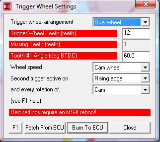
Following that, since the number of cyls is set to 2, the engine type is even-fire, and the tooth #1 angle is 60* (360*/12 teeth, X 2 teeth since tooth #3 is at TDC), then it should follow that the MS will know that 60* after tooth #1 (so tooth #3) will be TDC firing for rotor 1, then TDC firing for rotor 2 would be at an even spacing of 180* + 60* = 240* (aka tooth #9). This would match up to the old 1-3-7-9 tooth counting of MS1e.
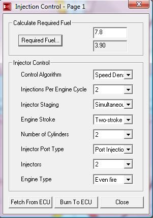
So, as I have the pertinant settings thus far:
Engine Constants:
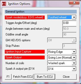
Tach Input/Ignition Settings:
Trigger Wheel Settings:
Does this look correct/my logic seem right? Is this how MS2e calculates when to fire the spark (i dont see any other combo of variables that would do it)? Thanks again!
BTW Ken, congrats on the marriage! when does it happen?
EDIT: one more thing... does the 2nd VR pulse have to go low before the first tooth goes high? It doesnt seem that way, but from what I read about the newest bit of filtering thats being written for it, it looks for both the rising and falling edges of the 2nd VR pulse?
Anywho, I've been thinking that the trigger wheel teeth number should be 12 for cam wheel (6 for crank wheel), even though this seemed to be giving me double the RPM than the engine should have been cranking at in megatune (although somehow the trailing-spark based tach was still correct)
This is because only 12 Ne teeth pass between each G tooth, which would explain my sync error that always manifests itself, regardless of what i'm doing with the 2nd trigger. Physically, this also makes sense, since 12 teeth pass the sensor over the course of one full 4-stroke cycle of rotor 1. However, since the full 4 strokes are happening over just one eccentric shaft rotation instead of two crank rotations, and we're getting two combustion events over those 360*, we need to set the engine as a two-stroke, 2 cyl engine under "engine constants".
Following that, since the number of cyls is set to 2, the engine type is even-fire, and the tooth #1 angle is 60* (360*/12 teeth, X 2 teeth since tooth #3 is at TDC), then it should follow that the MS will know that 60* after tooth #1 (so tooth #3) will be TDC firing for rotor 1, then TDC firing for rotor 2 would be at an even spacing of 180* + 60* = 240* (aka tooth #9). This would match up to the old 1-3-7-9 tooth counting of MS1e.
So, as I have the pertinant settings thus far:
Engine Constants:
Tach Input/Ignition Settings:
Trigger Wheel Settings:
Does this look correct/my logic seem right? Is this how MS2e calculates when to fire the spark (i dont see any other combo of variables that would do it)? Thanks again!
BTW Ken, congrats on the marriage! when does it happen?
EDIT: one more thing... does the 2nd VR pulse have to go low before the first tooth goes high? It doesnt seem that way, but from what I read about the newest bit of filtering thats being written for it, it looks for both the rising and falling edges of the 2nd VR pulse?
Last edited by toplessFC3Sman; 11-09-08 at 12:18 AM.
11-09-08, 03:03 PM
#24
MegaSquirt Mod
No, you should set it to 4 cylinders.
If you have the CAS stabbed as stock, tooth #1 angle should be 5, You should use 24-tooth cam wheel, with second trigger active on rising and every rotation of the crank.
Also, none of the released 2.1 betas have the noise filter yet. The noise filter measures the width of the 2nd trig pulse, and if the width is lower than the value you set, it tosses it out. You have to be careful not to set it too high, as that'll cause you to lose sync at high rpm.
I'm using the same lm1815 circuit I used with 1.0.2, and with ms1. (The one in the FAQ).
Oh, and I got married about 2 weeks ago, and thanks for the congrats!
Ken
11-09-08, 05:31 PM
#25
Hmmm.
It seems to be working with the settings I posted up as well, at least in terms of what i'm seeing with the o-scope. RPM is matching up, spark is happening at the right time (I'm using the 1-3-7-9 timing from MS2, which had involved stabbing the CAS differently IIRC so that tooth 3 lined up with TDC). The only difference from the settings I posted above is that I changed the "Wheel speed" and "every rotation of..." to Crank, and verified and changed the "ignition input capture" to falling edge. I have a feeling that the 2-cyl, 2-stroke with my settings works out to be the same as yours, just a different way of doing it.
With the LM circuit I've been using for MS1, it will keep falling out of sync even if i'm just bench-testing it (using a drill to spin a spare CAS), so I decided to play with the 2nd trigger circuit a bit. Eventually I found something that seemed to work perfectly (up to the 2000 RPM max my drill can go anyway)
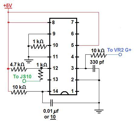
The big difference is the change to the RC circuit controlling the one-shot time at pin 14. The smaller you make the resistor and capacitor here, the shorter the one-shot high-true pulse is. I had noticed that as I made these bigger, sync would begin to break up at a lower RPM, even if the falling edge of this pulse didnt come close to the falling edge of the first tooth on the main wheel (triggered off of falling edge). I've only verified that perfect sync was maintained with the 0.01 microfarad cap up to 2000 RPM since thats where my drill topped out, but I think you may need to go lower to get up to 8k RPM. Currently I have a resistor that I think is 10 pF (the only markings on it are an underlined "10", but its effect on the RC circuit seems to imply that its 10 pF), and it was triggering the MS2 on the bench with no problems. A slightly wider pulse may be necessary once its in the car to separate it from possible noise, but I have yet to try that.
Other differences are as follows:
-The 5V to pin 5 sets the minimum positive arming voltage to a fixed 200 mV, which hopefully will help with input noise on the G+ line
-The lack of an RC circuit on pin 7 b/c if pin 5 is connected to 5v, this isnt doing anything anyway.
-Changing the resistor inline with the VR sensor from 18k to 10k, since i noticed at low RPMs (approx 200) that the signal at pin 3 was perilously close to the 200 mV cap imposed by 5V at pin 5
-The 1k resistor at pin 10 I'm almost positive is not necessary and was just left over from when I was trying other stuff (it serves no purpose now and is on an output pin), but since I moved the MS back into the car since I needed to drive somewhere and can't just plug it in to check, i decided to show it in the drawing.
I think thats all for now, I have some stuff I need to study for, so this will be on hold for a few days.
It seems to be working with the settings I posted up as well, at least in terms of what i'm seeing with the o-scope. RPM is matching up, spark is happening at the right time (I'm using the 1-3-7-9 timing from MS2, which had involved stabbing the CAS differently IIRC so that tooth 3 lined up with TDC). The only difference from the settings I posted above is that I changed the "Wheel speed" and "every rotation of..." to Crank, and verified and changed the "ignition input capture" to falling edge. I have a feeling that the 2-cyl, 2-stroke with my settings works out to be the same as yours, just a different way of doing it.
With the LM circuit I've been using for MS1, it will keep falling out of sync even if i'm just bench-testing it (using a drill to spin a spare CAS), so I decided to play with the 2nd trigger circuit a bit. Eventually I found something that seemed to work perfectly (up to the 2000 RPM max my drill can go anyway)
The big difference is the change to the RC circuit controlling the one-shot time at pin 14. The smaller you make the resistor and capacitor here, the shorter the one-shot high-true pulse is. I had noticed that as I made these bigger, sync would begin to break up at a lower RPM, even if the falling edge of this pulse didnt come close to the falling edge of the first tooth on the main wheel (triggered off of falling edge). I've only verified that perfect sync was maintained with the 0.01 microfarad cap up to 2000 RPM since thats where my drill topped out, but I think you may need to go lower to get up to 8k RPM. Currently I have a resistor that I think is 10 pF (the only markings on it are an underlined "10", but its effect on the RC circuit seems to imply that its 10 pF), and it was triggering the MS2 on the bench with no problems. A slightly wider pulse may be necessary once its in the car to separate it from possible noise, but I have yet to try that.
Other differences are as follows:
-The 5V to pin 5 sets the minimum positive arming voltage to a fixed 200 mV, which hopefully will help with input noise on the G+ line
-The lack of an RC circuit on pin 7 b/c if pin 5 is connected to 5v, this isnt doing anything anyway.
-Changing the resistor inline with the VR sensor from 18k to 10k, since i noticed at low RPMs (approx 200) that the signal at pin 3 was perilously close to the 200 mV cap imposed by 5V at pin 5
-The 1k resistor at pin 10 I'm almost positive is not necessary and was just left over from when I was trying other stuff (it serves no purpose now and is on an output pin), but since I moved the MS back into the car since I needed to drive somewhere and can't just plug it in to check, i decided to show it in the drawing.
I think thats all for now, I have some stuff I need to study for, so this will be on hold for a few days.