
Megasquirt MS Install Within Stock ECU Case

Thread Starter
RX-7 Alumni
Joined: Oct 2002
Posts: 1,140
Likes: 1
From: Spacecenter Houston
MS Install Within Stock ECU Case
Here's a repost from the MSEFI. Since it's totally RX-7, I thought I'd add it over here too.
Have any of you guys installed the MS (v3.0 preferably) within a stock ECU case?
I have a Nippondenso ECU case sitting here in front of me and it's 6.3" across by 6.7" vertical and about 1.4" thick. The MS heatsink is 6" across so it looks like it will fit OK. Not only will this make the MS install a drop in--literally, but I should be able to set it up to where I can use the stock wiring connectors in the ECU and not have to make any changes to the wiring harness. If I mount it horizontally on the 6.3" dimension I can have the DB37 sticking out on one side and still use the stimulator for checkout (without the car wiring on of course).
Do you think there will be any electrical or install problems running two connectors onto the DB37 location on the PCB? Most likely I'd run some kind of jumper wires internally from the stock connectors to the DB37 pins.
If this works an added bonus is I could easily build a break out box that connects to the DB37 and would allow in car checkout of voltages being received by MS.
Only other issue I could think of is making sure the heat sink strip is well mounted to the internal frame of the stock ECU.
Please let me know if you guys have any suggestions.
TIA,
Scott
MegaSquirt Mod
Joined: Sep 2004
Posts: 4,721
Likes: 1
From: Maryland
tofuball and I have a stock ECU with connectors waiting for exactly that.
We're going to put his megasquirt, dual lm1815 circuit, extra circuit that actuates his VDI and aux ports, and anything else we can think of inside the stock ecu case. We just haven't had time to do it, and his other car is broken so we can't do anything major to the megasquirt until his other car is drivable again.
So yes, it should be possible.
We're going to do this on the 2.2 board though.
The V3 board's heatsink strip is meant to mount on the v3 board itself. There's a big bare ground area that the heatsink sits on, and then you put the heatsinked components on that... so you could just mount the whole board heatsink and all in the cpu case.
Last edited by muythaibxr; Aug 20, 2005 at 05:21 PM.
Thread Starter
RX-7 Alumni
Joined: Oct 2002
Posts: 1,140
Likes: 1
From: Spacecenter Houston
Originally Posted by muythaibxr
So yes, it should be possible.
I'm gonna go ahead and get some bad ECU's.
Thanks,
Scott


Joined: Dec 1999
Posts: 7,855
Likes: 517
From: Behind a workbench, repairing FC Electronics.
I wonder what else you can cram into the ECU case... Perhaps an alarm system. Use the starter kill relay to instead of feed/cut power to the starter solenoid, cut power to the +12v to the MS. And perhaps a small 12volt battery as backup.
Registered Abuser
Joined: Jul 2003
Posts: 697
Likes: 0
From: Upper Marlboro
Originally Posted by muythaibxr
tofuball and I have a stock ECU with connectors waiting for exactly that.
We're going to put his megasquirt, dual lm1815 circuit, extra circuit that actuates his VDI and aux ports, and anything else we can think of inside the stock ecu case. We just haven't had time to do it, and his other car is broken so we can't do anything major to the megasquirt until his other car is drivable again.
So yes, it should be possible.
We're going to do this on the 2.2 board though.
The V3 board's heatsink strip is meant to mount on the v3 board itself. There's a big bare ground area that the heatsink sits on, and then you put the heatsinked components on that... so you could just mount the whole board heatsink and all in the cpu case.
We're going to put his megasquirt, dual lm1815 circuit, extra circuit that actuates his VDI and aux ports, and anything else we can think of inside the stock ecu case. We just haven't had time to do it, and his other car is broken so we can't do anything major to the megasquirt until his other car is drivable again.
So yes, it should be possible.
We're going to do this on the 2.2 board though.
The V3 board's heatsink strip is meant to mount on the v3 board itself. There's a big bare ground area that the heatsink sits on, and then you put the heatsinked components on that... so you could just mount the whole board heatsink and all in the cpu case.
MegaSquirt Mod
Joined: Sep 2004
Posts: 4,721
Likes: 1
From: Maryland
Originally Posted by 13Beast REW
A little upset that I'm just now noticing this thread but after all that work I did removing the stock ecu female connector you guys still haven't put it to use yet? What's goin on with Jason's car. I haven't exactly been keeping up with the MD thread lately either. I'm also planning on doing this with my US spec ecu box. But then again... my wiring is already a little hacked up because of the japanese engine harness interfacing with the US Spec front harness so it might defeat the whole purpose of the stock box.
We're going to use that stock ecu connector soon now though, I ordered jason's new wires for his harness, and soldering it together and all that will commence as soon as the wires arrive; so all that work you put in helping us won't go to waste.
So yeah, jason's 'vert has only been drivable again for like 2 weeks or something, so we're just now getting back to actively working on it, that's why we haven't use the stock connector yet.
Ken
Thread Starter
RX-7 Alumni
Joined: Oct 2002
Posts: 1,140
Likes: 1
From: Spacecenter Houston
Adapting Stock Wiring?
Ken, I was curious how you plan to adapt the stock wiring to the MS?
I was thinking about using a vertical mount db37 inlieu of the right angle mount supplied in the kit. Then bring some wires from the stock ECU connectors to a mating db37 into the vertical mount. Not even sure there is enough room for this.
Of course the best way is just solder the stock ECU connectors straight onto the MS board with wires, but then you have no way to use the stim. I guess if someone came up with a source for the harness side connectors, we could adapt the stim db37 output to the harness side connectors. Then just plug and play with the stim straight into the stock ECU connectors. This option could totally eliminate the db37 from the MS and provide the best connection possible.
Any of you guys have a good source for stock ECU connectors WITH crimp on pins?
Trending Topics
Thread Starter
RX-7 Alumni
Joined: Oct 2002
Posts: 1,140
Likes: 1
From: Spacecenter Houston
Back to work!
After "Running from Rita" I recently started work on the MS install in the stock ECU.
Spent about 2 hours using a angle grinder and dremel to fit the board and heat sink.
Here's a pic of the board fit-up along with a prototype board for a three hole IC pattern.
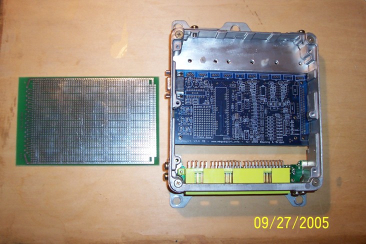
Looks like it will all go in with no problem, just won't be able to use the DB37 connector. Oh well, I'll have to build up a stim pigtail and connect each wire individually to use the stim.
Notice I built up a larger heat sink to fit within the case, on the opposite side of the heat sink I have countersunk screws that hold the heat sink securely to the case. The screws thread into the standard board mount holes on the stock ECU. The DB9 fit very well also.
The prototype board was a good find at $4, with a very small amount of trimming I will easily fit the board on the "top rack". Error's board would be great but it is small and has much more than I needed. I plan on populating the prototype board with the following circuits: single LM1815 for CAS, EGT, 2 output circuits (1 custom with on/off), boost control. There will be plenty of room for anything else I want to add.
I move pretty slow on this stuff, hope to be logging in November and running fuel in December.
More to come,
Scott
Spent about 2 hours using a angle grinder and dremel to fit the board and heat sink.
Here's a pic of the board fit-up along with a prototype board for a three hole IC pattern.
Looks like it will all go in with no problem, just won't be able to use the DB37 connector. Oh well, I'll have to build up a stim pigtail and connect each wire individually to use the stim.
Notice I built up a larger heat sink to fit within the case, on the opposite side of the heat sink I have countersunk screws that hold the heat sink securely to the case. The screws thread into the standard board mount holes on the stock ECU. The DB9 fit very well also.
The prototype board was a good find at $4, with a very small amount of trimming I will easily fit the board on the "top rack". Error's board would be great but it is small and has much more than I needed. I plan on populating the prototype board with the following circuits: single LM1815 for CAS, EGT, 2 output circuits (1 custom with on/off), boost control. There will be plenty of room for anything else I want to add.
I move pretty slow on this stuff, hope to be logging in November and running fuel in December.
More to come,
Scott
Last edited by Rex4Life; Sep 28, 2005 at 03:04 PM.
MegaSquirt Mod
Joined: Sep 2004
Posts: 4,721
Likes: 1
From: Maryland
Cool, looks like you're doing a pretty clean install so far. When I get home, I'll post a pic of what we have so far for tofuball's stock ECU case install.. We're going to be stuffing one of error*'s msns-extra boards in, as well as a techedge wideband O2 controller.
When I get home, I'll post a pic of what we have so far for tofuball's stock ECU case install.. We're going to be stuffing one of error*'s msns-extra boards in, as well as a techedge wideband O2 controller.
Burning up Time
Joined: Sep 2004
Posts: 805
Likes: 2
From: Earth
Originally Posted by muythaibxr
Cool, looks like you're doing a pretty clean install so far. When I get home, I'll post a pic of what we have so far for tofuball's stock ECU case install.. We're going to be stuffing one of error*'s msns-extra boards in, as well as a techedge wideband O2 controller.
When I get home, I'll post a pic of what we have so far for tofuball's stock ECU case install.. We're going to be stuffing one of error*'s msns-extra boards in, as well as a techedge wideband O2 controller.MegaSquirt Mod
Joined: Sep 2004
Posts: 4,721
Likes: 1
From: Maryland
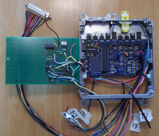
It's nowhere near finished yet, and we took off our daughterboard and other stuff to do the remount to the stock ECU case, but here it is:

I'll take more pics as we get further along. The board on the right is our dismantled and ready to rewire techedge wideband O2 (2a0) unit which will also go in the stock case.
Oh yeah, and tofuball has been doing the grinding and drilling to get all this stuff to fit in the stock case.
I'll take more pics as we get further along. The board on the right is our dismantled and ready to rewire techedge wideband O2 (2a0) unit which will also go in the stock case.
Oh yeah, and tofuball has been doing the grinding and drilling to get all this stuff to fit in the stock case.
Last edited by muythaibxr; Sep 29, 2005 at 07:44 AM.
Thread Starter
RX-7 Alumni
Joined: Oct 2002
Posts: 1,140
Likes: 1
From: Spacecenter Houston
Update!
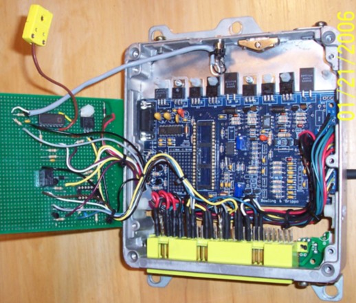
OK, here's an updated pic of my MS installed in the stock ECU. Still have the db37 wires connected and a few other pigtails not connected. Later when I go full MS I'll cut the pigtails and connect the wires to the stock connector. So the wiring is setup for temporary use.
Notice EGT and WBO2 connectors at the top of the ECU.
The project board has the following circuits: EGT temp, CAS input conditioner, EBC controller, and two output circuits--one with a dual on/off output via the relay. Only used 2/5 of the board, much more room available. The IC layout of the board was really nice to work with. I used sockets for both chips, this made it easy to make connections between pins underneath the socket--really cleaned up the install.
Last night I was able to test the EGT and output circuits to veryif proper operation. Not too bad for my first try.
Should be datalogging stock ECU this week and hopefully running MS fuel next weekend.
Scott
p.s. Almost forgot, the extra resistors used on each LED for rotary spark output are difficult to install on the v3 board--basically it's a tite fit--but requires some skill and patience. Also, I was able to get the LEDs installed such that they fit into the side of the ECU case. Not really required but nice.
Last edited by Rex4Life; Oct 30, 2005 at 01:52 PM.
Senior Member
Joined: Sep 2002
Posts: 286
Likes: 0
From: Wandering the USA in my Winnebago
I'm pretty much finished with my V3 board in the stock case. One of my big constraints is to keep everything contained inside the case. I mounted connectors vertically to help with that. Vertical mounting of the heat sink seemed to work better, too. I added a couple extra connectors for occasional attachment of a wideband O2 sensor and easy switching between the standard MS MAP sensor (mounted on the top side of the board) and the stock S4 boost sensor on the harness. This setup should be plug and play with a totally stock system. Fire it up this weekend.
MegaSquirt Mod
Joined: Sep 2004
Posts: 4,721
Likes: 1
From: Maryland
that's cool, tofuball and I actually wired all of his stuff directly to the stock connector using wires from the vias that the plugs normally plug into... we also stuffed an msns-extra daughtercard and his techedge wideband in the same case.... it looks pretty messy inside, but looks very clean on the outside. We even used pins on the stock connector for his serial port connection.
Senior Member
Joined: Sep 2002
Posts: 286
Likes: 0
From: Wandering the USA in my Winnebago
All of that makes good sense for a typical application. My motivation for most of my choices is that my racing rules that don't allow any disturbance to the stock wiring harness, nor any connection to the ECU other than the stock harness.
Edit: I used the 37 pin connector so I could still easily connect the stim.
Edit: I used the 37 pin connector so I could still easily connect the stim.
Senior Member
Joined: Sep 2002
Posts: 286
Likes: 0
From: Wandering the USA in my Winnebago
Originally Posted by muythaibxr
ahh, I see... but the rules allow for a full standalone ECU? 
Thread Starter
RX-7 Alumni
Joined: Oct 2002
Posts: 1,140
Likes: 1
From: Spacecenter Houston
Upgrading my Megatune and firmware.
So far I've only done the Megatune upgrade, I went from version b514 to b717. No big problems so far, think I have it to where I could run either version. The b717 version looks pretty nice. My latest msq file imported directly with 4 warnings: INVALID types for HCutLCType, HCutType, OvrBCutType, pwmidlewhen. All I had to do was go into the General menus for Hard Cut/Limiter Type, and Idle Control and select some valid values, then save those settings as a new msq file.
Next I need to upgrade firmware. First I'd like to find out how to upload my current firmware and save it off--just in case. Then I'll download the 026i firmware from Ken, install it, and redo the resistor bias stuff using Roger's Easytherm.
Keeping fingers crossed,
Scott
Next I need to upgrade firmware. First I'd like to find out how to upload my current firmware and save it off--just in case. Then I'll download the 026i firmware from Ken, install it, and redo the resistor bias stuff using Roger's Easytherm.
Keeping fingers crossed,
Scott
Thread Starter
RX-7 Alumni
Joined: Oct 2002
Posts: 1,140
Likes: 1
From: Spacecenter Houston
Build complete!
Well I'm finally finished with the MS install into the stock ECU case--mostly plug and play with the stock S4 T2 harness.
There were two wires that needed changing on the stock harness:
1) The fuel pump circuit opening relay was added to the ECU connector on an unused pin--normally the ECU doesn't control relay--so in the stock configuration there is no wire running into the ECU for relay control.
2) I'm running an MS EBC wire back to the engine bay thru one of the stock pressure sensor wires.
Some bonus features that I added:
-- EGT sensor input
-- Second O2 sensor input
-- Electronic boost control circuit
-- two relay output circuits
-- BAC control mods
-- And of course the second lm1815 CAS sensing circuit for FC ignition
The overall quality and result came out very good:
Can't see it, but the unit has the three led's on the left side and the db-9 comm interface.
Really sweet.
Last edited by Rex4Life; Jan 29, 2006 at 07:20 PM.
Back.
Joined: Apr 2004
Posts: 890
Likes: 0
From: San Diego
Looks great.. keep us updated on your overall progress!
And if it all works, maybe a write-up that details what you did exactly, as far as the circuit building, that differs from the build instructions on the megasquirt.info? I know I'd appreciate it!
And if it all works, maybe a write-up that details what you did exactly, as far as the circuit building, that differs from the build instructions on the megasquirt.info? I know I'd appreciate it!

Thread
Thread Starter
Forum
Replies
Last Post
trickster
2nd Generation Specific (1986-1992)
25
Jul 1, 2023 04:40 PM
immanuel__7
2nd Generation Specific (1986-1992)
89
Sep 5, 2015 10:23 AM