
Megasquirt Missing teeth CAS setup and easytherm.

Thread Starter
Rotary Enthusiast
Joined: Aug 2002
Posts: 850
Likes: 0
From: MO
Missing teeth CAS setup and easytherm.
in the official faq i didnt see much info about the missing teeth setup and no info on howto setup easytherm.
do we have to use easytherm even if we replace the resistor with a 47k? if so can we get some info on what to do with it? just open it and set it to rx7 and hit "download to megasquirt"?
also, to confirm...
this is how we cut the teeth (or any 2 teeth across from each other)
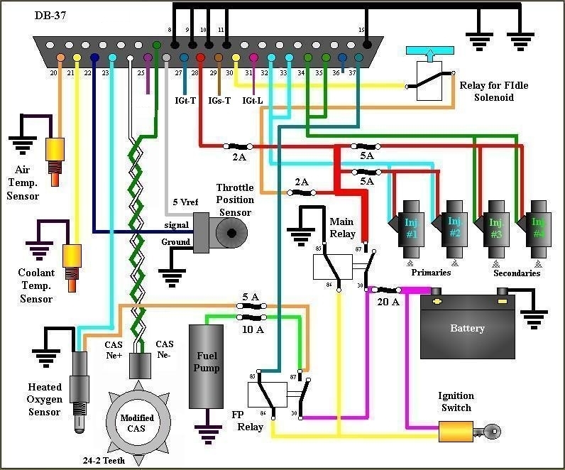
this is the wiring for it
and can we get some screen shots on howto set it up in megatune?
...and also howto stab it correctly. maybe a pic of how it should be lined up when stabbed.
thanks
do we have to use easytherm even if we replace the resistor with a 47k? if so can we get some info on what to do with it? just open it and set it to rx7 and hit "download to megasquirt"?
also, to confirm...
this is how we cut the teeth (or any 2 teeth across from each other)
this is the wiring for it
and can we get some screen shots on howto set it up in megatune?
...and also howto stab it correctly. maybe a pic of how it should be lined up when stabbed.
thanks
to stab it, one way would be to look in the recent "stabbing the CAS" thread, stab the cas as described there, but your wheel decoder settings would be different. They would be:
Trig A: 9
Ret A: 11
Trig B: 3
Ret B: 5
Trigger angle is 60, cranking angle is 0 etc.
I prefer the 2nd VR sensor, cause even if missing tooth is working properly, 2nd VR will still have less noise, you just need to build a second circuit
Trig A: 9
Ret A: 11
Trig B: 3
Ret B: 5
Trigger angle is 60, cranking angle is 0 etc.
I prefer the 2nd VR sensor, cause even if missing tooth is working properly, 2nd VR will still have less noise, you just need to build a second circuit
Thread Starter
Rotary Enthusiast
Joined: Aug 2002
Posts: 850
Likes: 0
From: MO
im assuming this is right....
(from the faq but not labeled)

i also found this...
thanks jobro. very good explanation.
(from the faq but not labeled)
i also found this...
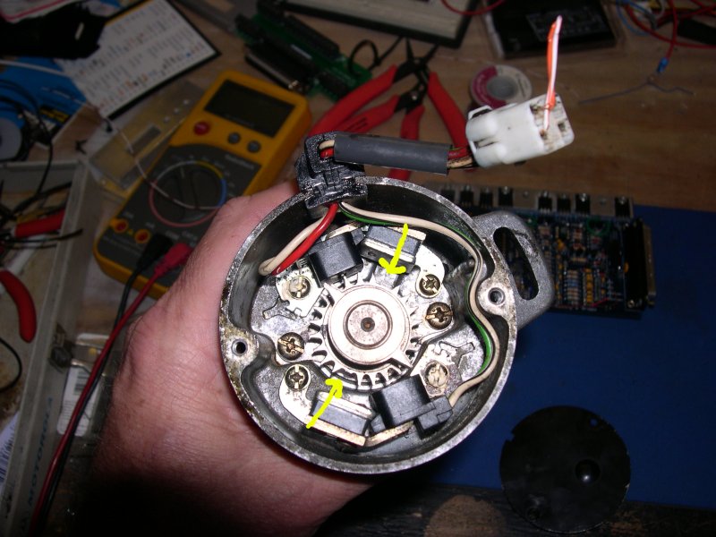
For cutting opposing teeth, this is what I did.
Pull cover off the CAS.
Turn engine to 5ATDC (-5BTDC), ie where the First timing mark is on a factory pulley.
Allign CAS in centre of adjustment, then rotate it slightly counterclockwise, push CAS into engine without holding the wheel steady.
Pay particular attention to how pushing the CAS into the drive teeth, turns CAS, it will turn 2 more teeth, and end up in dead centre of adjustment again. This is exactly what you want. The tooth, current on or closest to the Ne sensor is the 5ATDC tooth now, if you do this.
Count back one tooth(in counter clockwise direction), if that tooth was -5ATDC, now you are on 25BTDC, count back another, now you are on 55BTDC, count back one more tooth. This is the tooth to cut.
Mark to tooth to chop with black Nikko pen (permanent marker, bearing blue, nail polish/ whiteout you guys might call that liquid paper). Remove that tooth, and the one completely opposite to it.
You will need to strip down the CAS to remove the 2 teeth.
Get a punch/nail and hammer on the pin holding the gear on the bottom of the CAS off. Remove the 4 screws holding the sensors inside the CAS body. remove the sensors and be very gentle with them. Take the one that was for the 2 tooth wheel and store it in a safe place (good working backup incase you fudge up the other one).
Remove the other 2 screws holding the shaft/bearing assembly in, push shaft out, then remove the teeth. Reassemble in reverse. leaving out 2 tooth vr sensor.
I'll explain the trigger settings for you.
Because the missing tooth is on the 85BTDC, the tooth count is reset here. The next tooth passes the sensor, and the MS adds 1 to the reset tooth count.
you can see you are on 55BTDC when this happens. The trigger settings are usually 1 3 7 9 for missing tooth setup on 12-1 wheel.
So the ignition timing starts, and the ECU just does a delay to retard the timing back to where you want it.
As the engine keeps turning the 2nd tooth passes the Ne VR sensor, count=2.
Turns more, 3rd tooth passes the VR sensor. count=3.
Because you setup the timing to use crank based timing, tooth 3 passing the VR sensor tells the ECU to fire here for cranking timing, you see this will result in a cranking spark advance of -5BTDC or 5ATDC.
As soon as the engine rpm gets above the cranking rpm value the timing changes over to using the 1st tooth trigger and the appropriate delays.
The teeth 7 and 9 are just the same as teeth 1 and 3 only 6 teeth away, ie 6x30degrees = 180degrees out of phase. Which is exactly how much the front and rear rotors are!
Hopefully that makes a bit more sense for you!
thanks jobro. very good explanation.
Thread Starter
Rotary Enthusiast
Joined: Aug 2002
Posts: 850
Likes: 0
From: MO
i dont know if its like this on purpose or not but in the picture with the removed teeth the cut teeth are 3 away clockwise from where the sensor is pointing. jobros explanation says counter-clockwise. maybe the picture isnt aligned any certain way.. just wanna confirm. eh?
Full Member
Joined: Aug 2005
Posts: 179
Likes: 0
From: LA, CA
the vr sensor should lineup with the 3rd tooth after the missing tooth, counter-clockwise.
more on that in this thread: https://www.rx7club.com/megasquirt-forum-153/stabbing-cas-stuff-660410/
more on that in this thread: https://www.rx7club.com/megasquirt-forum-153/stabbing-cas-stuff-660410/
yea, to use the settings shown in that wheel decoder settings image you linked, you would need to line the CAS up on the 3rd tooth on the bottom wheel to pass the sensor after the missing tooth (just like my 3rd ms-paint illustration of the CAS in the other thread has the 3rd tooth on the bottom wheel after one of the teeth on the top wheel lined up). This means that you will have to turn the CAS 7 teeth clockwise from the 3rd CAS picture in the other thread, and then stab it, to be able to use the 1,3,7,9 settings.
If you wanted to replicate the 3rd picture in the other thread exactly when you installed it, your settings would NOT be the ones i posted the first time (oops, i mis-counted), they would be these:
Trig A: 8
Ret A: 10
Trig B: 2
Ret B: 4
If you wanted to replicate the 3rd picture in the other thread exactly when you installed it, your settings would NOT be the ones i posted the first time (oops, i mis-counted), they would be these:
Trig A: 8
Ret A: 10
Trig B: 2
Ret B: 4
Trending Topics
 thats what i was picturing but that will help for anyone in the future for sure. hopefully noise wont be too bad.
Thread Starter
Rotary Enthusiast
Joined: Aug 2002
Posts: 850
Likes: 0
From: MO
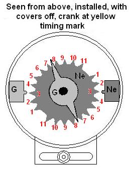
this is how the cas would relate to the above picture though (i know tooth 1 wouldnt necessarily be 0 degrees, just relating to picture)...
tooth 1 - 0 degrees
tooth 2 - 30 degrees
tooth 3 - 60 degrees
tooth 4 - 90 degrees
tooth 5 - 120 degrees
tooth 6 - 150 degrees
tooth 7 - 180 degrees
tooth 8 - 210 degrees
tooth 9 - 240 degrees
tooth 10 - 270 degrees
tooth 11 - 300 degrees
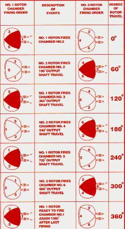
in the picture the spark plugs fire at 120 also. why not on tooth 5 and 11???
tooth 1 - 0 degrees
tooth 2 - 30 degrees
tooth 3 - 60 degrees
tooth 4 - 90 degrees
tooth 5 - 120 degrees
tooth 6 - 150 degrees
tooth 7 - 180 degrees
tooth 8 - 210 degrees
tooth 9 - 240 degrees
tooth 10 - 270 degrees
tooth 11 - 300 degrees
in the picture the spark plugs fire at 120 also. why not on tooth 5 and 11???
and its not 30 degrees on the rotor, its 30 degrees on the eccentric shaft (altho I may slip sometimes and say crank, cause just about all of the generic documentation on MS is for piston engines). Each rotor spins at 1/3 of the speed of the e-shaft, but since all 3 faces fire, one face on each rotor fires once per e-shaft revolution.
look in that diagram... at 360* of rotor travel, its 1080* of eshaft travel.
look in that diagram... at 360* of rotor travel, its 1080* of eshaft travel.
well, thats the teeth spacing, but the CAS spins at half the speed of the e-shaft, so for one e-shaft revolution, the CAS goes half-way around. The events described in the picture are at TDC, which for this setup is occuring at teeth 3 and 9 each time. So to go down labelling the pictures, its 3,9,3,9,3,9,3... The bolded numbers are for the 2nd half of the CAS wheel
you need to swap to the 47k resistor, and do easytherm and burn it to the MS. easytherm already has RX-7 settings in it so at least you dont need to go make an ice-bath and boil a pot of water with your multimeter ready.

Thread
Thread Starter
Forum
Replies
Last Post
Jeff20B
1st Generation Specific (1979-1985)
73
Sep 16, 2018 07:16 PM