
Megasquirt Boost control solenoid wiring

Boost control solenoid wiring
I�m looking for advice on connecting a boost control solenoid to my MS3X using the �boost� wire (PP3). I see 3 possible ways to wire this, and I�m not sure which is correct:
a) 12V to one BCS wire, MS3X boost wire to the other BCS wire.
b) Same as a), but with a diode between the two wires to control kickback (just like the BAC wiring).
c) Use a MOSFET transistor with a couple of resistors and a diode (pre-MS3 guys were using this setup), as shown here:
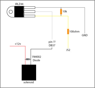
DIYautotune's boost control solenoid description says: "One wire connects to a 12 volt source, the other to the Megasquirt, the valve wiring is not polarized so it does not matter which wire you run to 12v+ and which to switched ground at the EMS."
This seems to suggest option a, but I would like to get confirmation before I move forward.
Thanks.
a) 12V to one BCS wire, MS3X boost wire to the other BCS wire.
b) Same as a), but with a diode between the two wires to control kickback (just like the BAC wiring).
c) Use a MOSFET transistor with a couple of resistors and a diode (pre-MS3 guys were using this setup), as shown here:
DIYautotune's boost control solenoid description says: "One wire connects to a 12 volt source, the other to the Megasquirt, the valve wiring is not polarized so it does not matter which wire you run to 12v+ and which to switched ground at the EMS."
This seems to suggest option a, but I would like to get confirmation before I move forward.
Thanks.


Thread
Thread Starter
Forum
Replies
Last Post
Skeese
Adaptronic Engine Mgmt - AUS
65
Mar 28, 2017 03:30 PM
stickmantijuana
MoTeC
5
Sep 10, 2015 07:58 PM