
Haltech haltech e6x wiring Q's (with pics)

first off it is a haltech e6x with i think it is the flying lead harness. i have a couple of wires that im not to sure were they need to go.i have looked at hitman's site and a couple other but im still sorta confused.
they are as follows:
these 3 bundles, obviously it says what they are for but im not sure were they go. pwm, road speed and idle control.

next is the ign trigger leading and trailing and aux. out

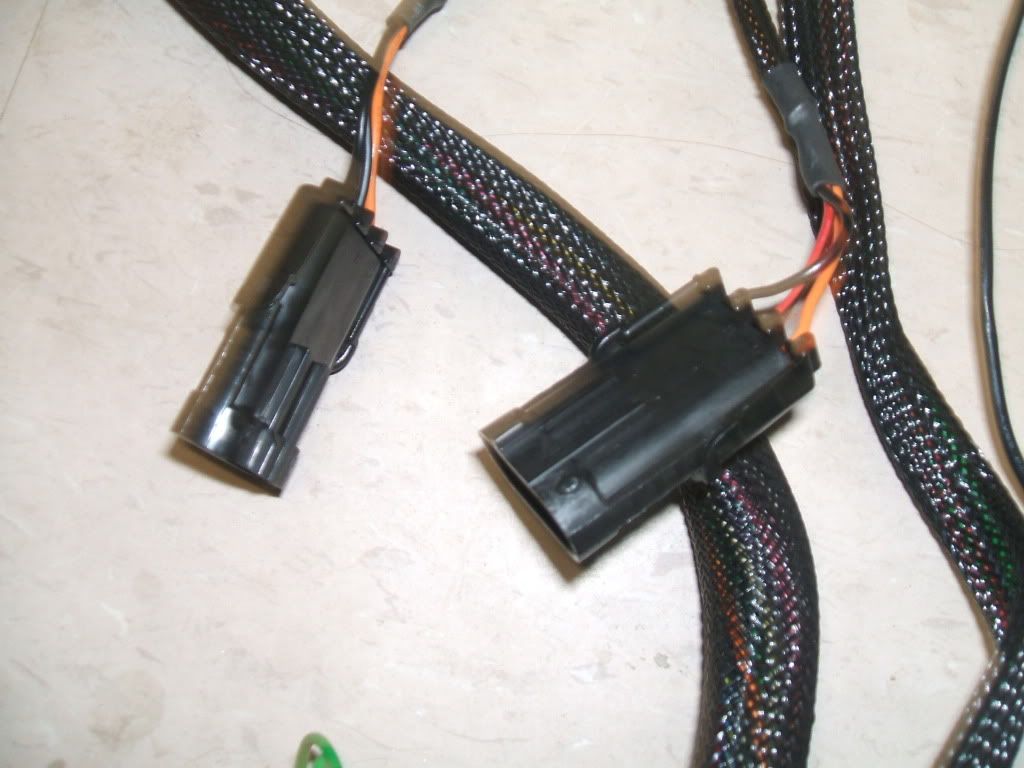
and lastly these 2 plugs
any help would be great, this is my first haltech installation and i just want to try to do it right.
they are as follows:
these 3 bundles, obviously it says what they are for but im not sure were they go. pwm, road speed and idle control.
next is the ign trigger leading and trailing and aux. out
and lastly these 2 plugs
any help would be great, this is my first haltech installation and i just want to try to do it right.
The first 3 bundles, "PWM", "Road Speed" and "IDLE" are:
PWM, auxiliary output wires to connect things like shift lights, fans, boost control solenoid, controlling a nitrous solenoid, 2 or 3 wire idle valves, etc.
Road Speed, the speed sensor input wires, 12V, signal and ground.
IDLE, these are for 4 wire idle valves exclusively, you dont need them since the FC's and FD's had 2 wire valves, one was 12V and the other signal (a PWM set to BAC).
The wires marked as trigger wires seem to bee spliced onto the main trigger wires since the colors and gauges dont match, strip them back till you get to the thick gray shielded wire with the 4 thing tirgger wires inside, yellow, red, green blue. Or, measure continuity to find out which are which.
Finally those 2 connectors, i am assuming they are the ones close to the main ECU connector with the same length as the serial connector wire are Spare A/D and Trim input.
I strongly recommend you read through your manual and also download and print the E6X wiring diagram, all this information is there.

Thread
Thread Starter
Forum
Replies
Last Post
Claudio RX-7
Haltech Forum
5
Apr 23, 2019 02:50 PM
stickmantijuana
MoTeC
5
Sep 10, 2015 07:58 PM
82streetracer
1st Generation Specific (1979-1985)
7
Aug 23, 2015 09:28 AM