When you click on links to various merchants on this site and make a purchase, this can result in this site earning a commission. Affiliate programs and affiliations include, but are not limited to, the eBay Partner Network.
13B IGN-1A Smart Coils Sub Harness Diagram/Feedback
Hello All,
I'm moving along in the harness build for my FD RX-7 that will be running a Haltech Elite 1500 ECU. I am building the ignition as a separate sub harness that will connect to main harness via 8 way DTM and separate 2 way DTP for power supply.
I will like to ask for you feedback on how I currently have it setup. I am particularly interested in the wire gauge I've selected for the Rotor Hsg grounds and the sensor grounds.
For sensor ground (Pin B on coils) to ECU I've used 20AWG coming from each coil joined into a single 18AWG that will go to ECU sensor ground pin. Is the 18AWG enough for the 4 coils? I have not found any information about current thru the sensor ground on the coils.
Similarly for the engine grounds (Pin C on coils) I have selected 20AWG coming from each coil. Front Rotor coils (L1 and T1) will be joined to a single 18AWG and grounded to front rotor (Rotor 1). Rear Rotor coils (L2 and T2) will be joined to a single 18AWG and grounded to rear rotor (Rotor 2). Again is the 18AWG enough for 2 coils together?
18awg should be enough but if you want you can group l1(c and d) on a 18awg and t1 c and d) on a 18awg and terminate both of them on one ring terminal to the rotor housing. As for the sensor ground I don�t see why 20awg shouldn�t be sufficient. It�s being mated to the haltech sensor ground which is a 20 or maybe 22awg wire. Also why have 2 separate connectors? Why not use a 12 pin DT connector and populate it with all your ign signals 4 12v wires for your coils and 4 signal grounds which can then be spliced into two or maybe 1 signal ground on the other side of the harness. Leaving it with just one connector for the sub harness.
18awg should be enough but if you want you can group l1(c and d) on a 18awg and t1 c and d) on a 18awg and terminate both of them on one ring terminal to the rotor housing. As for the sensor ground I don’t see why 20awg shouldn’t be sufficient. It’s being mated to the haltech sensor ground which is a 20 or maybe 22awg wire. Also why have 2 separate connectors? Why not use a 12 pin DT connector and populate it with all your ign signals 4 12v wires for your coils and 4 signal grounds which can then be spliced into two or maybe 1 signal ground on the other side of the harness. Leaving it with just one connector for the sub harness.
I thought about combining the L1 and T1 C and D grounds, but the instructions for the coils specifically state that this should be kept separate. This aligns with @C. Ludwig and @DC5Daniel latest discussion on this thread: https://www.rx7club.com/haltech-foru...-e11v2-991984/ . It appears that grounding C and D together can result in ignition breakup at higher RPM's as reported by @Kalle on the same thread.
I like the idea of using the 12 pin DT series connector instead of one DTM 8 and one DTP 2. I originally had it split into two separate connectors thinking I was going to use 10AWG or 12AWG for combined power supply to the 4 coils since my battery is in the rear. I guess that is another question, now I'm wondering if 14AWG is enough for power supply to the 4 coils?
it seems like no matter how many times it� said, warned about, posted, and printed that there�s always somebody not wanting to follow those IGN-1A grounding directions.
what�s enough and what�s proper aren�t always the same thing. The ignitor is rated at 19A maximum. In general it won�t ever likely see that amp rating, and certainly not sustained/continuously, but it should ar least be referenced and known.
Here�s the mS - V - A chart for them
from there, determining the general length and loading along with an appropriate safety factor should be a fairly straightforward process.
it seems like no matter how many times it’ said, warned about, posted, and printed that there’s always somebody not wanting to follow those IGN-1A grounding directions.
what’s enough and what’s proper aren’t always the same thing. The ignitor is rated at 19A maximum. In general it won’t ever likely see that amp rating, and certainly not sustained/continuously, but it should ar least be referenced and known.
Here’s the mS - V - A chart for them
from there, determining the general length and loading along with an appropriate safety factor should be a fairly straightforward process.
@TeamRX8 , thanks for that handy chart I have not seen that before. My AEM coils did not come with it.
Your comment on not following the grounding directions has me a little bit confused. My diagram above, from my understanding, is exactly how they are meant to be grounded based on AEM's diagram. Are you suggesting my diagram is incorrect? Would appreciate your help there.
It seems like 5ms dwell time would be plenty to get ~150mJ of energy at 8500 RPM. Base on your handy chart at 13.8V (14V from chart) should be right around 8-10 amps. I threw a 20% SF on that to get max current draw 12A which puts me at max continuous current for 14 AWG wire which is what my diagram shows.
Am I missing something here?
Thanks again for the feedback
EDIT: NVM I realized my diagram is using 18 AWG for each individual coil which would not be the appropriate size for a 5ms dwell time.16 AWG PER coil would be more appropriate per coil based on 5ms dwell time.
Last edited by Michael Garcia; Dec 12, 2020 at 04:41 PM.
sorry, that was just in response to the one post discussing the grounding, because if I had that argument once, then it’s been at least 2 dozen times more. It wasn’t intended at you, just me ranting on the point in general.
sorry, that was just in response to the one post discussing the grounding, because if I had that argument once, then it�s been at least 2 dozen times more. It wasn�t intended at you, just me ranting on the point in general.
Hahaha, fair enough! Thanks again for that nice chart!
I responded to your post over at HPA, you're more than welcome to go heavier gauge but you wont need to, depending on quality of wire and temperature its being rated at 18 AWG can carry 11-16 amps handily.
I responded to your post over at HPA, you're more than welcome to go heavier gauge but you wont need to, depending on quality of wire and temperature its being rated at 18 AWG can carry 11-16 amps handily.
Hey @dguy , yeah I also found another discussion where you and Andre provided some more feedback to someone else regarding power supply wire gauge to the coils. For direct fire, sounds like you have used 18 -20 AWG but for waste park you sometimes go down to 16 AWG.
This will be my first go at wiring so I appreciate all the feedback from others. I want to make sure I get it right the first time .
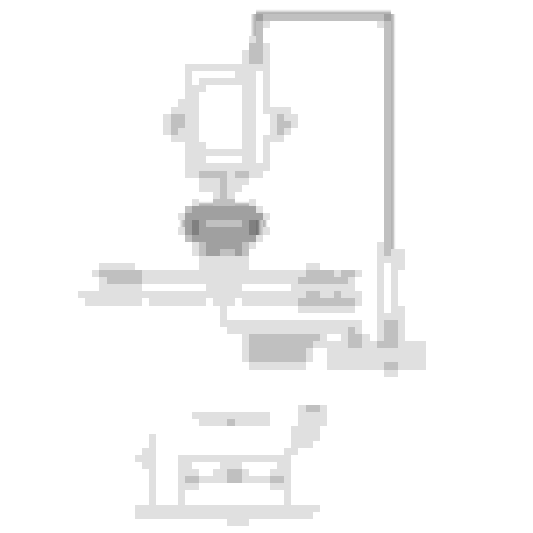
Here's the diagram of how I wired these coils up. I used 14ga. wire for the power and power ground up to the splice then 18ga to the coils. Used 20ga. for all the rest. Grounded the signal grounds to the ecu ground point on the back of the manifold, the power ground to the block, Spark ground to the rotor housing.
I followed the wire color scheme from the Haltech diagrams.
please tell me you didn't REALLY make all your signal wires white...
Exactly as it should be, with divorced grounds. Also I (and many other motorsports professionals) routinely use white as the only color for 'trigger/output/active' leads when building a complete harness. The only times that I dont is when a customer is getting some sort of flying lead harness or portion of a harness. Everything should be checked with a DMM.
Exactly as it should be, with divorced grounds. Also I (and many other motorsports professionals) routinely use white as the only color for 'trigger/output/active' leads when building a complete harness. The only times that I dont is when a customer is getting some sort of flying lead harness or portion of a harness. Everything should be checked with a DMM.
I'm a automotive technician, and chasing diagnostic problems with all the same color wires, sounds like a trip to the mad house.
I'm a automotive technician, and chasing diagnostic problems with all the same color wires, sounds like a trip to the mad house.
Fair, however diagnostics and repair of a consumer vehicle vs. a custom made vehicle/race car are completely different animals. If his diagram and what I've described stresses you out, best take some Xanax before you look at this:
That's aircraft wiring, but same/same. If anybody is curious or wants to waste a bit of time reading up and getting ideas for wiring moving forward this is helpful to give an overview of the whys and wheres: https://www.rbracing-rsr.com/wiring_ecu.html
In additional input to my previous response; the one Pin C ground is supposed to go to where the sparkplug is discharging for that coil. Which on a rotary engine means grounding to each rotor housing for the coils firing to it. However the diagram above shows them all coming together in a single grounding point rather than pairing them into two grounding points; one for each rotor pair to each housing. That might seem extreme, but as mentioned previously a number of people create issues for themselves thinking they’ll just group them all together, run to some other more convenient grounding point, etc.. Given the energy level these coils are capable of producing, it’s better to take heed on closely following the directions as clearly stated imo.
in the PFC group they recommend star connection to a common ground, I don't particularly agree. My ign-1a harness was built by C. Ludwig from LMS-EFI and it has a ground at each rotor housing and a batt neg ground.
Someone in the group tested and found there's continuity between pins B & D (43kOhm) and C isolated.
according to someone else,
"According to that reading (43k across B & D), it means that if an interfering signal as small as 47uA flows between pins B & D, the ignition coil will self trigger a spark without any ECU input. In this case, it would be very unwise to connect these 2 pins to different grounding locations as shown on the vendors instructions."
well here’s the nominal measurements that somebody else posted having received them from AEM for bench testing:
A to B = 10k Ohms A to C = 0k Ohms A to D = 36k Ohms A to E = 16k Ohms B to C = 0k Ohms B to D = 45k Ohms B to E = 26k Ohms C to D = 0k Ohms C to E = 0k Ohms D to E = 20k Ohms
I much prefer a simple HEI tester (looks like a sparkplug without a ground strap) to load test them and the wires rather than using that measurement method.
.
The reason I called the previous resistance values suspicious, are all the "0k Ohm" readings on pin C. With 0k to every pin, then all the pins would be shorted together. Clearly the person who posted that info does not understand how to read an ohmmeter.
My testing show all pins to C are actually OL, and not 0k Ohms.
There is a big, infinite actually, difference between a 0k Ohm reading and the "OL" that is displayed on a digital ohmmeter when there is no continuity/open circuit.
Below are the results of my test. Note that I tested each pin, then reversed the leads and tested again. I only posted those values that were different. The different values demonstrate the bias found in most semiconductors
resistance (Ohms)
+ -
A - B 9.97k
A - D 36.54k ______ D - A 22.85k
A - E 15.9k ______ E - A 15.54k
B - D 46.5k ______ D - B 34.2k
B - E 25.86k ______ E - B 25.65k
C - everything & everything - C ------ open circuit
D - E 17.7k ______ E - D 20.86k
These values are typical of what you find when using an ohmmeter to "test" semiconductors.
Unless you find an open or shorted condition, this does not tell you whether or not the circuit is performing correctly. To do this you need to look at the circuit with an oscilloscope.
My Fluke 88 also has the capability of measuring in the M ohms range
On the new coil, this allowed me to measure resistance to the high output terminal.
I tested the new coil and this shows "OL" or open circuit in both directions, but a previously replaced coil that was causing excessive noise on the cars 12V circuit (identified with an oscilloscope) show open with the + led to pin C (spark return) and with the + lead to the high output terminal I get about 30M ohms.
I'm going to replace the other 3 coils later today because of bad waveform on the T2 coil. I'll check the other old coils then and report my findings.
So for those of us with only basic electronics understanding, what does this tell us regarding the wiring/grounding of the coils for optimal use? thanks!
So for those of us with only basic electronics understanding, what does this tell us regarding the wiring/grounding of the coils for optimal use? thanks!
As far as grounding, this info tells us nothing.
But, the grounding scheme should take into account the excessive electrical noise the is inherent in automotive ignition systems, as well as the sensitivity to noise in the engine management system.
This is why the signal grounds, power circuit ground, and spark return grounds should all be separate. Personally I think grounding the spark return to both rotor housings is a bit of overkill, and that it would be sufficient to put that ground anywhere on the block that is away from the other ground circuits.
Important things are that the signal grounds, all of them, should go to the ECM, and definitely not be grounded anywhere else. The other ECM grounds should be to the engine, usually the intake manifold. And make sure the rest of your ground scheme doesn't create ground loops.
I've seen plenty of conflicting information about ground schemes, even from some usually reliable sources (at this point Haltech should be raising their hand).
although I will say that Haltech recently released a good video about grounding. https://www.haltech.com/ecu-groundin...dos-and-donts/
Grounding everything to the battery almost insures a ground loop, so don't.
Always separate power and signal ground circuits.
Make sure ALL of your connections and cabling is up to snuff.
I've seen plenty of conflicting information about ground schemes, even from some usually reliable sources (at this point Haltech should be raising their hand).
You have no idea how true this statement is. Haltech, Motech and AEM include instructions in their packaging that tell you not to merge the grounds together. However - all aftermarket IGN1A harness manufacturers with a few exceptions mentioned above, merge the grounds together, recommend you ground them to the top of the engine block, and ground the top of the engine block directly to the Neg battery cable with a large gauge cable.
Now, I know Haltech recommends merging grounds internally. I've heard several people mention that if you speak to haltech directly they will give you instructions to merge the grounds in direct conflict with the documentation that's included in the bag with any new haltech coil.
Also yes - putting 0k in your OHM testing means no resistance and fully shorted together. Pins C and D should be open or no resistance. And really the only pins that matter in checking ohm for "what should be grounded and where" are pins B,C and D. The implication there is that noise on those grounds can cause the IGN1a to exceed duty cycle and melt the coil.
I only reposted the pin measurement list from another IGN-1A thread that somebody else claimed they received directly from AEM without assessing it since I never rely on it; as stated, and only did so in response to the post preceding it. Whether that person interpreted the info from AEM incorrectly and posted it that way or not I can’t attest to.
For anyone that wants the straight dope from the original designer, Lance Nist, here is his number. (949) 250-1797. Cal him, he loves to talk, get the real info and stop guessing.
For anyone that wants the straight dope from the original designer, Lance Nist, here is his number. (949) 250-1797. Cal him, he loves to talk, get the real info and stop guessing.


 .
.