
Spring 2010 Updates On My Bridgeported Turbo-NA Project

Thread Starter
Joined: Feb 2001
Posts: 29,798
Likes: 128
From: London, Ontario, Canada
Spring 2010 Updates On My Bridgeported Turbo-NA Project
It's time for another update in my ongoing bridgeported turbo-NA project. Last time, I mainly covered installing a boost controller, fabricating a new fuel tank and prepping for a TII transmission install. This update is a bit more scattered as I had a whole bunch of random stuff to accomplish, some small and simple while some things more involved. A sample of what is covered here is; TII transmission installation, MOP removal, TII oil pump upgrade, oil catch can, intercooler un-suckifying and a rear suspension rebuild.
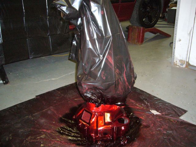
The last thread ended with the newly rebuilt TII transmission painted to match the rest of the engine bay.
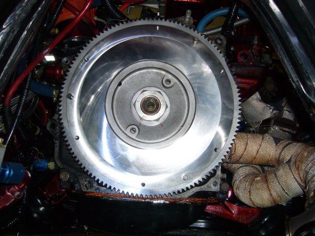
To use the TII transmission, I needed to swap the NA flywheel for the TII flywheel. As a general rule, everything behind the rear iron must match the transmission. I picked up this TII flywheel at the same time I purchased the TII transmission and then had the flywheel turned at a local auto parts store. Whenever I bring them a rotary flywheel they always think it is from a VW Beetle, no idea why as I've never seen a VW Beetle flywheel.
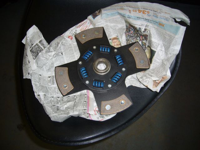
I ran a copper puck clutch before which worked fine but it did wear out quickly in daily driver duty. After speaking with the clutch guy, he recommended a Kevlar clutch for my power level and use, so that's what I ended up with.
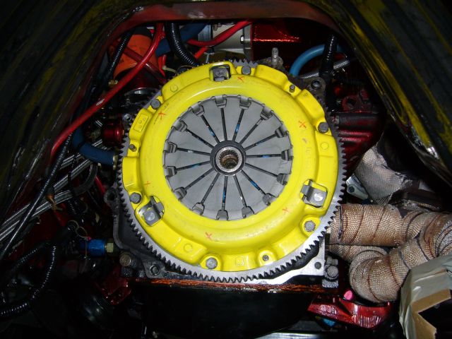
A modified stock pressure plate came with the clutch and is spec'ed to have a 30% clamping power increase. That was installed along with a new pilot bearing and seal. One day I will buy a pilot bearing puller because I am so seriously sick of grinding those things out with a Dremel. Not a big deal to do when an engine is on a stand, but not so much fun when the engine is in the car.
That that point, the transmission slid right on with a little wiggling. Since I was ordering some stuff from Mazdatrix, I also picked up a TII transmission mount. However the NA mount can be used easily by just elongating the mounting holes. In fact, it appears that both mounts are exactly the same, with oval shaped holes. Mazda just welds on a plate to close off part of the hole depending on whether they are producing NA or TII mounts.
The last thread ended with the newly rebuilt TII transmission painted to match the rest of the engine bay.
To use the TII transmission, I needed to swap the NA flywheel for the TII flywheel. As a general rule, everything behind the rear iron must match the transmission. I picked up this TII flywheel at the same time I purchased the TII transmission and then had the flywheel turned at a local auto parts store. Whenever I bring them a rotary flywheel they always think it is from a VW Beetle, no idea why as I've never seen a VW Beetle flywheel.
I ran a copper puck clutch before which worked fine but it did wear out quickly in daily driver duty. After speaking with the clutch guy, he recommended a Kevlar clutch for my power level and use, so that's what I ended up with.
A modified stock pressure plate came with the clutch and is spec'ed to have a 30% clamping power increase. That was installed along with a new pilot bearing and seal. One day I will buy a pilot bearing puller because I am so seriously sick of grinding those things out with a Dremel. Not a big deal to do when an engine is on a stand, but not so much fun when the engine is in the car.
That that point, the transmission slid right on with a little wiggling. Since I was ordering some stuff from Mazdatrix, I also picked up a TII transmission mount. However the NA mount can be used easily by just elongating the mounting holes. In fact, it appears that both mounts are exactly the same, with oval shaped holes. Mazda just welds on a plate to close off part of the hole depending on whether they are producing NA or TII mounts.
Thread Starter
Joined: Feb 2001
Posts: 29,798
Likes: 128
From: London, Ontario, Canada
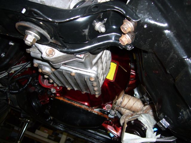
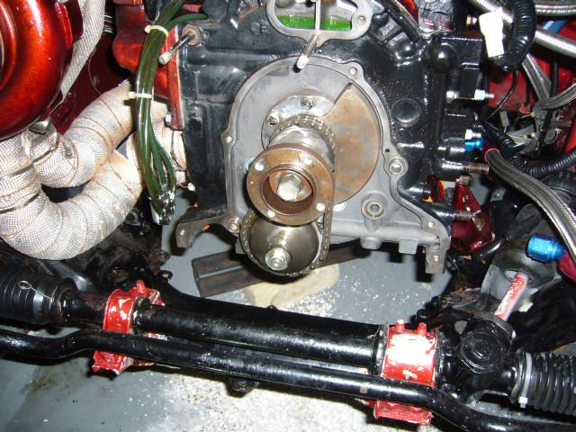
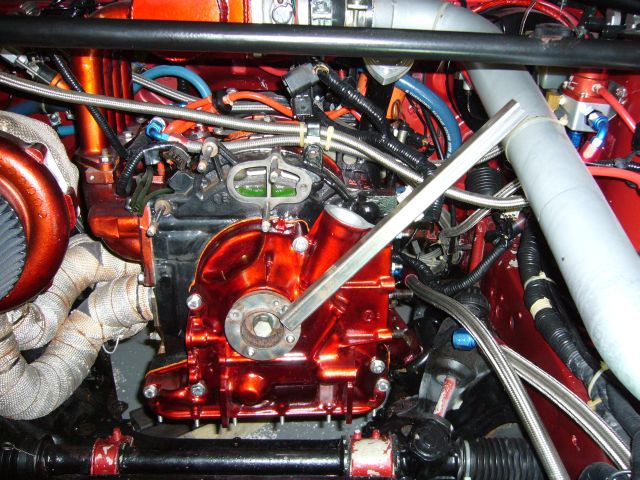
With the rear of the engine supported again by the transmission it was time to solve a problem that has been bothering me since I first started the car. For whatever reason, the front hub leaked oil past the hub bolt. This could have been caused by improper installation of the o-ring on the bottom of the bolt or the copper crush washer that seals the face of it. Either way, it ended up leaking a drop or so of oil ever 10 minutes which kept making a mess of the engine bay. Due to the location of the e-fan and rad I had been putting off fixing this but since I also wanted to upgrade the oil pump (more on that below), the front cover (and thus the hub bolt) was coming off anyway.
When I built this engine I performed the Weber jet eccentric shaft oil jet mod. The mod increases cooling oil flow to the interior of the rotors, which is especially important in a high compression turbo engine. But the downside is that with the NA oil pump, this will drastically lower idle and low RPM oil pressure. The NA pump just doesn't have the volume at these low speeds to keep the pressure up with so much oil being sprayed on the interior of the rotors. Consequently, I had around 5 PSI of oil pressure at idle and 20 PSI at 3000 RPM. As you can see in the image below, the TII oil pump on the left has much larger rotors then the NA oil pump on the right, and thus moves a lot more oil. Installation of this pump will correct the low RPM oil pressure problem.
For a little while I considered converting to a full dry sump system and began making a list of parts required and pricing out pumps. However, it took only a little longer before I realized going to dry sump would be rather stupid on a street car. The belt driven dry sump pump would be far less reliable then the stock oil pump unless I spent a lot of effort modifying the front cover for a fully enclosed chain drive or spent a tonne of money on the Mazdacomp dry sump front cover.
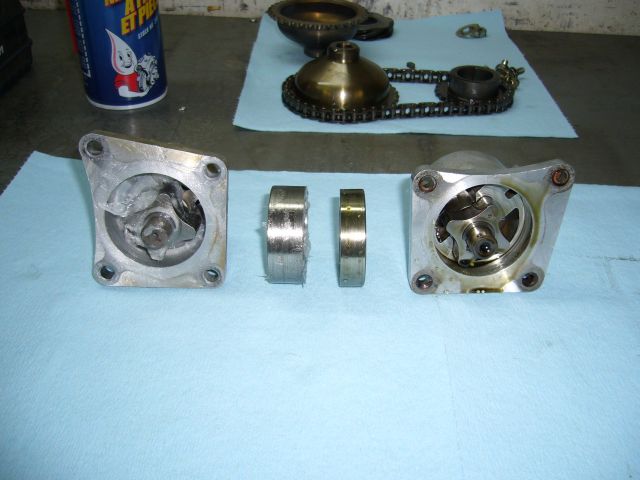
The TII oil pump is a direct bolt on upgrade to all 2nd gen NA blocks. Note that it won't fit earlier 13B or 12A blocks, the mounting holes are different.
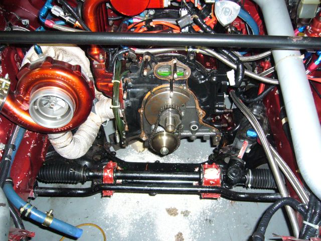
With the drive sprockets and chain reinstalled, the front hub can be snugged down to prevent potential disasters involving the spacer and torrington bearings.
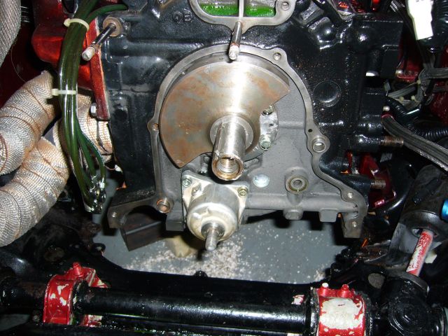
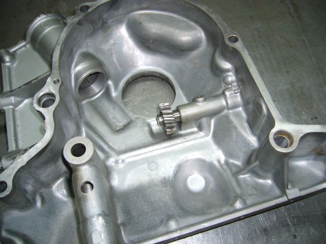
Shown here is the underside of the front cover, exposing the metering oil pump drive gear. While the front cover was off I decided that I would remove all this stuff and convert to premix. Now, I find premix to be a big pain in the ***. But a larger pain in the *** was trying to interface the 80MM Mustang throttle body I have on my custom intake to the metering oil pump. After trying 4 different methods involving cables and rods I had just given up and started premixing. Additionally, my rebuilt metering oil lines were leaking again and while I have a new set of Mazda lines on hand, I just didn't feel like messing with it anymore. Ultimately I will be making an automatic premixing system which automatically adds the appropriate amount of premix every time the car is refuelled.
When I built this engine I performed the Weber jet eccentric shaft oil jet mod. The mod increases cooling oil flow to the interior of the rotors, which is especially important in a high compression turbo engine. But the downside is that with the NA oil pump, this will drastically lower idle and low RPM oil pressure. The NA pump just doesn't have the volume at these low speeds to keep the pressure up with so much oil being sprayed on the interior of the rotors. Consequently, I had around 5 PSI of oil pressure at idle and 20 PSI at 3000 RPM. As you can see in the image below, the TII oil pump on the left has much larger rotors then the NA oil pump on the right, and thus moves a lot more oil. Installation of this pump will correct the low RPM oil pressure problem.
For a little while I considered converting to a full dry sump system and began making a list of parts required and pricing out pumps. However, it took only a little longer before I realized going to dry sump would be rather stupid on a street car. The belt driven dry sump pump would be far less reliable then the stock oil pump unless I spent a lot of effort modifying the front cover for a fully enclosed chain drive or spent a tonne of money on the Mazdacomp dry sump front cover.
The TII oil pump is a direct bolt on upgrade to all 2nd gen NA blocks. Note that it won't fit earlier 13B or 12A blocks, the mounting holes are different.
With the drive sprockets and chain reinstalled, the front hub can be snugged down to prevent potential disasters involving the spacer and torrington bearings.
Shown here is the underside of the front cover, exposing the metering oil pump drive gear. While the front cover was off I decided that I would remove all this stuff and convert to premix. Now, I find premix to be a big pain in the ***. But a larger pain in the *** was trying to interface the 80MM Mustang throttle body I have on my custom intake to the metering oil pump. After trying 4 different methods involving cables and rods I had just given up and started premixing. Additionally, my rebuilt metering oil lines were leaking again and while I have a new set of Mazda lines on hand, I just didn't feel like messing with it anymore. Ultimately I will be making an automatic premixing system which automatically adds the appropriate amount of premix every time the car is refuelled.
Thread Starter
Joined: Feb 2001
Posts: 29,798
Likes: 128
From: London, Ontario, Canada
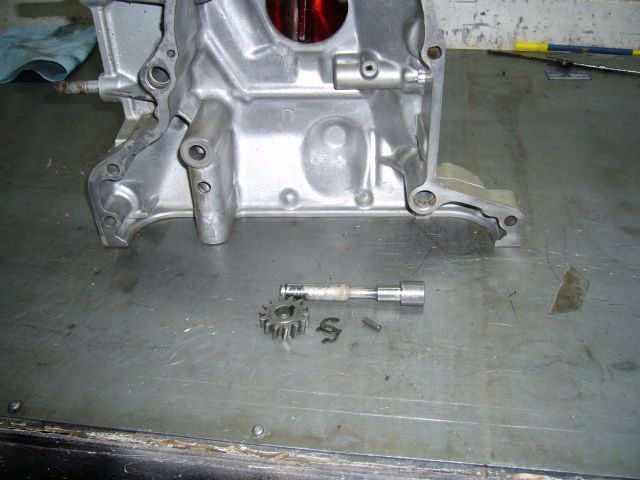
The drive gear and shaft comes out quite easily once the two snap rings are removed.
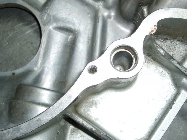
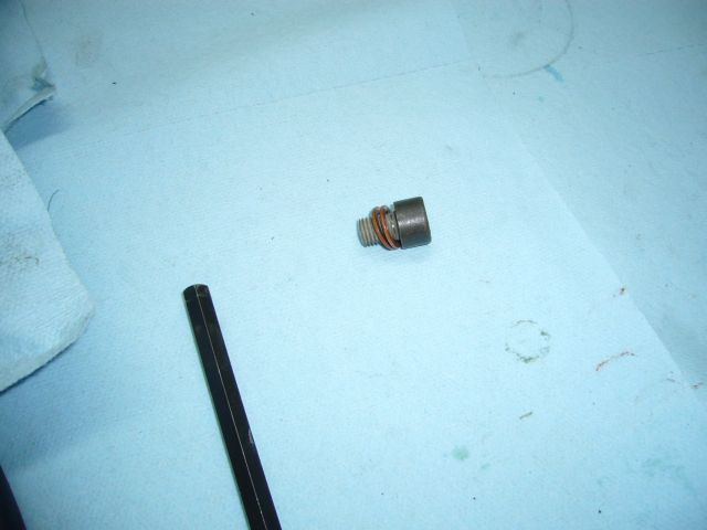
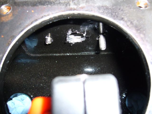
Once the MOP drive shaft is removed, the passage that feeds the shaft with oil must be plugged. If it is left open then all that oil will just spray uselessly under the front cover and likely cause a fairly severe low RPM drop in oil pressure. The stock size of this hole is sized perfectly to be tapped for 1/4" course threads. A grub screw can then be installed.
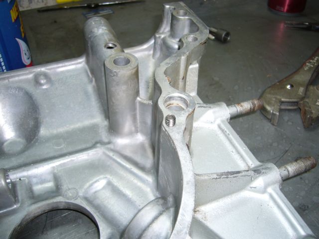
After the hole is tapped, the grub screw threads right in and sits below the surface.
I did the same thing to the feed hole on the metering oil pump flange.
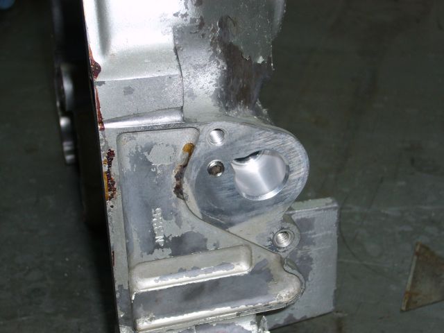
Finally, the big metering oil pump shaft hole was filled with JB Weld. This, in addition to the standard block off plate, will virtually eliminate the possibility of a leak.
I should mention that this was my second choice in how to accomplish this. On my original front cover I ground off all of the metering oil pump related castings and then shaved down the area by welding in sheet metal. A little grinding and some more welding and it looked as if the front cover was cast that way at the factory. The problem is that during the welding process, the cover became distorted and would no longer fit the engine. It was only off by about 0.5MM, but that was enough to stop it from fitting over the dowels on the front iron. Clearancing it to fit was not an option since that may shift the position of the eccentric shaft hole and CAS area.
Once the MOP drive shaft is removed, the passage that feeds the shaft with oil must be plugged. If it is left open then all that oil will just spray uselessly under the front cover and likely cause a fairly severe low RPM drop in oil pressure. The stock size of this hole is sized perfectly to be tapped for 1/4" course threads. A grub screw can then be installed.
After the hole is tapped, the grub screw threads right in and sits below the surface.
I did the same thing to the feed hole on the metering oil pump flange.
Finally, the big metering oil pump shaft hole was filled with JB Weld. This, in addition to the standard block off plate, will virtually eliminate the possibility of a leak.
I should mention that this was my second choice in how to accomplish this. On my original front cover I ground off all of the metering oil pump related castings and then shaved down the area by welding in sheet metal. A little grinding and some more welding and it looked as if the front cover was cast that way at the factory. The problem is that during the welding process, the cover became distorted and would no longer fit the engine. It was only off by about 0.5MM, but that was enough to stop it from fitting over the dowels on the front iron. Clearancing it to fit was not an option since that may shift the position of the eccentric shaft hole and CAS area.
Thread Starter
Joined: Feb 2001
Posts: 29,798
Likes: 128
From: London, Ontario, Canada
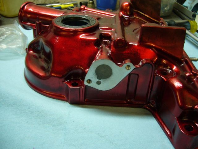
The other end of the oil passage was also filled with JB Weld after the grub screw was installed. This is so the gasket will have more area to seal against.
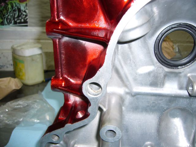
With all the work on the front cover complete, it was repainted and reinstalled on the engine. Note my custom made front hub holder tool. It's made of the little ring inside the stock pulleys and a spare length of square 1" tubing. Also notice that I installed studs on the bottom of the front cover. This makes it a hell of a lot easier to install the oil pan (and oil baffle plate) from underneath the car as you can hook the front on the studs after sticking the gasket in place with sealant.
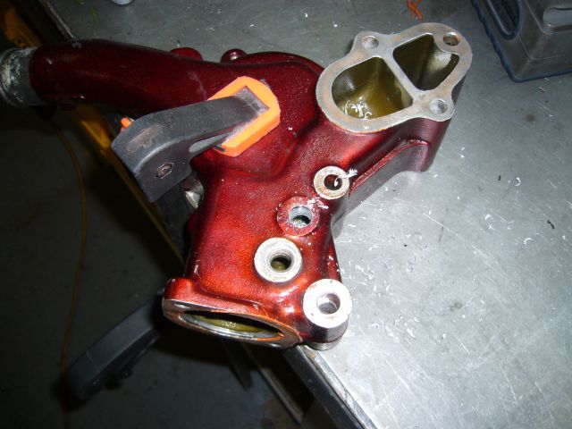
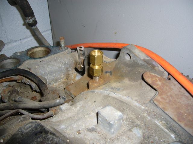
Another area of the engine that bothered me was the Push Lock tubing I used to feed coolant to the turbo. The only reason I used it originally was because I didn't think of removing the stock water nipples and tap them for AN fittings. It was a silly oversight on my part. Since the water pump housing was removed for the front cover job it was a perfect time to fix this. I yanked the stock metal nipple out of the back of the water pump housing with a big set of Vice Grips, and then drilled and tapped it for 1/4" NPT.
Testing the new hole with a spare brass 1/4" NPT fitting.
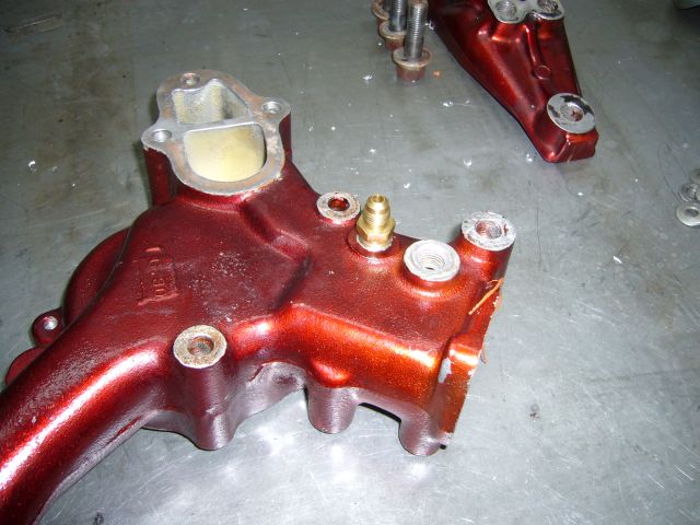
After the water pump housing was tapped, it was repainted and then all of the front engine stuff was reinstalled.
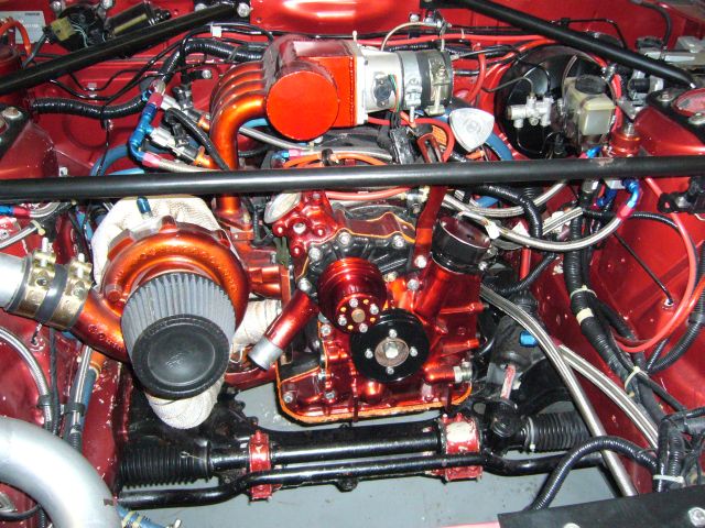
With all the work on the front cover complete, it was repainted and reinstalled on the engine. Note my custom made front hub holder tool. It's made of the little ring inside the stock pulleys and a spare length of square 1" tubing. Also notice that I installed studs on the bottom of the front cover. This makes it a hell of a lot easier to install the oil pan (and oil baffle plate) from underneath the car as you can hook the front on the studs after sticking the gasket in place with sealant.
Another area of the engine that bothered me was the Push Lock tubing I used to feed coolant to the turbo. The only reason I used it originally was because I didn't think of removing the stock water nipples and tap them for AN fittings. It was a silly oversight on my part. Since the water pump housing was removed for the front cover job it was a perfect time to fix this. I yanked the stock metal nipple out of the back of the water pump housing with a big set of Vice Grips, and then drilled and tapped it for 1/4" NPT.
Testing the new hole with a spare brass 1/4" NPT fitting.
After the water pump housing was tapped, it was repainted and then all of the front engine stuff was reinstalled.
Thread Starter
Joined: Feb 2001
Posts: 29,798
Likes: 128
From: London, Ontario, Canada
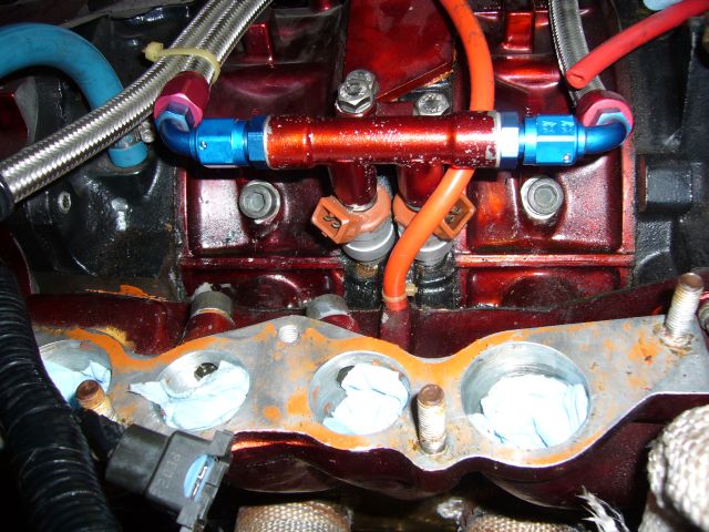
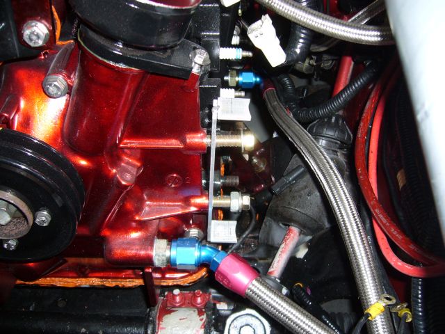
I next pulled the upper intake manifold so I could gain access to the top of the engine. The bolts shown below will be used to plug the stock metering oil holes. I forget what thread they are exactly as I just took my metering oil nozzles to the fastener store and picked up some bolts to match, then I trimmed the length down fit the engine.
The bolts were then installed with copper crush washers and pipe dope to seal them up.
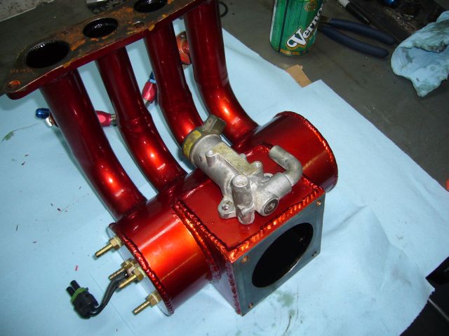
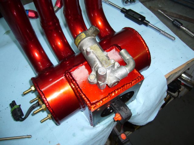
When I originally built my upper intake manifold and purchased my Microtech LT8s, I figured the car would be idling high enough that I wouldn't need a BAC valve. Oh, how wrong I was. It is always nice to have a BAC valve. Always. I was really missing the high cold idle and proper warm idle regulation that a BAC can provide so I sent my Microtech off to Australia to have the BAC control option fitted and set about adding a BAC valve to my custom manifold. I decided to mount the BAC valve to the bottom of the throttle body plenum, mainly because that as the only place I could actually fit it.
The marker traces for the mounting location and bolt holes look like a friendly happy face with a comically large nose.
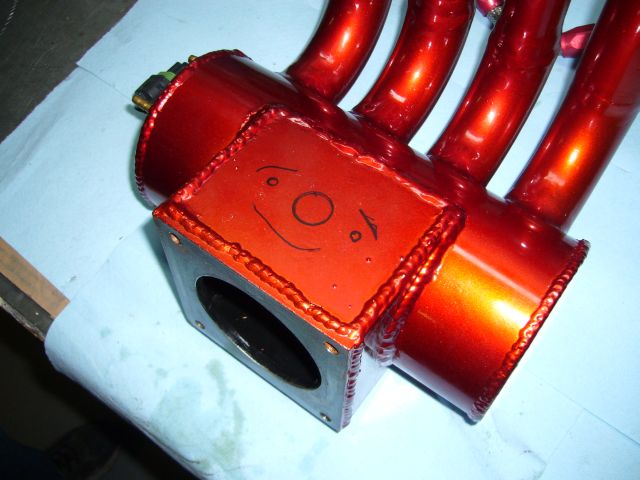
After making all the necessary holes, the BAC was bolted in place for a test fit. There was just enough metal thickness on the floor of the intake manifold to tap the holes for fine threaded M6 bolts.
The bolts were then installed with copper crush washers and pipe dope to seal them up.
When I originally built my upper intake manifold and purchased my Microtech LT8s, I figured the car would be idling high enough that I wouldn't need a BAC valve. Oh, how wrong I was. It is always nice to have a BAC valve. Always. I was really missing the high cold idle and proper warm idle regulation that a BAC can provide so I sent my Microtech off to Australia to have the BAC control option fitted and set about adding a BAC valve to my custom manifold. I decided to mount the BAC valve to the bottom of the throttle body plenum, mainly because that as the only place I could actually fit it.
The marker traces for the mounting location and bolt holes look like a friendly happy face with a comically large nose.
After making all the necessary holes, the BAC was bolted in place for a test fit. There was just enough metal thickness on the floor of the intake manifold to tap the holes for fine threaded M6 bolts.
Thread Starter
Joined: Feb 2001
Posts: 29,798
Likes: 128
From: London, Ontario, Canada
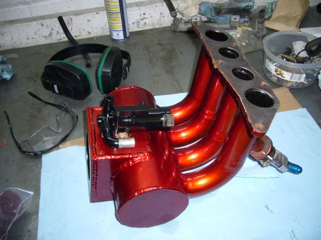
Here's a rough interior view of the main air feed hole, and the two bolt holes. The bolts used are just temporary and have not yet been shortened. Once fitment was proven, the BAC valve was painted black.
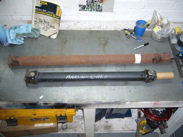
While the BAC work was being done, my custom TII transmission to NA rear end drive shaft arrived. The driveline shop (London Driveline Technology) built it out of my old shaft with a new front yolk and big Dodge truck U-joints. For comparison, a standard S4 NA driveshaft is above it on the bench.
The freshly painted BAC was then mounted on the upper intake manifold. And here is where things begin to suck...
About this time I learned from the Microtech dealer in Australia that my LT8s was "too old" to be upgraded for BAC control. Funny, Microtech promised all of us LT8s owners that our ECUs would always be upgradable. I guess that is not entirely true, and is yet another broken promise from the same company that has still not given us the promised save to disk and software upgrades that we have all been assured are only "months away" for the past 6 years. So at this point, the BAC I just installed on my intake manifold is decoration until I can figure out how to make it functional...perhaps with a Megasquirt?
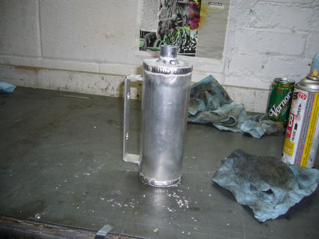
For a while I have needed a proper oil catch can. I've had an issue with blowby where oil will be forced into the PCV related vacuum hoses under boost, then sucked into the intake manifold when the throttle closes. Occasionally this will produce a cloud of smoke. So two years ago I installed a hastily made catch can that I assembled out of some plumbing pipe, which for the most part did the job. But it was too small and mounted in an odd spot (beside the charcoal canister) so sometimes, oil would get sucked out of it. A new can needed to be installed closer to the oil nipples on the center iron. I started fabricating a new can by first cutting a length of 2.5" aluminum tubing (about 7 - 8" long, I eyeballed it) and then cutting some end caps out of 3/16" aluminum.
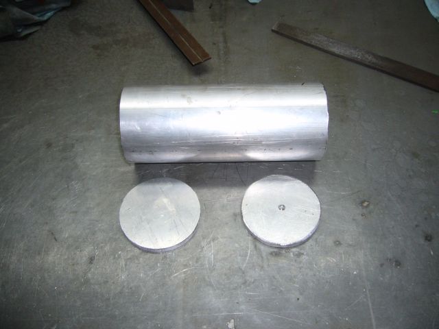
The caps were then welded to the can. Notice the relief hole I drilled in the picture above so that I was not welding a sealed cylinder. Any amount of solvent or fumes in the tubing could cause it to burst while welding if it is sealed.
While the BAC work was being done, my custom TII transmission to NA rear end drive shaft arrived. The driveline shop (London Driveline Technology) built it out of my old shaft with a new front yolk and big Dodge truck U-joints. For comparison, a standard S4 NA driveshaft is above it on the bench.
The freshly painted BAC was then mounted on the upper intake manifold. And here is where things begin to suck...
About this time I learned from the Microtech dealer in Australia that my LT8s was "too old" to be upgraded for BAC control. Funny, Microtech promised all of us LT8s owners that our ECUs would always be upgradable. I guess that is not entirely true, and is yet another broken promise from the same company that has still not given us the promised save to disk and software upgrades that we have all been assured are only "months away" for the past 6 years. So at this point, the BAC I just installed on my intake manifold is decoration until I can figure out how to make it functional...perhaps with a Megasquirt?
For a while I have needed a proper oil catch can. I've had an issue with blowby where oil will be forced into the PCV related vacuum hoses under boost, then sucked into the intake manifold when the throttle closes. Occasionally this will produce a cloud of smoke. So two years ago I installed a hastily made catch can that I assembled out of some plumbing pipe, which for the most part did the job. But it was too small and mounted in an odd spot (beside the charcoal canister) so sometimes, oil would get sucked out of it. A new can needed to be installed closer to the oil nipples on the center iron. I started fabricating a new can by first cutting a length of 2.5" aluminum tubing (about 7 - 8" long, I eyeballed it) and then cutting some end caps out of 3/16" aluminum.
The caps were then welded to the can. Notice the relief hole I drilled in the picture above so that I was not welding a sealed cylinder. Any amount of solvent or fumes in the tubing could cause it to burst while welding if it is sealed.
Thread Starter
Joined: Feb 2001
Posts: 29,798
Likes: 128
From: London, Ontario, Canada
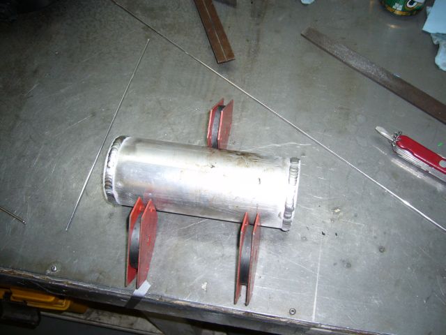
The mounting bracket was made out of some 1/8" x 1.5" bar stock I had lying around. The ends were shaped on the belt sander which happened to have exactly the same radius on it's drive drum as the catch can has.
Before I welded the bracket to the can, it was tested on the engine. It mounts to the factory power steering/AC bracket holes. The factory studs were removed and bolts used instead.
To make the top fitting on which to clamp the breather filter I just cut a short length of 1" SCH10 aluminum piping. This is actually the same pipe I used for my strut bar two years ago. The mounting bracket was welded on at the same time.
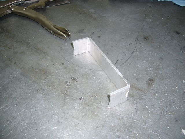
I cut some 1" pieces of 1" round aluminum bar stock to make the bungs for the fittings. They were welded in place, then drilled and tapped for 1/4" NPT. The bottom end cap was also tapped for 1/4" NPT to provide a location for the drain valve.
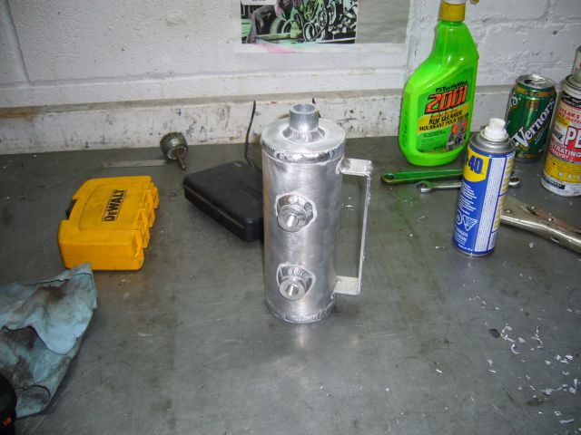
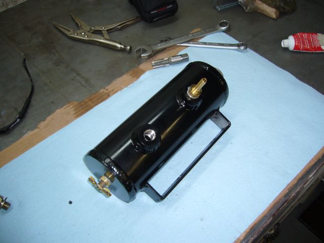
After the can was painted, all the fittings were installed. Note that the bottom bung isn't being used right now, so before I mounted the can I just put in a 1/4" pipe plug. It's always nice to have extra bung available for future use.
Before I welded the bracket to the can, it was tested on the engine. It mounts to the factory power steering/AC bracket holes. The factory studs were removed and bolts used instead.
To make the top fitting on which to clamp the breather filter I just cut a short length of 1" SCH10 aluminum piping. This is actually the same pipe I used for my strut bar two years ago. The mounting bracket was welded on at the same time.
I cut some 1" pieces of 1" round aluminum bar stock to make the bungs for the fittings. They were welded in place, then drilled and tapped for 1/4" NPT. The bottom end cap was also tapped for 1/4" NPT to provide a location for the drain valve.
After the can was painted, all the fittings were installed. Note that the bottom bung isn't being used right now, so before I mounted the can I just put in a 1/4" pipe plug. It's always nice to have extra bung available for future use.
Trending Topics
Thread Starter
Joined: Feb 2001
Posts: 29,798
Likes: 128
From: London, Ontario, Canada
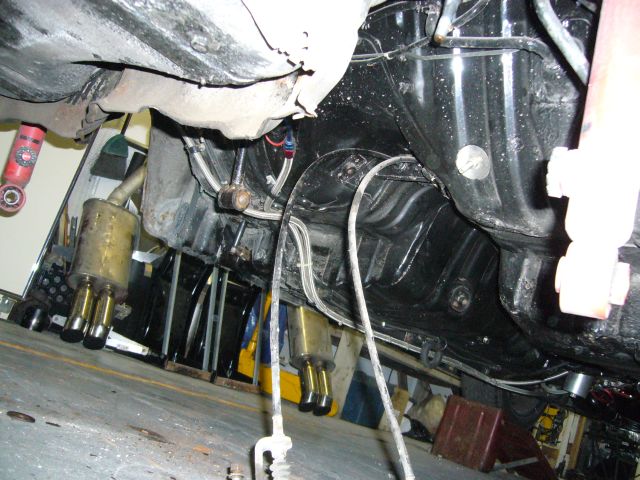
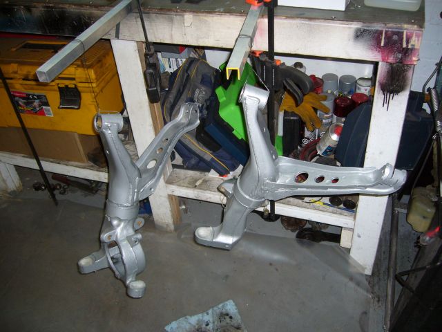
Time for some heavy lifting. My car came with an open diff, which was fine at stock power levels but at around 500HP it makes for some rather interesting driving. In fact, I'd qualify it as downright dangerous. Aside from that, there is the issue of wasting most of the power the engine is putting out in loss of traction. It is time to go to an LSD, so I sent off a spare S4 GXL LSD out to the transmission shop for a rebuild and set about pulling down the entire rear subframe. While not a particularly hard job, it is one that requires two people and multiple jacks. I also started pre-soaking most fasteners with PB Blaster a few days before and thoroughly cleaned up all the threads before attempting removal. With the subframe assembly out of the car, it was tossed up on the bench for further disassembly.
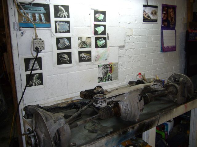
Pulling the subframe leaves a gaping hole in the rear of the car. I'll be replacing those parking brake cables since they are easy to access.
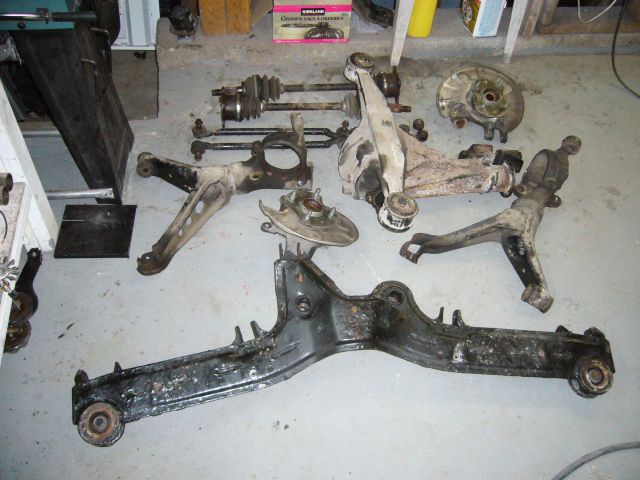
Aside from the ridiculous DTSS bushing bolts, it didn't take much effort to disassemble the rear subframe. The control arms and subframe were sent out for sand blasting, and the hub assemblies were sent to the machine shop to have the bearings replaced. The old bearings were well past worn, with almost 300K of hard driving. I won't miss the interesting noises they made while in motion. During removal, the DTSS bushings got fairly torn up so I ordered some Delrin DTSS eliminators from Mariah.
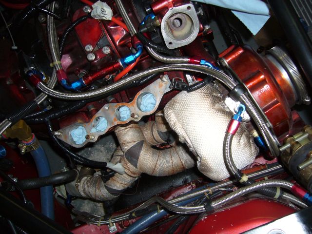
I mentioned earlier that I wanted to eliminate the crappy Push Lock hose feeding the turbo with coolant. While the water pump housing was straightforward to tap, the nipple in the rear iron was a little bit of a pickle. I could attempt to drill and tap it, but what if the thin and brittle casting cracked? That would not be good. Indeed, a friend had just managed to crack an FD rear iron trying the exact same maneuver.
The only real option was to install a compression fitting on the stock nipple, so I did a test using a spare S4 NA block that was lying around. It was already a water pumper so it's not like I could ruin it more. With a cutting wheel on the Dremel, I cut the flare off of the nipple and then smoothed it out with some emery cloth. A 3/8" compression fitting with a 1/4" NPT thread was carefully test fitted. This seemed to work out quite well. The ferrule sealed against the stock barb without any real drama. It was then time to try it for real, in the car, on my engine.
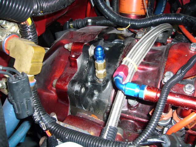
This was nerve-wracking to do, but it seems to have worked. Plenty of pipe dope was used both as lubrication and a sealant, and I spent a good amount of time with the sandpaper making sure that the nipple was smooth and fit well inside the ferrule. The AN fitting is a 1/4" NPT to -4 adapter. These compression fittings handle thousands of PSI, so I doubt there is much chance of a leak here.
If you decide to do this, I would highly recommend thinking about it before the engine is built and simply tap the iron using a standard straight thread, not a tapered pipe thread. A straight thread would be far less prone to cracking the iron. Then just seal it up with a crush washer and pipe dope.
Pulling the subframe leaves a gaping hole in the rear of the car. I'll be replacing those parking brake cables since they are easy to access.
Aside from the ridiculous DTSS bushing bolts, it didn't take much effort to disassemble the rear subframe. The control arms and subframe were sent out for sand blasting, and the hub assemblies were sent to the machine shop to have the bearings replaced. The old bearings were well past worn, with almost 300K of hard driving. I won't miss the interesting noises they made while in motion. During removal, the DTSS bushings got fairly torn up so I ordered some Delrin DTSS eliminators from Mariah.
I mentioned earlier that I wanted to eliminate the crappy Push Lock hose feeding the turbo with coolant. While the water pump housing was straightforward to tap, the nipple in the rear iron was a little bit of a pickle. I could attempt to drill and tap it, but what if the thin and brittle casting cracked? That would not be good. Indeed, a friend had just managed to crack an FD rear iron trying the exact same maneuver.
The only real option was to install a compression fitting on the stock nipple, so I did a test using a spare S4 NA block that was lying around. It was already a water pumper so it's not like I could ruin it more. With a cutting wheel on the Dremel, I cut the flare off of the nipple and then smoothed it out with some emery cloth. A 3/8" compression fitting with a 1/4" NPT thread was carefully test fitted. This seemed to work out quite well. The ferrule sealed against the stock barb without any real drama. It was then time to try it for real, in the car, on my engine.
This was nerve-wracking to do, but it seems to have worked. Plenty of pipe dope was used both as lubrication and a sealant, and I spent a good amount of time with the sandpaper making sure that the nipple was smooth and fit well inside the ferrule. The AN fitting is a 1/4" NPT to -4 adapter. These compression fittings handle thousands of PSI, so I doubt there is much chance of a leak here.
If you decide to do this, I would highly recommend thinking about it before the engine is built and simply tap the iron using a standard straight thread, not a tapered pipe thread. A straight thread would be far less prone to cracking the iron. Then just seal it up with a crush washer and pipe dope.
Thread Starter
Joined: Feb 2001
Posts: 29,798
Likes: 128
From: London, Ontario, Canada
Installing the catch can took only a few minutes. That little K&N breather filter was surprisingly expensive.
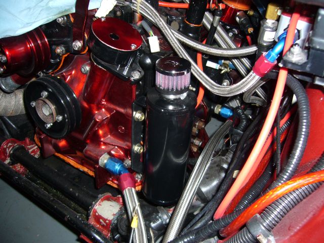
The feed nipple of the catch can connects to the nipple on the center iron at the oil filler. The nipple on the oil filler neck then connects to a vacuum port on the intake manifold through a check valve. Another check valve is inserted in the line from the center iron to the charcoal canister to prevent the center iron from blowing into the canister. This setup allows the crankcase to breath properly into the can when the car is under boost, but keeps the PCV system working when the car is under vacuum by drawing polluted air through the top nipple while fresh air fills the center iron via the bottom nipple and filter on the catch can.
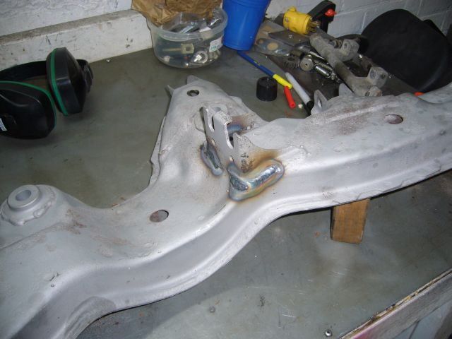
When the subframe and control arms returned from the blaster (the person doing the sand blasting was cursing my name when trying to remove the POR-15 from the bottom of the frame) I set about reinforcing the front differential mount. I've seen one of these break under power from a TII with a stock turbo, so it only made sense to take the time now to beef up the mount before it breaks later. The corners of the mount aren't welded from the factory which would seem to be a major weak point. I closed the gap between the mount and subframe with a hammer, and then laid down some welds to secure it. Look at that pretty heat-effected-zone.
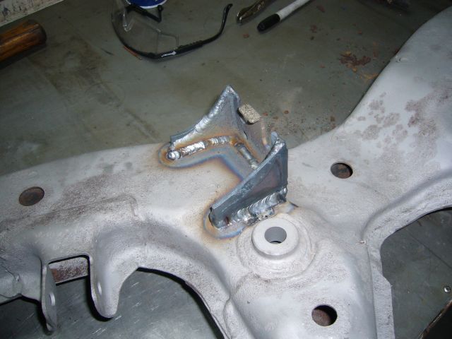
Two pieces of 1/8" plate were TIG welded to the outside of the mount, while the inner seam was simply MIG welded.
The freshly blasted control arms were degreased with Castrol Super Clean, etched by POR-15s MetalReady and then painted with two coats of silver POR-15. This is the first time I have used silver POR-15 and I must say that it is harder to use then the black I am used to. It coats thinner and is more prone to dripping. I used silver just for a bit of contrast but from now on I will stick with black. Black POR-15 also seems much stronger once cured.
The feed nipple of the catch can connects to the nipple on the center iron at the oil filler. The nipple on the oil filler neck then connects to a vacuum port on the intake manifold through a check valve. Another check valve is inserted in the line from the center iron to the charcoal canister to prevent the center iron from blowing into the canister. This setup allows the crankcase to breath properly into the can when the car is under boost, but keeps the PCV system working when the car is under vacuum by drawing polluted air through the top nipple while fresh air fills the center iron via the bottom nipple and filter on the catch can.
When the subframe and control arms returned from the blaster (the person doing the sand blasting was cursing my name when trying to remove the POR-15 from the bottom of the frame) I set about reinforcing the front differential mount. I've seen one of these break under power from a TII with a stock turbo, so it only made sense to take the time now to beef up the mount before it breaks later. The corners of the mount aren't welded from the factory which would seem to be a major weak point. I closed the gap between the mount and subframe with a hammer, and then laid down some welds to secure it. Look at that pretty heat-effected-zone.
Two pieces of 1/8" plate were TIG welded to the outside of the mount, while the inner seam was simply MIG welded.
The freshly blasted control arms were degreased with Castrol Super Clean, etched by POR-15s MetalReady and then painted with two coats of silver POR-15. This is the first time I have used silver POR-15 and I must say that it is harder to use then the black I am used to. It coats thinner and is more prone to dripping. I used silver just for a bit of contrast but from now on I will stick with black. Black POR-15 also seems much stronger once cured.
Thread Starter
Joined: Feb 2001
Posts: 29,798
Likes: 128
From: London, Ontario, Canada
The subframe was also painted in POR-15, this time properly in black.
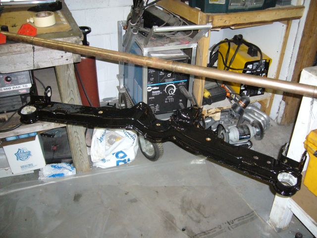
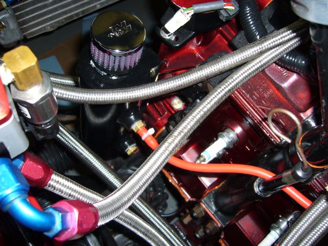
Giving the POR-15 a little time to cure, I assembled the -6 braided stainless water lines for the turbo and installed them onto the car.
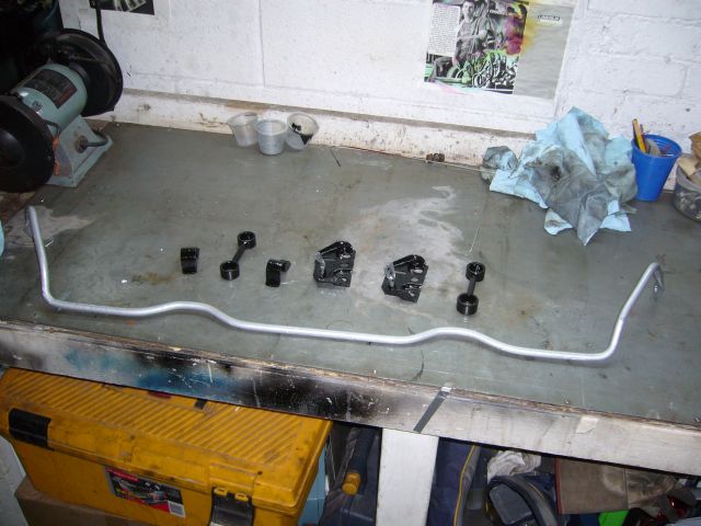
While I was painting stuff I also painted the sway bar and related hardware.
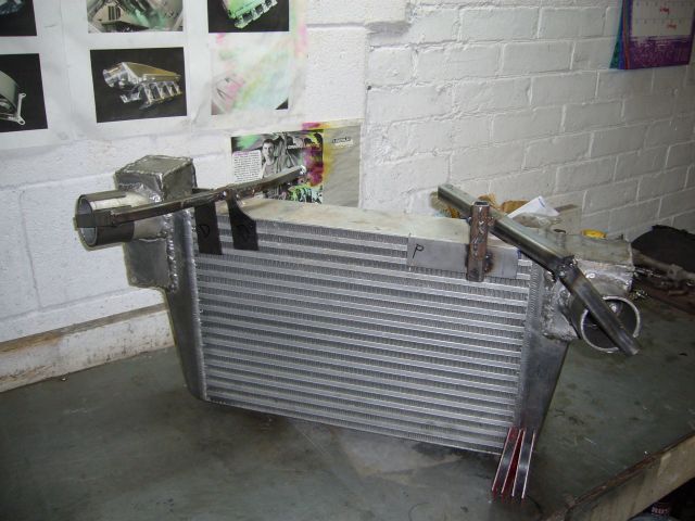
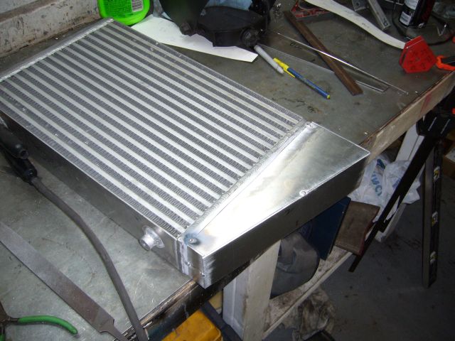
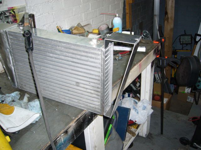
At this point I was waiting for my DTSS bushings to come from Mariah, so I figured I would correct another little annoyance with my previous work. Years ago when I modified the intercooler to change the orientation of the inlet and outlet pipes, I had only sporadic access to a TIG welder and very little practice actually using it. Consequently I tried to minimize the amount of modification done to the end tanks. While the modifications were functional (I can't complain about over 400HP at 13 PSI), they still sucked. The appearance of the intercooler bothered me every time I saw it and I didn't even want to think about mow much the hastily modified end tanks were hurting potential flow. The first step in fixing this mess was to make a set of jigs to locate the inlet and outlet pipes. I just grabbed some scrap metal from around the shop and welded up some simple bracing.
The next step was to cut off the previously added junk. I can't believe that there was a time when I actually welded that poorly. Then again, those tank modifications were made literally just after TIG welded aluminum for the first time.
Giving the POR-15 a little time to cure, I assembled the -6 braided stainless water lines for the turbo and installed them onto the car.
While I was painting stuff I also painted the sway bar and related hardware.
At this point I was waiting for my DTSS bushings to come from Mariah, so I figured I would correct another little annoyance with my previous work. Years ago when I modified the intercooler to change the orientation of the inlet and outlet pipes, I had only sporadic access to a TIG welder and very little practice actually using it. Consequently I tried to minimize the amount of modification done to the end tanks. While the modifications were functional (I can't complain about over 400HP at 13 PSI), they still sucked. The appearance of the intercooler bothered me every time I saw it and I didn't even want to think about mow much the hastily modified end tanks were hurting potential flow. The first step in fixing this mess was to make a set of jigs to locate the inlet and outlet pipes. I just grabbed some scrap metal from around the shop and welded up some simple bracing.
The next step was to cut off the previously added junk. I can't believe that there was a time when I actually welded that poorly. Then again, those tank modifications were made literally just after TIG welded aluminum for the first time.
Thread Starter
Joined: Feb 2001
Posts: 29,798
Likes: 128
From: London, Ontario, Canada
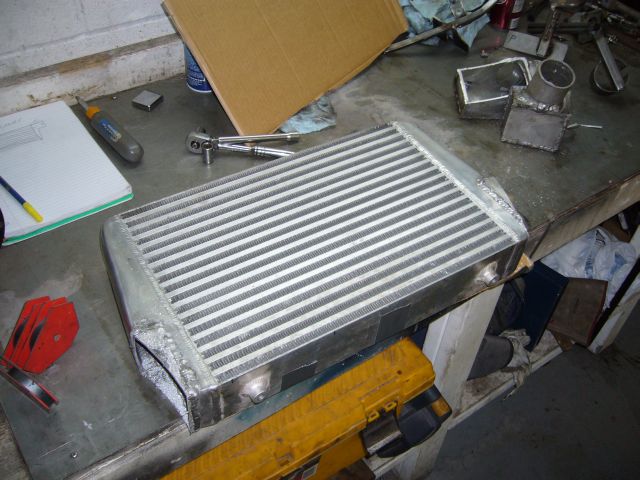
Next I ran the whole intercooler core through the band saw to cut off what remained of the factory cast end tanks.
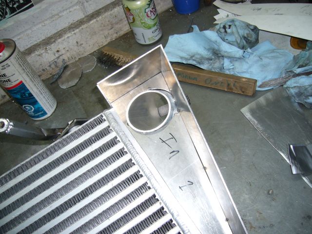
After eyeballing the correct measurements based on the location of the inlet/outlet pipe jig, I cut the outer shell of the new end tank out of 1/8" aluminum and tacked it into place. From memory, the bottom is an inch long and the top is 4 inches. This significantly increases the size of the tank and also moves the bottom out from the core quite a lot.
I made the back of the tank by tracing the pattern out of cardboard, trimming to fit, and then transferring it to aluminum. It was then tacked into place, with the last tack accidentally getting a fairly good helping of tungsten as well.
The jig was then used to measure the inlet pipe, which is made of 2.5" aluminum tubing. Here's a rare picture of me actually doing something. Normally I am on the other side of the camera but someone grabbed the camera while I was welding and decided to take a picture.
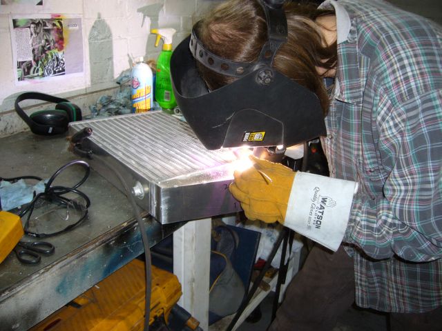
There were larger gaps then I had intended between the inlet tube and tank so it was a good thing the jig was there to stop the tubing from moving during tacking. I tacked alternating sides to help prevent movement as the welds cooled.
After eyeballing the correct measurements based on the location of the inlet/outlet pipe jig, I cut the outer shell of the new end tank out of 1/8" aluminum and tacked it into place. From memory, the bottom is an inch long and the top is 4 inches. This significantly increases the size of the tank and also moves the bottom out from the core quite a lot.
I made the back of the tank by tracing the pattern out of cardboard, trimming to fit, and then transferring it to aluminum. It was then tacked into place, with the last tack accidentally getting a fairly good helping of tungsten as well.
The jig was then used to measure the inlet pipe, which is made of 2.5" aluminum tubing. Here's a rare picture of me actually doing something. Normally I am on the other side of the camera but someone grabbed the camera while I was welding and decided to take a picture.
There were larger gaps then I had intended between the inlet tube and tank so it was a good thing the jig was there to stop the tubing from moving during tacking. I tacked alternating sides to help prevent movement as the welds cooled.
Thread Starter
Joined: Feb 2001
Posts: 29,798
Likes: 128
From: London, Ontario, Canada
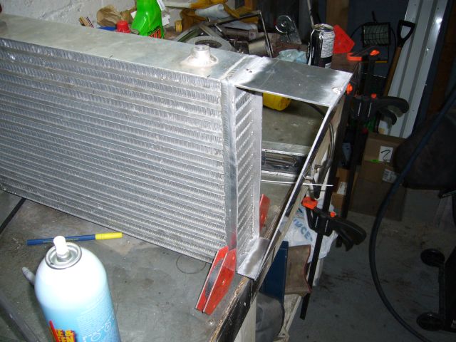
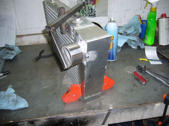
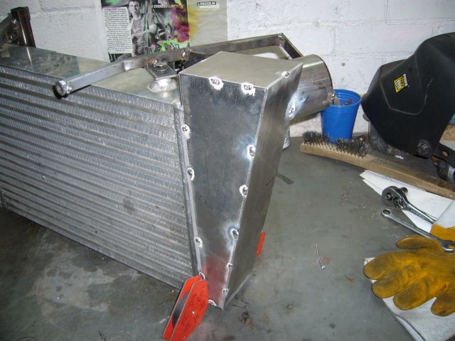
Once the tubing was tacked into place I closed up the other side. It was my goal to keep the sheet metal fitting as close as possible to avoid warping during final welding so I spent quite a bit of time with a file making everything fit. It ended up fitting well enough that only friction was required to hold it while tacking.
The other end tank was put together in the same way as the first. The only difference is that this one needed to be a bit higher due to the location of the outlet tube.
The jig was the used to locate the outlet tube. I purposely left a little bit of tubing on the inside of the end tank for a small "velocity stack" effect. Whether this will work or not, I don't know but I guess it was worth trying. With all the turbulent air already in an intercooler it can't hurt any.
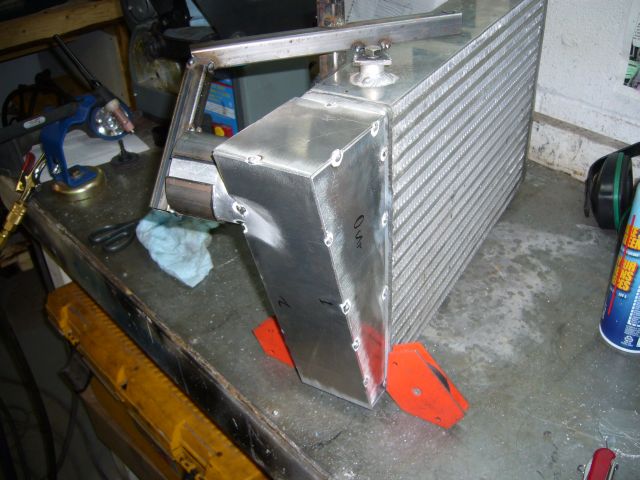
Another panel closed off the back of the drivers side tank and then the intercooler was ready to be fully welded.
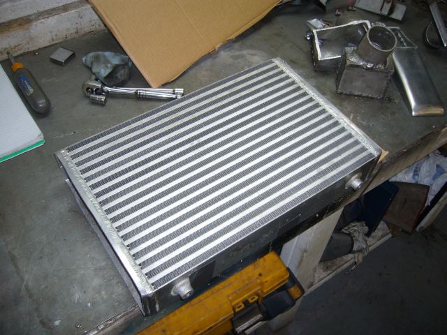
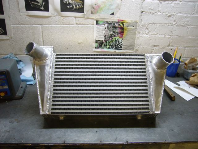
After about 2.5 hours behind the TIG torch this was the result. I must say I'm quite happy with how it came out and without question it is worlds better then what I started with. Notice that I welded little beads around the edges of the tube to make the beads which prevent the couplers from blowing off. After I took this picture I smoothed out those beads with a flap wheel, a file and sandpaper.
That was 60 pictures and I think time stop this update. I've been hard at work for a while and hope to have the rear suspension back in the car this weekend. When the rear suspension is done, I just have a few exhaust changes to make and then the front bearings and bushings to replace before the car is back on the road for the summer.
It's quite nice to be just making improvements to the car and taking care of simple maintenance items instead of building it. I would have liked to have had it out on the road earlier this spring but shipping and other delays caused me to wait. No worries though, as it will be on the road soon and I'll have the entire summer to drive it.
The other end tank was put together in the same way as the first. The only difference is that this one needed to be a bit higher due to the location of the outlet tube.
The jig was the used to locate the outlet tube. I purposely left a little bit of tubing on the inside of the end tank for a small "velocity stack" effect. Whether this will work or not, I don't know but I guess it was worth trying. With all the turbulent air already in an intercooler it can't hurt any.
Another panel closed off the back of the drivers side tank and then the intercooler was ready to be fully welded.
After about 2.5 hours behind the TIG torch this was the result. I must say I'm quite happy with how it came out and without question it is worlds better then what I started with. Notice that I welded little beads around the edges of the tube to make the beads which prevent the couplers from blowing off. After I took this picture I smoothed out those beads with a flap wheel, a file and sandpaper.
That was 60 pictures and I think time stop this update. I've been hard at work for a while and hope to have the rear suspension back in the car this weekend. When the rear suspension is done, I just have a few exhaust changes to make and then the front bearings and bushings to replace before the car is back on the road for the summer.
It's quite nice to be just making improvements to the car and taking care of simple maintenance items instead of building it. I would have liked to have had it out on the road earlier this spring but shipping and other delays caused me to wait. No worries though, as it will be on the road soon and I'll have the entire summer to drive it.
Looking good Aaron! its a smart move bracing that front diff mount bracket, i ended up ripping mine right off the subframe, and had to mess around with getting everything back in the right spot. i beefed mine up nice and good, and has held up good ever since (over 100 6k launches with drag radials)

Holy batman! Thats where you've been hiding  You know its almost time for us to do a london meet again, when do you think your car will be done by? My car need quite a bit of work also before being displayed. But I think that Boston Pizza location might have to change ... our waitress from the last meet there still seems to recognize me, so its either we go there and I might have to take her out on a date, or we could just change places lol.
You know its almost time for us to do a london meet again, when do you think your car will be done by? My car need quite a bit of work also before being displayed. But I think that Boston Pizza location might have to change ... our waitress from the last meet there still seems to recognize me, so its either we go there and I might have to take her out on a date, or we could just change places lol.


Thread Starter
Joined: Feb 2001
Posts: 29,798
Likes: 128
From: London, Ontario, Canada
Holy batman! Thats where you've been hiding You know its almost time for us to do a london meet again, when do you think your car will be done by? My car need quite a bit of work also before being displayed. But I think that Boston Pizza location might have to change ... our waitress from the last meet there still seems to recognize me, so its either we go there and I might have to take her out on a date, or we could just change places lol.
You know its almost time for us to do a london meet again, when do you think your car will be done by? My car need quite a bit of work also before being displayed. But I think that Boston Pizza location might have to change ... our waitress from the last meet there still seems to recognize me, so its either we go there and I might have to take her out on a date, or we could just change places lol.Absolutely. I'm hoping to be at the May meet. Once the RX-7 is on the road again, it is finally time to start restoring my Cosmo. Also, the Insight might see paint as well.

Aaron you should think about using a 3" glass pack as a resonator instead of adding another resonator, it quiets it down a bit and gives it a nice sound
thats what i use i like the tone it adds compared to my straight pipe or Louis's 3" with just the resonator
Exhaust direct makes them in house, i think i paid like $25-30 for mine
thats what i use i like the tone it adds compared to my straight pipe or Louis's 3" with just the resonator
Exhaust direct makes them in house, i think i paid like $25-30 for mine
Thread Starter
Joined: Feb 2001
Posts: 29,798
Likes: 128
From: London, Ontario, Canada
 I'll take a bike or scooter ride down the path in the next week and see if there are some good spots slightly out of the way with ample parking, a BBQ pit, etc.
Thank you. I originally welded in the intercooler many years ago on a massive old 300A Canox TIG welder. Low range didn't seem to work so I had to use medium range, and I learned afterwards that the high frequency circuit was not working either. So here I am, my first TIG experience, running a torch that was WAY too hot with virtually no arc stability, a huge water cooled torch and a set of dirty filler rods. Nowadays I have a lot more hours behind the torch and my little Miller Econotig works just fine.
Aaron you should think about using a 3" glass pack as a resonator instead of adding another resonator, it quiets it down a bit and gives it a nice sound
thats what i use i like the tone it adds compared to my straight pipe or Louis's 3" with just the resonator
Exhaust direct makes them in house, i think i paid like $25-30 for mine
thats what i use i like the tone it adds compared to my straight pipe or Louis's 3" with just the resonator
Exhaust direct makes them in house, i think i paid like $25-30 for mine
The only problem with glass packs behind a rotary is that they tend to burn out. Some last only a few hours, while others last much longer. But I bet you will find that after a few months, much of the packing has melted out of your resonator.
This is what I do.