Project IIc: The road to 350 rwhp

 03-31-15, 05:15 PM
#52


Wow Thanks! I've seen your work and a compliment from you means a lot. Keep up the fabrications!
I've been thinking a bit more about my build goals. Ultimately the plan hasn't changed and I want to achieve a clean weekend car with some nice power behind it. But I don't think I can endure another winter without putting the wheels on the road. My schedule at work will be a little bit lighter; however, money is still tight. I'd like to get the car in driving shape before next winter hits. I have $2500 saved and here is my plan:
1. Complete the engine rebuild (Atkins rebuild kit with OEM seals $1500)
2. Put the engine and transmission back in which requires a new clutch kit and flywheel ($~600)
3. Wire up the standalone; I'm going with Adaptronics E420D since Elliot at Turblown is about an hour away ($1000)
4. Upgrade the fuel injectors; I'd like to go with Injector Dynamics 725 primary and 1300 secondary (~400)
These are the ESSENTIALS. The must have's before I can get the car back in running conditions. For the rest of the parts, I can use the old ones to get the car running and then upgrade little by little during next winter. Unfortunately my total is more expensive than my budget... and I have to figure out where I can get the extra cash. My hope is to get the car running and just put enough miles on it to break in the engine and get a base map tune for the ECU. Then next summer, I'd be able to start boosting it and get it tuned by Elliot.
03-31-15, 08:15 PM
#53
Rotary Enthusiast
iTrader: (1)

Join Date: Nov 2012
Location: bloomington, mn
Posts: 1,100
Likes: 0
Received 0 Likes
on
0 Posts
While most people in this state praise Elliot, and he is "the states only tuner" *rolls eyes* I have outsourced everything he can get sooo much cheaper from other vendors shipped to my door. Hell, I am not even going to him for tuning because of some smart *** comments he made.
Keep plugging away though, and feel free to ask for help.
Keep plugging away though, and feel free to ask for help.
 04-02-15, 03:27 PM
#55
Full Member
Thread Starter
iTrader: (3)
Join Date: Mar 2013
Location: Minnesota
Posts: 54
Likes: 0
Received 0 Likes
on
0 Posts
While most people in this state praise Elliot, and he is "the states only tuner" *rolls eyes* I have outsourced everything he can get sooo much cheaper from other vendors shipped to my door. Hell, I am not even going to him for tuning because of some smart *** comments he made.
Keep plugging away though, and feel free to ask for help.
Keep plugging away though, and feel free to ask for help.
This weekend I'm going to try and do the final cleaning of the engine parts, bathe them in WD-40 and store them until I order my rebuild kit. Then I'm going to start cleaning the engine bay and get it ready. I decided to clean up the front harness as well. I'll be using the following write up as a guide: http://www.norotors.com/index.php?topic=2874.0
Last edited by Thepersian; 04-02-15 at 03:30 PM.
04-02-15, 10:48 PM
#56
Rotary Enthusiast
iTrader: (1)
Join Date: Nov 2012
Location: bloomington, mn
Posts: 1,100
Likes: 0
Received 0 Likes
on
0 Posts
ironically enough, the tuning section on this forum has SOOO much info on getting things to a base if not stable tune with some time researching things. You will be ready for a tune before I will be, other wise I would split transport to a steve kahn session.
04-05-15, 09:36 PM
#57
Full Member
Thread Starter
iTrader: (3)
Join Date: Mar 2013
Location: Minnesota
Posts: 54
Likes: 0
Received 0 Likes
on
0 Posts
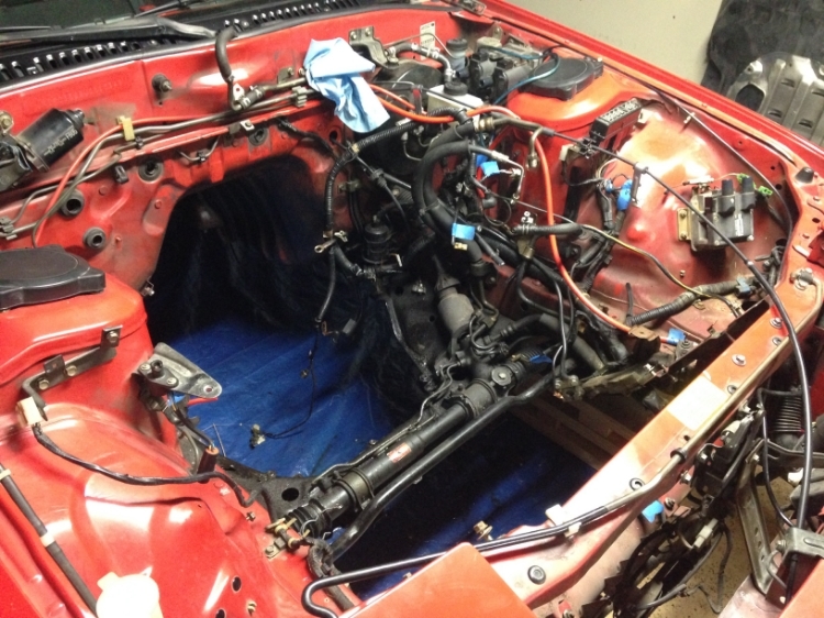
So this weekend I got bored and wanted to do something with the car...
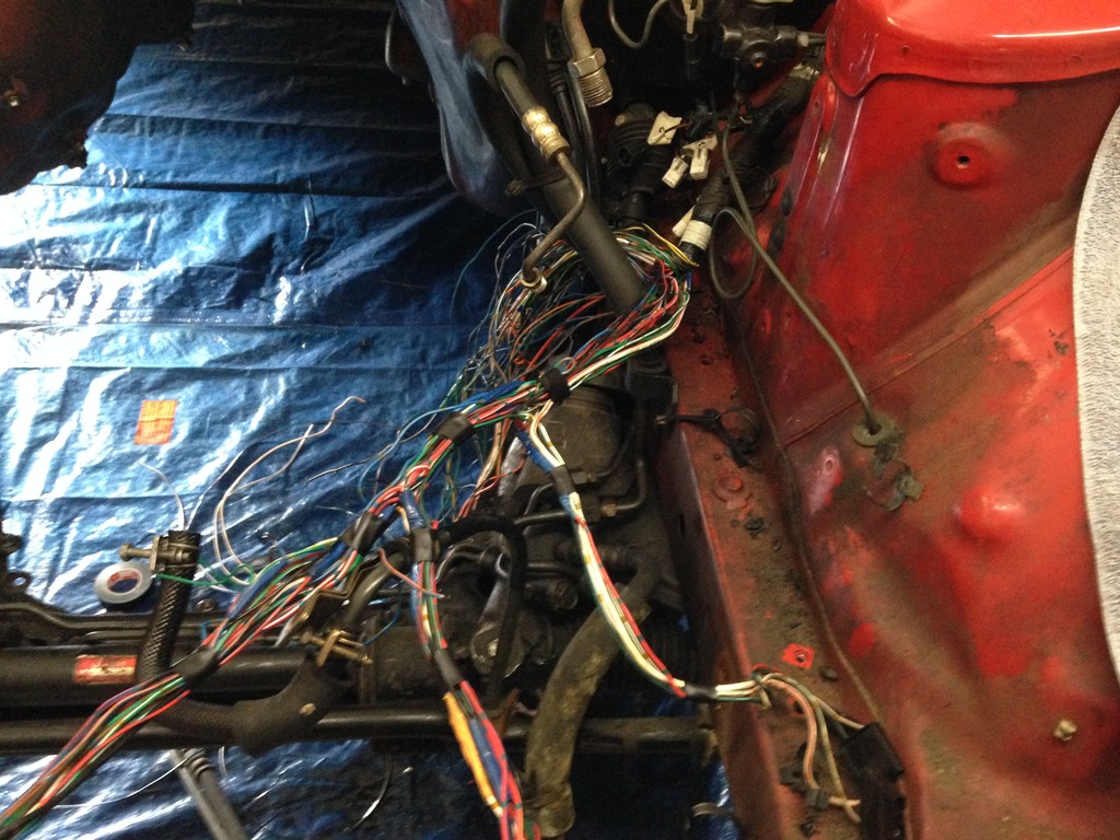
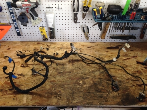
This is what my engine bay looked like before. I didn't like how the Front Harness made it look so messy. Additionally, there were crevasses behind the harness that the paint had chipped away and the metal had started to rust; another reason to do the "tuck".
Before:
I started by making a diagram of which connectors to keep and which ones to cut. I took lots of pictures and labelled everything in case I had to go back and check my work. Then I started from the most distal part and slowly peeled away the tape, cut the connectors with a short tail and separated the harness away from the cut wires...
My fingernail beds were getting sore at this point...
Some more on Easter Sunday...
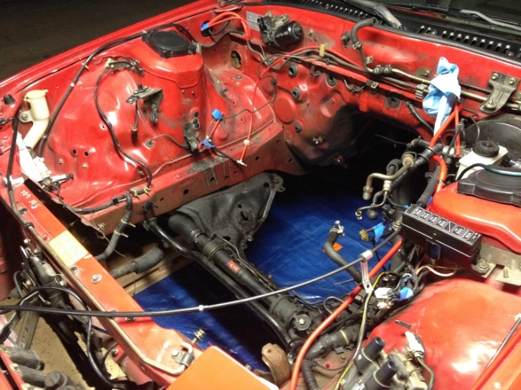
And finally I got down to the grommet with two nicely separated sets of wires. The one on the left is usable harness and the right is just junk. To keep things nice and neat, I periodically used a bit of electrical tape to organize the harness.
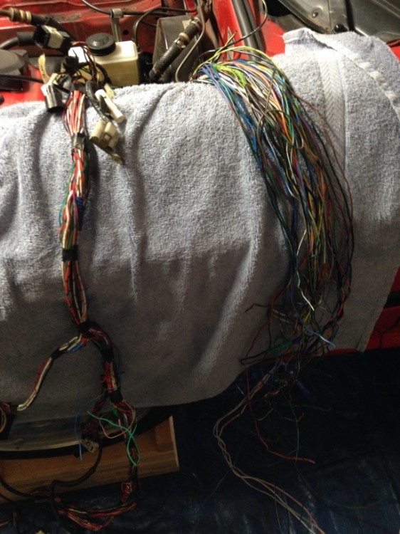
After:
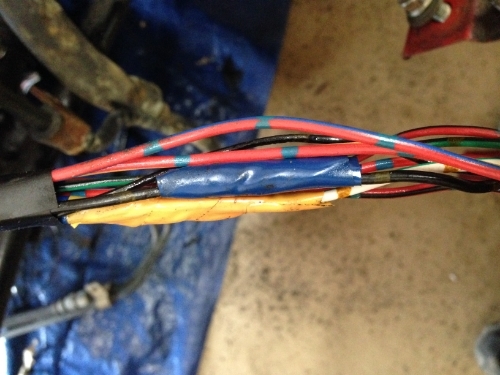
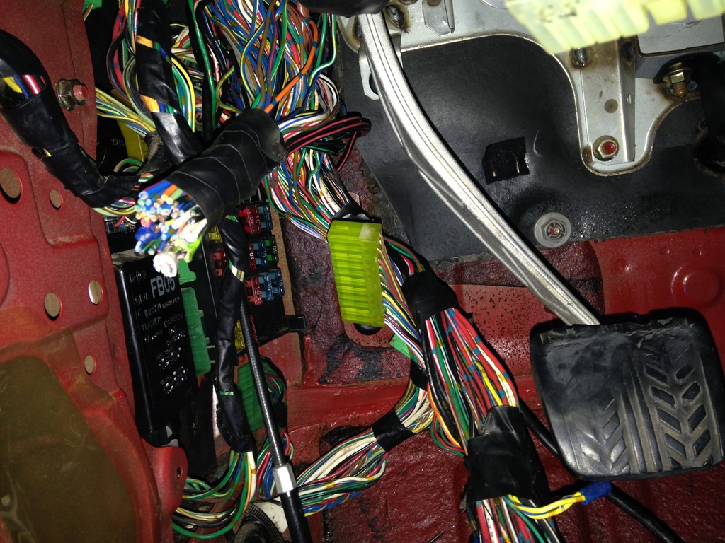
Just imagine how much cleaner the bay will look after I give it a nice scrub-down and remove the power steering lines. I did make a couple of small mistakes along the way, nothing major that I can't solder. There were a few connections that need to be made to keep the wiring harness functional. I'll try and post a nice diagram with labels later for anyone else who wants to do this. At this point I have the harness at the grommet. I'll need to push it into the car and drill a hole in the wheel well to route the harness under the car and out of sight. Just look at my last post; which I linked a nice guide for doing this "tuck." Before I do the final rewrapping and tucking, I'll check the system to make sure that all the connections are still working. One thing to note is that there is a crimped connection and/or a T connection at every colored tape along the harness. I'll be removing all these tapes and resoldering and heat shrinking every connection to make sure it lasts. Here is an example of what I'm talking about:
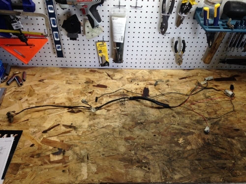
I also cleaned up the "Engine" harness since I'll be relocating the battery and running fresh wires to the charging system.
Before...
After...
 04-05-15, 09:41 PM
#58
Full Member
Thread Starter
iTrader: (3)
Join Date: Mar 2013
Location: Minnesota
Posts: 54
Likes: 0
Received 0 Likes
on
0 Posts
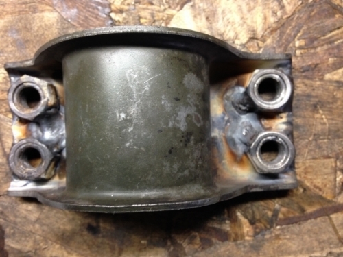
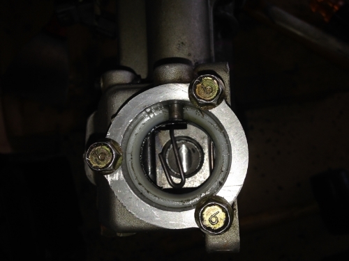
Water pump modification
Earlier this week I got a few things that came in the mail.
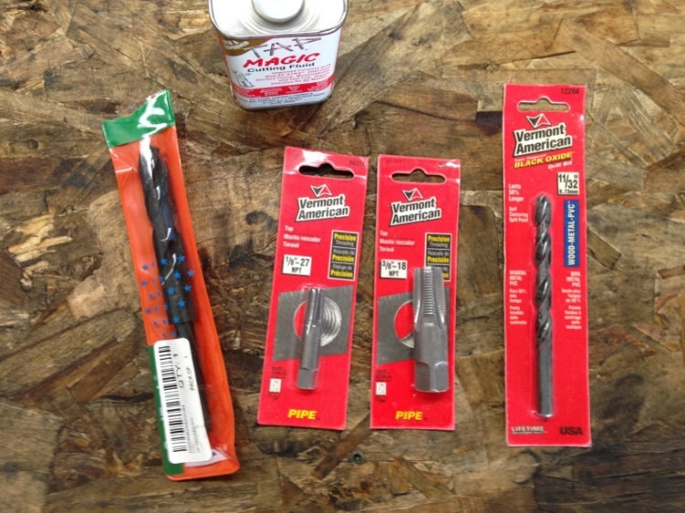
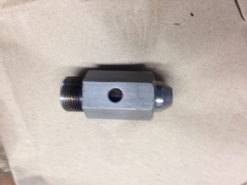
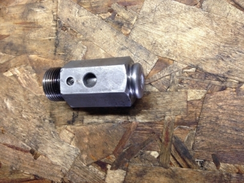
Which I used to turn this...
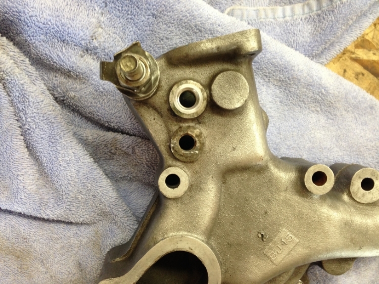
into this...
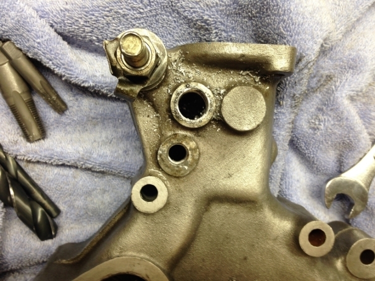
The top hole used to be the OE water thermo sensor hole. I drilled and tapped it for 3/8" npt; which I'll be using a GM type coolant temperature sensor for the standalone ECU. Just to the bottom of that was the old feed line to the throttle body warm up idle wax. I removed the barbed hose and tapped it for 1/8" npt; which I'll be using to install the sensor to my aftermarket water temperature gauge. The hole was a tiny bit too big for a good tap but I'll see if I have any issues with a leak once I start the system. If I do have a leak at that point, I can easily reinforce it with a washer. Also, another issue that can rise is the gauge sensor protrudes into the water pump housing much deeper than the ECU one which may result in splitting the stream and causing poor contact between the coolant and the sensor. I'll check the variability between the two sensors once everything is installed and running. If that issue occurs, I have a pretty good idea of fixing it. This way I can monitor the coolant temperature before the thermostat; which means I have continuous reading of the water temperature. The old gauge sensor used to sit after the thermostat and would just jump from 0 to 160 degrees when the thermostat opened; not critical since it's the gauge sensor but it bothered me.
Which I used to turn this...
into this...
The top hole used to be the OE water thermo sensor hole. I drilled and tapped it for 3/8" npt; which I'll be using a GM type coolant temperature sensor for the standalone ECU. Just to the bottom of that was the old feed line to the throttle body warm up idle wax. I removed the barbed hose and tapped it for 1/8" npt; which I'll be using to install the sensor to my aftermarket water temperature gauge. The hole was a tiny bit too big for a good tap but I'll see if I have any issues with a leak once I start the system. If I do have a leak at that point, I can easily reinforce it with a washer. Also, another issue that can rise is the gauge sensor protrudes into the water pump housing much deeper than the ECU one which may result in splitting the stream and causing poor contact between the coolant and the sensor. I'll check the variability between the two sensors once everything is installed and running. If that issue occurs, I have a pretty good idea of fixing it. This way I can monitor the coolant temperature before the thermostat; which means I have continuous reading of the water temperature. The old gauge sensor used to sit after the thermostat and would just jump from 0 to 160 degrees when the thermostat opened; not critical since it's the gauge sensor but it bothered me.
Last edited by Thepersian; 04-05-15 at 09:43 PM.
04-17-15, 06:40 AM
#59
Full Member
Thread Starter
iTrader: (3)
Join Date: Mar 2013
Location: Minnesota
Posts: 54
Likes: 0
Received 0 Likes
on
0 Posts
De-powering the steering rack
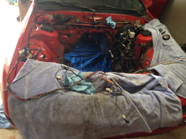
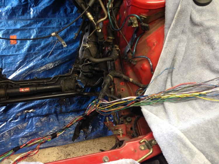
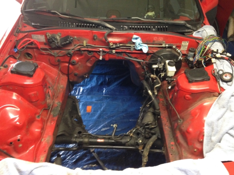
I brought the Front Harness wires into the car and separated them. I cut the unused wires near the loom and wrapped them. I'll bolt them onto the footwell before putting the dash back on. I'll need to recheck all the connections going to the engine bay later before I route the harness under the front wheel well.
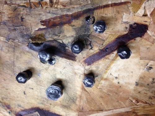
Then I removed the steering rack. I made two mistakes; not too detrimental. I tried to unbolt the steering rack clamps from the top side. Unfortunately the nuts on the top were attached to the clamps and I realized that after breaking one off with my impact gun. I can easily have the local welding shop weld these back on and I'll also have them reinforce the other nuts as well. Then when I was removing the outer tie rods, I ended up banging them with a hammer to push them out since I didn't have a ball joint puller. This destroyed the threads. Again not a huge problem since I'll just replace them. Unfortunately both of the joints were in pretty good shape, though one dust cover was torn. Thanks to the forum members, these are sold on Amazon as "Raybestos 401-1572" in case anyone else makes the same mistake.
Then I was unable to get the inner tie rods off for the life of me. I read the FSM to make sure they are not left hand threads, which they are not. I made sure there is no lock pin in them, which there isn't. But still I could not get them off. I took them to my local mechanic to have them give it a shot.
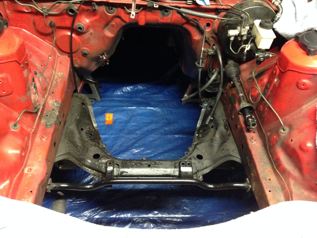
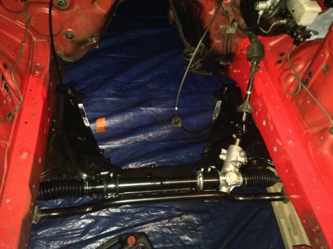
Here is what the bay looks like now:
Then I removed the steering rack. I made two mistakes; not too detrimental. I tried to unbolt the steering rack clamps from the top side. Unfortunately the nuts on the top were attached to the clamps and I realized that after breaking one off with my impact gun. I can easily have the local welding shop weld these back on and I'll also have them reinforce the other nuts as well. Then when I was removing the outer tie rods, I ended up banging them with a hammer to push them out since I didn't have a ball joint puller. This destroyed the threads. Again not a huge problem since I'll just replace them. Unfortunately both of the joints were in pretty good shape, though one dust cover was torn. Thanks to the forum members, these are sold on Amazon as "Raybestos 401-1572" in case anyone else makes the same mistake.
Then I was unable to get the inner tie rods off for the life of me. I read the FSM to make sure they are not left hand threads, which they are not. I made sure there is no lock pin in them, which there isn't. But still I could not get them off. I took them to my local mechanic to have them give it a shot.
Here is what the bay looks like now:
 05-03-15, 10:00 PM
#62
Full Member
Thread Starter
iTrader: (3)
Join Date: Mar 2013
Location: Minnesota
Posts: 54
Likes: 0
Received 0 Likes
on
0 Posts
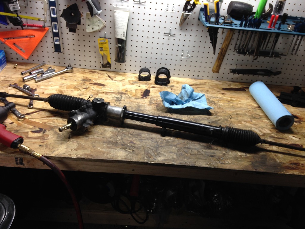
De-Powering the Steering Rack
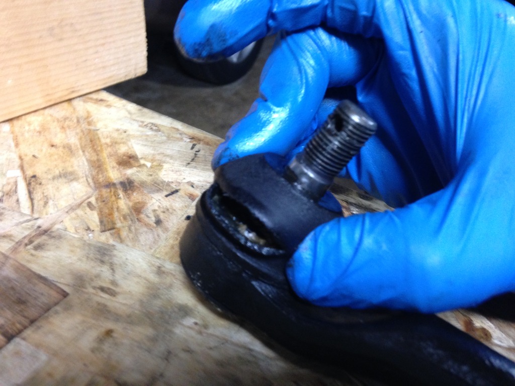
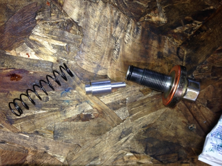
After taking the steering rack off the car and removing all the lines, I started taking it apart and laying it out. You can see the new tie rod ends I had to buy since I ruined the threads by bashing on the old ones.
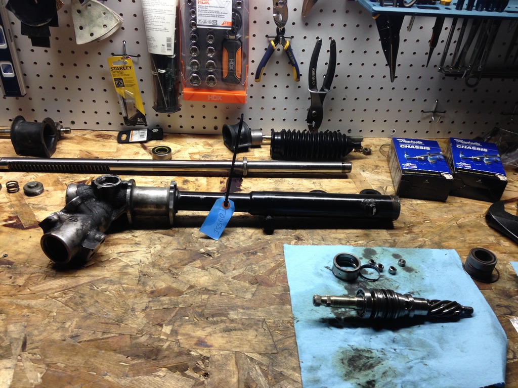
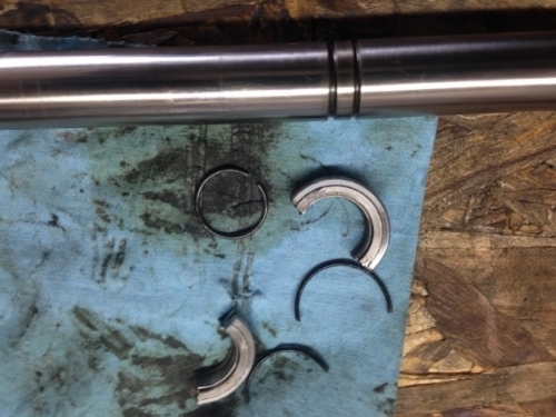
I had to get the bearing off in order to remove the center part of the pinion shaft.
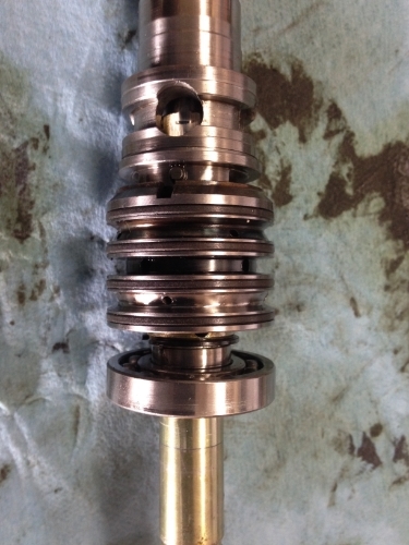
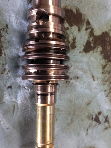
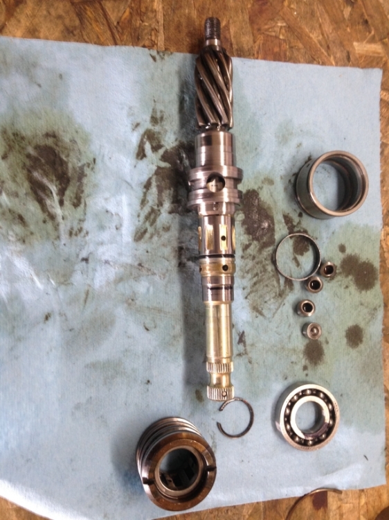
Then the enemy seal was destroyed.
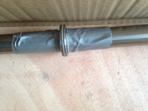
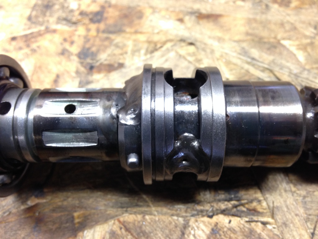
Then I had the local weld shop weld the pinion shaft to fix the inherent play. I also had them reinforce the nuts on the brackets that I broke earlier with my impact gun and also spot weld the hose end bolts.
Then I reassembled the steering rack and used lots of grease. I also painted the brackets and the rack with black spray paint. I still need to finish the engine bay before the rack can go back in.
I had to get the bearing off in order to remove the center part of the pinion shaft.
Then the enemy seal was destroyed.
Then I had the local weld shop weld the pinion shaft to fix the inherent play. I also had them reinforce the nuts on the brackets that I broke earlier with my impact gun and also spot weld the hose end bolts.
Then I reassembled the steering rack and used lots of grease. I also painted the brackets and the rack with black spray paint. I still need to finish the engine bay before the rack can go back in.
Last edited by Thepersian; 05-03-15 at 10:04 PM.
05-04-15, 06:44 PM
#63
Rotary Enthusiast
iTrader: (1)
Join Date: Nov 2012
Location: bloomington, mn
Posts: 1,100
Likes: 0
Received 0 Likes
on
0 Posts
you are now my guinea pig. I have been contemplating a proper PS delete like this. I am still trying to locate my slop before I commit though. Nice work as usual!
05-06-15, 08:26 AM
#64
Full Member
Thread Starter
iTrader: (3)
Join Date: Mar 2013
Location: Minnesota
Posts: 54
Likes: 0
Received 0 Likes
on
0 Posts
It was certainly a learning process and I now know how to do things a bit more efficiently next time. Have you checked the inner tie rods as the cause of your slop?
05-06-15, 05:40 PM
#65
Rotary Enthusiast
iTrader: (1)
Join Date: Nov 2012
Location: bloomington, mn
Posts: 1,100
Likes: 0
Received 0 Likes
on
0 Posts
But enough about my problems lol.
05-18-15, 09:38 PM
#66
Full Member
Thread Starter
iTrader: (3)
Join Date: Mar 2013
Location: Minnesota
Posts: 54
Likes: 0
Received 0 Likes
on
0 Posts
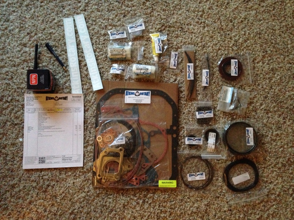
Engine Rebuild
It's been a while since my last update, not because the project has slowed down but I just haven't had a chance to sit behind the computer and update the progress. I finished painting the steering rack brackets, and then the box of goodies arrived from Atkins.
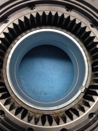
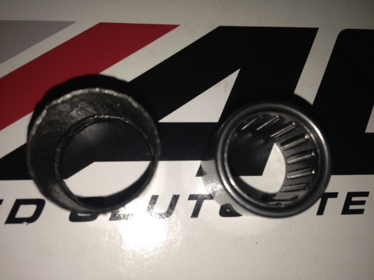
As soon as the weekend hit, I started working on the rebuild. First thing was to replace the stationary gear and rotor bearings with brand new OEM ones. You can see the comparison of the old and new. Even though the old is still within spec (<20% copper exposed), since I had the engine opened I decided that it was a cheap enough and important part of the rebuild.
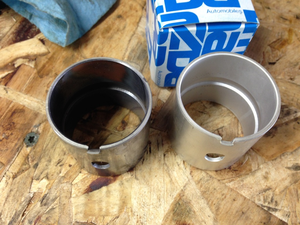
The initial loud bang with the first press out of the bearing scared the $#!& out of me. But it was all smooth after that. Alignment was no issue with any of the bearings. The key is to get them pressed in a little by hand making sure they are parallel with the lip in 2 different directions 90 degrees apart. I used a line to help me align the tabs with the key in the rotors. I first started with the stationary gears.
Then onto the rotors.
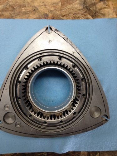
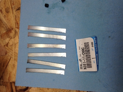
Then I laid out all of the pieces to make sure they were all there. Using the FSM, Aaron's rebuild video and Hayne's manual I started to slowly put the pieces together. First off was of course the rotors and all their pieces starting with side seal clearance. Like I mentioned before I used all new parts to rebuild the engine; including OEM apex seals, side seals and corner seals with the FD corner springs.
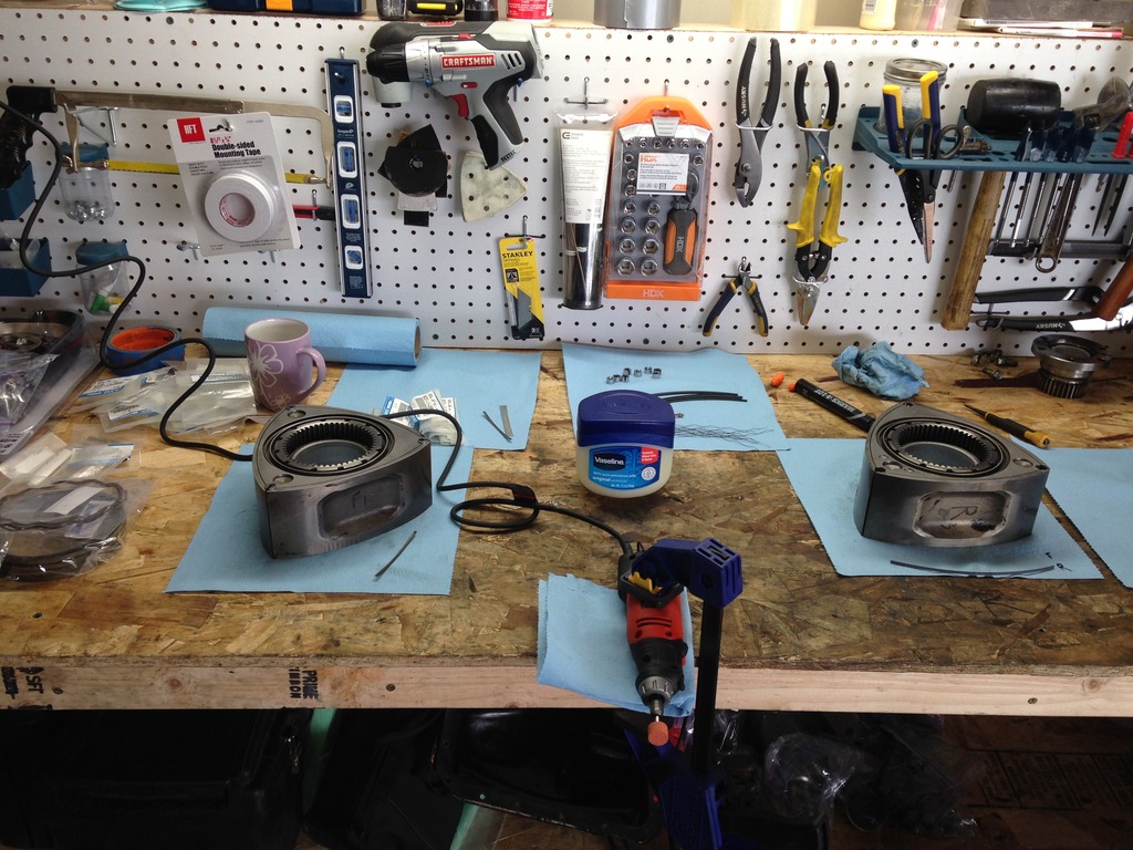
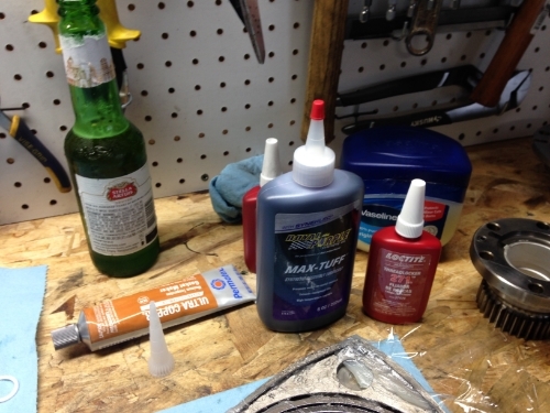
I finished putting the short block together with the help of my friend Eric; who made it a lot more fun. It took us about 7-8 hours from the start to torquing down the tension bolts. We took it slow, checked and rechecked every step to avoid any mistakes. We did have to take things apart halfway to ensure the triangular part of the apex seals in the front rotor were facing the rear of the engine (1 wasn't; not sure if it makes that much of a difference but that's what the FSM says).
As soon as the weekend hit, I started working on the rebuild. First thing was to replace the stationary gear and rotor bearings with brand new OEM ones. You can see the comparison of the old and new. Even though the old is still within spec (<20% copper exposed), since I had the engine opened I decided that it was a cheap enough and important part of the rebuild.
The initial loud bang with the first press out of the bearing scared the $#!& out of me. But it was all smooth after that. Alignment was no issue with any of the bearings. The key is to get them pressed in a little by hand making sure they are parallel with the lip in 2 different directions 90 degrees apart. I used a line to help me align the tabs with the key in the rotors. I first started with the stationary gears.
Then onto the rotors.
Then I laid out all of the pieces to make sure they were all there. Using the FSM, Aaron's rebuild video and Hayne's manual I started to slowly put the pieces together. First off was of course the rotors and all their pieces starting with side seal clearance. Like I mentioned before I used all new parts to rebuild the engine; including OEM apex seals, side seals and corner seals with the FD corner springs.
I finished putting the short block together with the help of my friend Eric; who made it a lot more fun. It took us about 7-8 hours from the start to torquing down the tension bolts. We took it slow, checked and rechecked every step to avoid any mistakes. We did have to take things apart halfway to ensure the triangular part of the apex seals in the front rotor were facing the rear of the engine (1 wasn't; not sure if it makes that much of a difference but that's what the FSM says).
05-18-15, 10:10 PM
#67
Full Member
Thread Starter
iTrader: (3)
Join Date: Mar 2013
Location: Minnesota
Posts: 54
Likes: 0
Received 0 Likes
on
0 Posts
Engine Rebuild cont'd
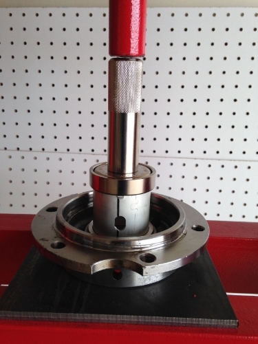
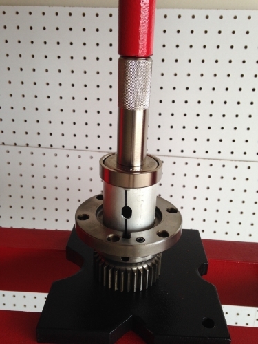
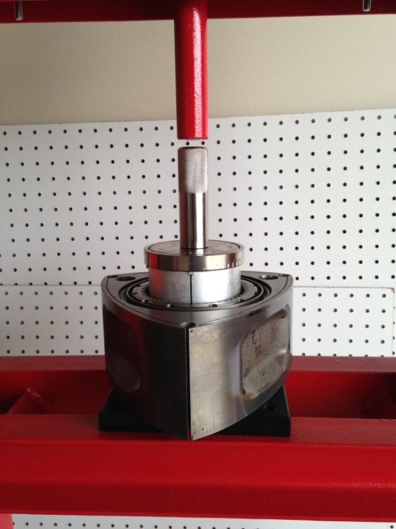
Then the next day, I put the front cover pieces together; again taking extra care to not wedge the Torrington bearing under the spacer. I used the new Torrington bearings that came in the Atkins kit. I assembled the pieces in mock up to check the end play.
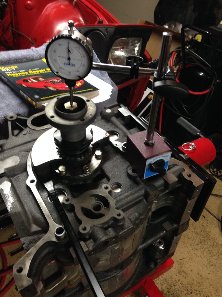
First I used the "Y" spacer; which the engine was originally built with. I guess this engine was in the rare group that doesn't use the "V" spacer. With the "Y" spacer, there was absolutely no end play. So then I moved up to the "K" spacer. The clearance needs to be 0.0016 to 0.0028" according to the FSM.
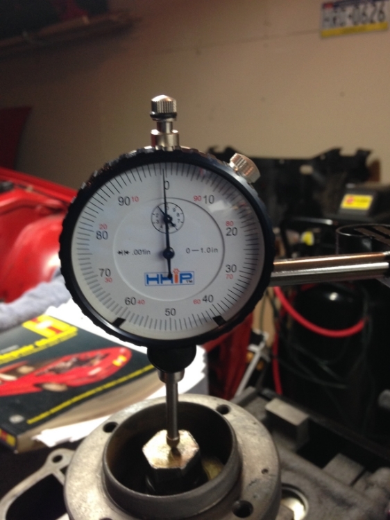
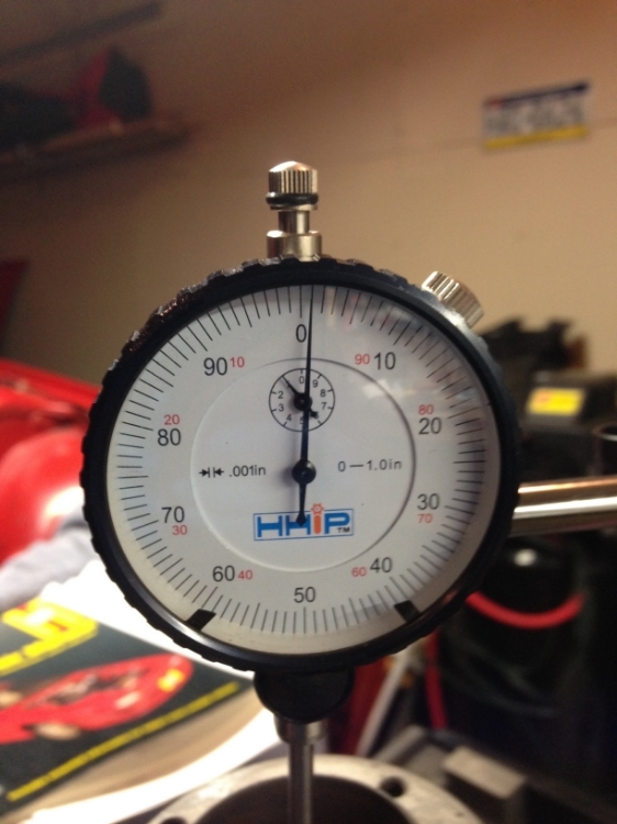
With the "K" spacer, as you can see it sits just below 0.0015" which is too tight. I was surprised by this and rechecked everything again but still was too tight. I ordered the next one on the list, an "X" spacer from Atkins.
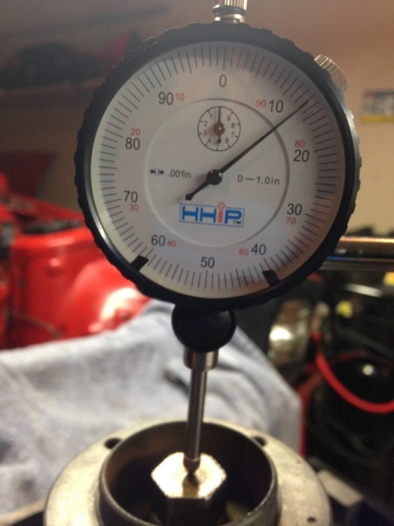
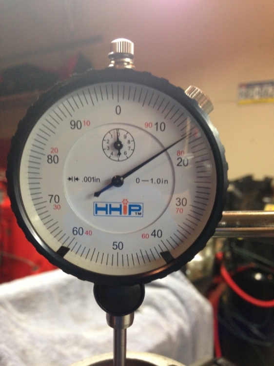
Right about 0.0025" with the "X" spacer. PERFECT!!!
Then I reassembled all the front cover pieces. Sliding on the oil pump gear ring without knocking the key out was a pain in the a$$. I used a bypass for the eccentric shaft front bolt oil thermostat and torqued down the front bolt.
Then I flipped the engine over and installed the rear oil pressure regulator and front oil pressure valve. I modified the rear by pressing in the end to increase oil pressure and shimmed the front pressure valve with 2 washers.
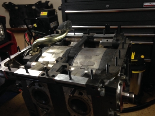
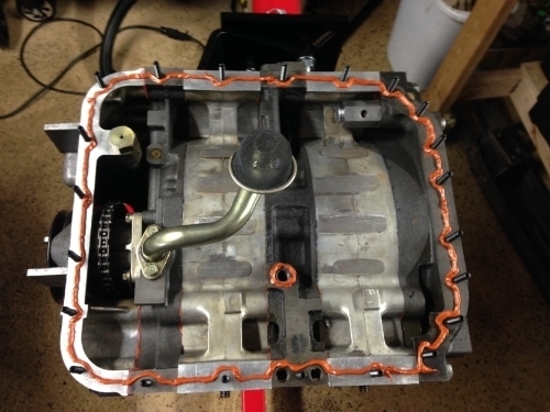
Then I started working on the oil pan. I decided to forgo using an oil pan gasket based on what I have read on the forums. I used the Banzai racing oil pan brace, since I had heard good things about it.
First I used the "Y" spacer; which the engine was originally built with. I guess this engine was in the rare group that doesn't use the "V" spacer. With the "Y" spacer, there was absolutely no end play. So then I moved up to the "K" spacer. The clearance needs to be 0.0016 to 0.0028" according to the FSM.
With the "K" spacer, as you can see it sits just below 0.0015" which is too tight. I was surprised by this and rechecked everything again but still was too tight. I ordered the next one on the list, an "X" spacer from Atkins.
Right about 0.0025" with the "X" spacer. PERFECT!!!
Then I reassembled all the front cover pieces. Sliding on the oil pump gear ring without knocking the key out was a pain in the a$$. I used a bypass for the eccentric shaft front bolt oil thermostat and torqued down the front bolt.
Then I flipped the engine over and installed the rear oil pressure regulator and front oil pressure valve. I modified the rear by pressing in the end to increase oil pressure and shimmed the front pressure valve with 2 washers.
Then I started working on the oil pan. I decided to forgo using an oil pan gasket based on what I have read on the forums. I used the Banzai racing oil pan brace, since I had heard good things about it.
05-22-15, 04:27 PM
#70
Full Member
Thread Starter
iTrader: (3)
Join Date: Mar 2013
Location: Minnesota
Posts: 54
Likes: 0
Received 0 Likes
on
0 Posts
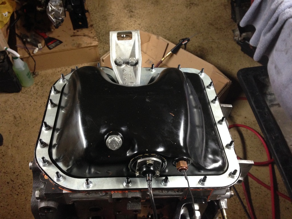
It took a lot of scrubbing and cleaning to get it there. The oil leak + dust and dirt overtime = Difficult to clean. The sensor on the left is the oil level sensor. The one on the right is part of the warm up system. Since that system has been deleted, I'm just using it as a plug.
 quite disheartening isn't it?
06-21-15, 02:36 PM
quite disheartening isn't it?
06-21-15, 02:36 PM
#72
Full Member
Thread Starter
iTrader: (3)
Join Date: Mar 2013
Location: Minnesota
Posts: 54
Likes: 0
Received 0 Likes
on
0 Posts
Miscellaneous updates
Hey everyone. Again, I was very busy with work for the past few weeks. Meanwhile a few new parts have arrived and some repairs/reassembly has been done. Here it goes.
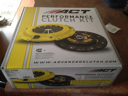
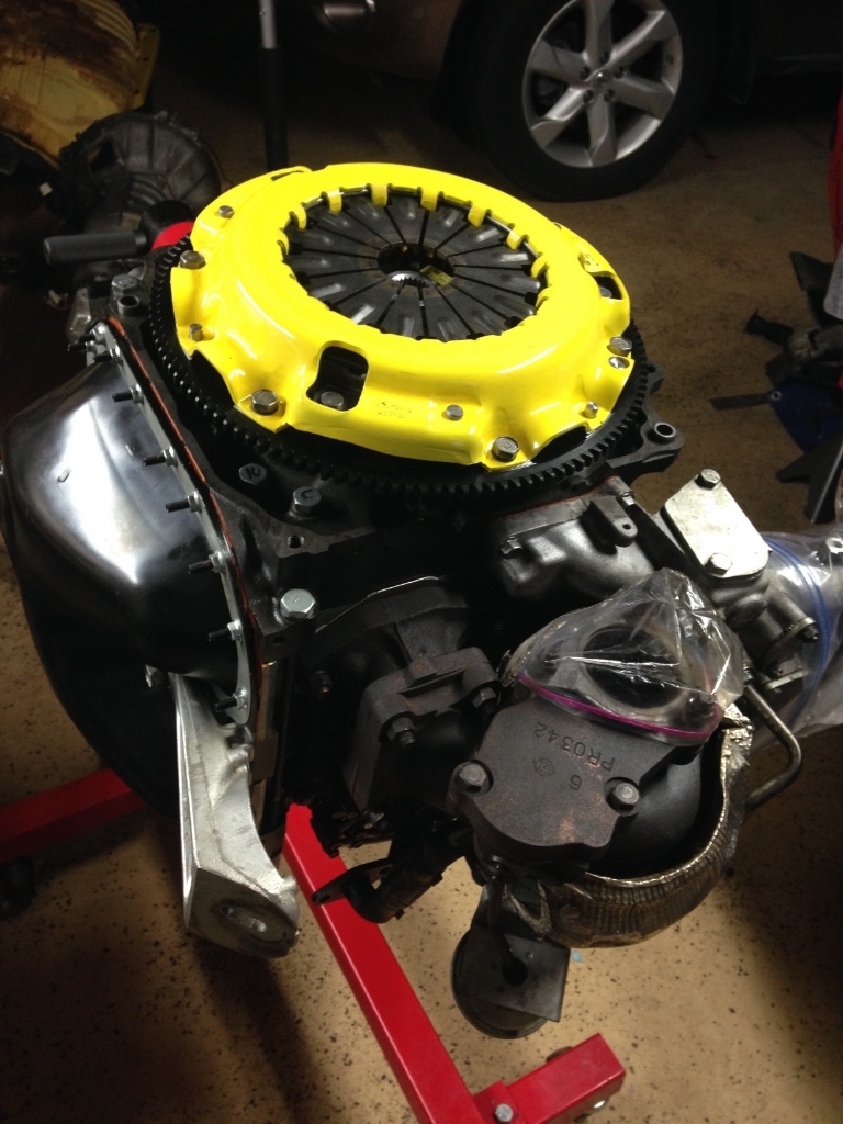
First of all, some goodies arrived in the mail. Lightened steel flywheel, rear counterweight, and Performance street disc/Extreme pressure plate combo. All are from ACT. I think for my price range they make the best quality products. The clutch combo can support up to 450 ft/lb of torque, plenty for my build. I went with the steel as opposed to aluminum flywheel to balance torque delivery and idling capability.
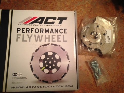
I didn't wait long before I put this beauty on the freshly rebuilt engine. Something to note, I didn't have a torque wrench capable of 300 ft/lbs. I used a technique described by Aaron Cake, which is to torque down the E-shaft nut until 150 ft/lbs and then use an impact gun to tighten an extra 60 degrees. I definitely used a small amount of red loctite as well.
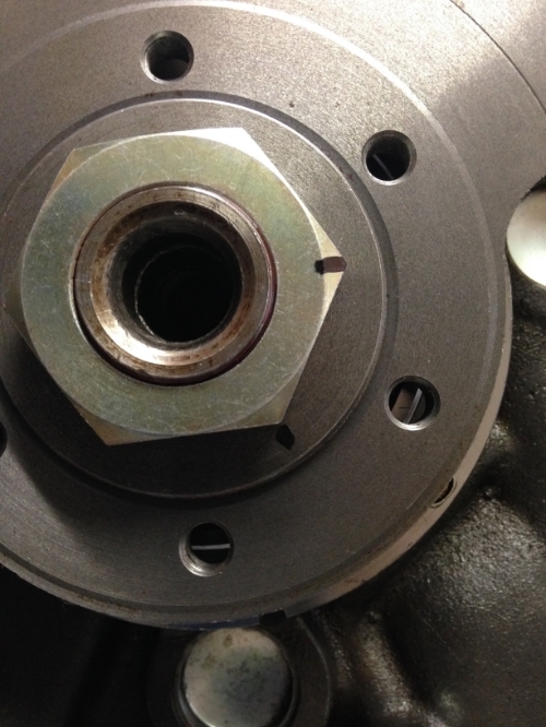
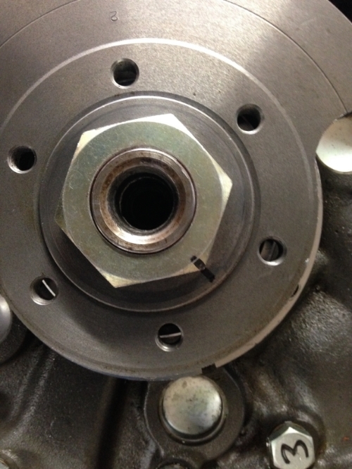
I replaced the pilot bearing. I used the "Blind hole" removal tool from Advance Autoparts which made the job really easy. You can see the previous pilot bearing was severely worn down.
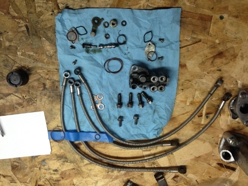
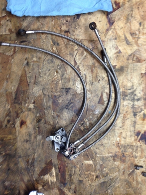
I rebuild the OMP using a write-up from a forum member who sells a Viton O-ring rebuild kit. It was very well written, easy to do and all the parts fit perfectly. Hopefully, this prevents any future leaks from the OMP. All crush washers were replaced with new ones. Old lines were replaced with Stainless Steel lines.
Here is the rest of the assembly. I used a small amount of blue loctite on all bolts for extra insurance. I also reassembled the majority of the "long block" including LIM, turbo and exhaust manifold and the water pump.
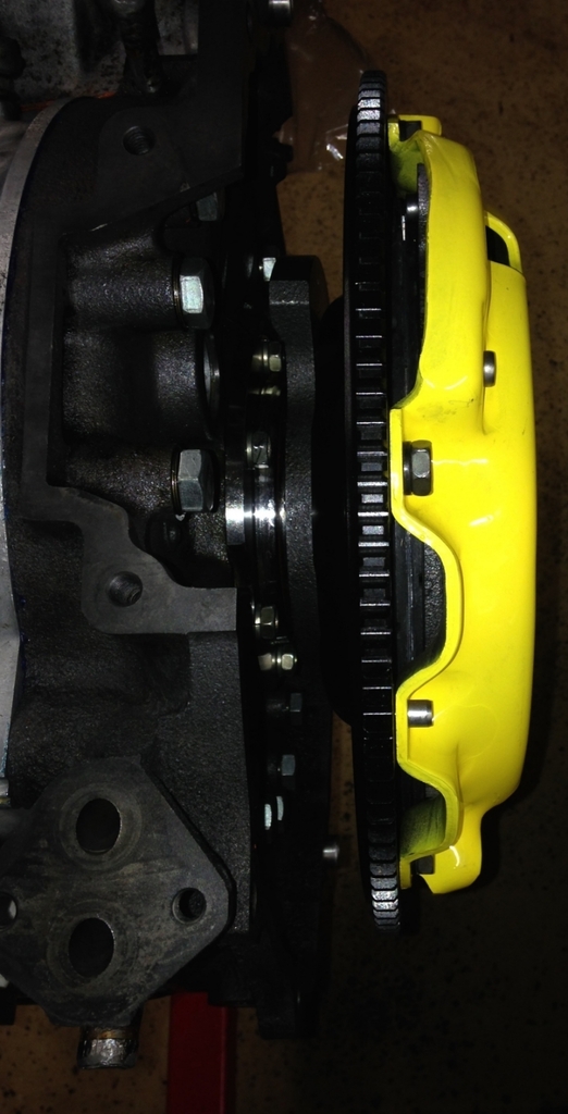
First of all, some goodies arrived in the mail. Lightened steel flywheel, rear counterweight, and Performance street disc/Extreme pressure plate combo. All are from ACT. I think for my price range they make the best quality products. The clutch combo can support up to 450 ft/lb of torque, plenty for my build. I went with the steel as opposed to aluminum flywheel to balance torque delivery and idling capability.
I didn't wait long before I put this beauty on the freshly rebuilt engine. Something to note, I didn't have a torque wrench capable of 300 ft/lbs. I used a technique described by Aaron Cake, which is to torque down the E-shaft nut until 150 ft/lbs and then use an impact gun to tighten an extra 60 degrees. I definitely used a small amount of red loctite as well.
I replaced the pilot bearing. I used the "Blind hole" removal tool from Advance Autoparts which made the job really easy. You can see the previous pilot bearing was severely worn down.
I rebuild the OMP using a write-up from a forum member who sells a Viton O-ring rebuild kit. It was very well written, easy to do and all the parts fit perfectly. Hopefully, this prevents any future leaks from the OMP. All crush washers were replaced with new ones. Old lines were replaced with Stainless Steel lines.
Here is the rest of the assembly. I used a small amount of blue loctite on all bolts for extra insurance. I also reassembled the majority of the "long block" including LIM, turbo and exhaust manifold and the water pump.
Last edited by Thepersian; 06-22-15 at 09:04 AM.
06-29-15, 08:35 PM
#74
Full Member
Thread Starter
iTrader: (3)
Join Date: Mar 2013
Location: Minnesota
Posts: 54
Likes: 0
Received 0 Likes
on
0 Posts
More Misc Updates
 . Based on my research I'm pretty confident it will work but next time I'll definitely take you up on your offer.
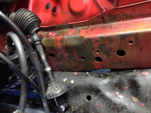
 When I tore down the engine bay, there was a large area in the chassis that the paint had chipped off and it was starting to show evidence of rust. I decided to clean it up with a wire wheel on a dremel and paint it to prevent any deeper rust damage. This is just for good measures and I may end up getting the bay sanded and repainted down the road. There was also a small area on the subframe that needed the same TLC. I sprayed 4 coats of paint to make sure that it lasts for some time.
Before:
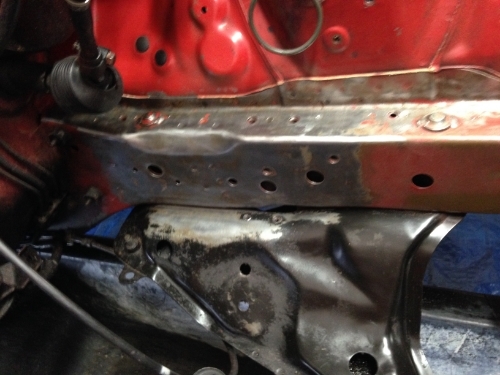
After cleaning with the wire wheel:
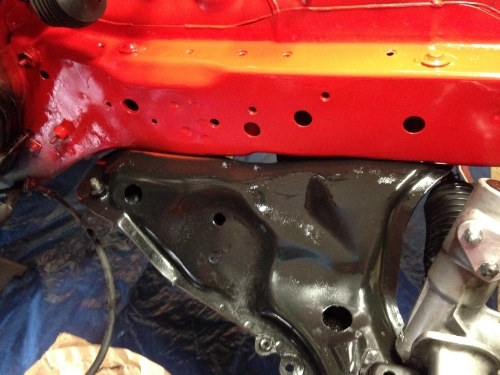
Finally:
The De-powered steering rack also went in the car with brand new outer tie rods. I love the grease fittings in the outer tie-rods.
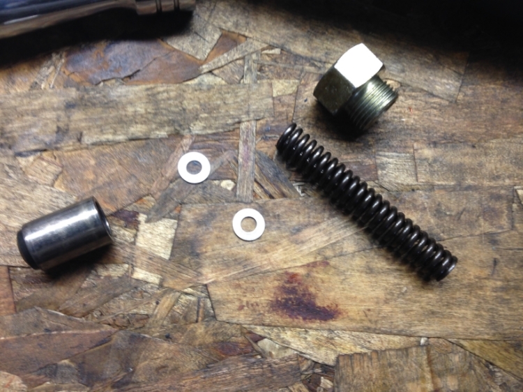
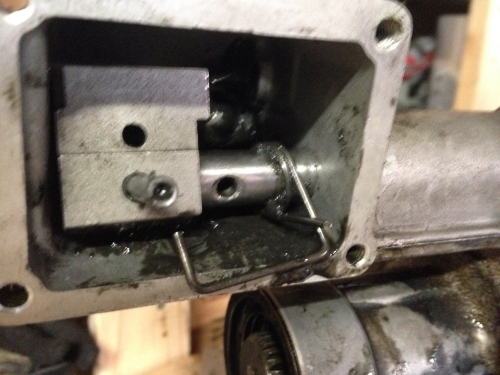
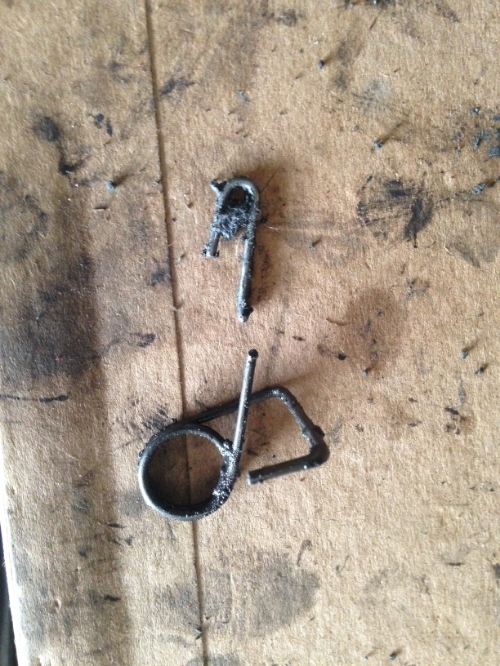
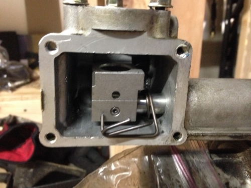
When I first bought the car, the shifter wouldn't return to center from the left side (1st and 2nd gear side). The centering spring was broken; which is apparently a well known issue with these cars. Here are some pictures of the repair. It worked beautifully after I replaced it. I can't believe some people do this with the transmission in the car. It was a PITA to do out of the car!
Broken spring:
Replaced:
It may be a while before the next update. You can bet it's going to be a big one. I'm planning on cleaning the transmission, and putting the transmission with the engine back in the car. Work is getting busy as usual and I have to find a pressure washer to give the transmission a nice scrub then. After that I'll be trying to pick up some extra shifts to fund the fuel injectors and EMS with all of the necessary wiring accessories.
06-30-15, 08:46 AM
#75
Rotary Enthusiast
iTrader: (1)
Join Date: Nov 2012
Location: bloomington, mn
Posts: 1,100
Likes: 0
Received 0 Likes
on
0 Posts
I had paint wear in that exact same spot. I chalk it up to people spilling fluids in the area. Looking good though. Let me know if you ever need a hand.