When you click on links to various merchants on this site and make a purchase, this can result in this site earning a commission. Affiliate programs and affiliations include, but are not limited to, the eBay Partner Network.
So after a ten year restoration (read about that here) and then a seven week rush to get ready for DGRR (read about that one here), it is now time for what is hopefully the closing part of what is now a trilogy. At the end of the seven week scramble, I discovered the engine had a blown coolant seal. So, that left me with a few options. Have someone else do the work, do the work myself, or sell it. Selling it was never truly an option, but my wife did say if I sold it, I could buy a brand new ND. Tempting, but I passed. And given that I've done everything else myself up to this point, I decided to go all in and go for it myself yet again.
First I acquired an engine stand and a hoist:
And then, on engine removal day, I forgot to take a single picture. Not one. Nothing. My friend came over to help and we threw ourselves into it and were very busy. We had quite a few hiccups but made lots of progress. However, the engine never even came out that day. I should have done some more reading on the forum, as other people have mentioned it. The lesson to be learned is do not pull an RX-7 engine with the 1 ton Harbor Freight hoist. The problem surely isn't weight, it's boom length. You could do it with the 1 ton, and people have, but it did not seem to be the smoothest of setups. So, Harbor Freight was gracious enough to take back the 1 ton and let me exchange it for the 2 ton at no penalty to me. And then, we were really ready to go.
My friend came back over and within minutes, the engine was out.
Yo Jerry,
Glad to see you tackling this yourself. I�m sure the end result will be highly rewarding. I�ll be along for the ride and in for updates and any tips I can pick up.
Yo Jerry,
Glad to see you tackling this yourself. I�m sure the end result will be highly rewarding. I�ll be along for the ride and in for updates and any tips I can pick up.
Great to hear from you again! I've got some plans for this part that will hopefully achieve my vision of a very clean, great looking engine bay.
I guess to stick with a timeline, the engine was prepped for removal on 6/12/2021, and finally came out on 6/17/2021.
And then came engine tear down weekend, 6/19-6/20/2021. The first day, I stripped the engine of all accessories.
It turns out I didn't take very many pictures that day either, because before you know it, I was here:
One keg, ready for tear down the next day. And I had a strong hunch which rotor had failed:
You got this Jerry, I did mine last fall and I actually really enjoyed the process.
How easy is it to get housings now with the shipping issues going on?
thanks for the doing this build thread.
Uh, not easy! But they are on the way (at least the front, intermediate, and rear are). Based on the ETA, it's all off the coast, just waiting to be unloaded. I drug my feet on ordering stuff and still haven't ordered everything (need rotor housings and a few other ancillary parts). Thankfully, other than DGRR, I don't think I've missed too many events that I would have really liked to go to.
I've devoted a lot of time to the rebuilding of the emission harness, and I am now at the point where I have completely deconstructed my old one and am ready to begin building the new one.
I've neglected to update this thread, but that's because nothing really has happened. I focused on the new wiring harness, which I dedicated a separate thread to. The harness is essentially done (update on that coming soon, too) and now it's time once again to play catch up. The engine build and some associated mods coming up in February. I'd like to have an engine in and running by mid March so I have it broken in before Deals Gap Rotary Rally.
Nice choice in biting the bullet and springing for all new housings. Planning to leak check the keg?
Hit me up if you're considering your clutch options (like light flywheel )
Last edited by cone_crushr; Feb 1, 2022 at 11:09 PM.
OOOOH, virgin plates & housings, sweet! Are you going to do any porting on them? If you want to stick with the stock ECU, which I suspect you do since you're building a new OEM harness, I'd recommend skipping the porting, and if you do port, don't get too aggressive with it. Reason being is a big aggressive street port that significantly alters port timing & overlap will be difficult for the stock ECU to deal with, and you probably won't be happy with idle quality and light throttle/low RPM performance.
When I built mine, the used but like new plates & housings I got for my build came with a pretty aggressive street port, and my idle ended up being lumpy & low RPM performance sucked on an Rtek 2.x modified stock ECU. As much as I tried, the Rtek lacked enough tune-ability to deal with the ports, so I ended up expanding the project and went all out with an aftermarket ECU and a bunch of supporting fuel/ignition mods. It runs great now, and makes a pretty impressive 360~380RWHP at 15psi boost.
Nice choice in biting the bullet and springing for all new housings. Planing to leak check the keg?
Hit me up if you're considering your clutch options (like light flywheel )
Yes, I'll be leak checking the keg once built and before I bolt on any accessories. Didn't know I should have hit you up for some options. I'm going Exedy lightweight steel flywheel and Exedy stock clutch/pressure plate.
OOOOH, virgin plates & housings, sweet! Are you going to do any porting on them? If you want to stick with the stock ECU, which I suspect you do since you're building a new OEM harness, I'd recommend skipping the porting, and if you do port, don't get too aggressive with it. Reason being is a big aggressive street port that significantly alters port timing & overlap will be difficult for the stock ECU to deal with, and you probably won't be happy with idle quality and light throttle/low RPM performance.
You've guessed correctly, Pete. OEM harness and staying with stock ports. This build is going to be fairly OEM in virtually all aspects. We'll see if I ever get wild someday, but a nice new engine I can enjoy for a long time is something looking forward to.
Yes, I'll be leak checking the keg once built and before I bolt on any accessories. Didn't know I should have hit you up for some options. I'm going Exedy lightweight steel flywheel and Exedy stock clutch/pressure plate.
Exedy light flywheel and cluch are another good choice. I see you favor keeping it stock, but a light flywheel on a TII is a good mod. I'd consider upgrading apex seals too, although Mazda will work OK.
Last edited by cone_crushr; Feb 2, 2022 at 01:31 PM.
Just finished reading the original resto thread and can't believe it's still going! I just got an 86 GXL and this definitely gives hope for the full restoration goal. Anyway, I was curious if you were going to go for the OMP delete and get the aftermarket premix pump or just go for OEM?
First up is my gauge situation. I do not want aftermarket gauges cluttering up the interior. My first RX-7 I put a DIN gauge panel in when I had an aftermarket stereo. This was the best solution at the time, but I hated the duplicative nature of having two water temp and oil pressure gauges. There's lots of really cool routes you could take this - replace the stock cluster with all aftermarket stuff for one. However, that's a tight fit to get four 52mm gauges in there plus a tach and speedo. I'm not putting anything on my brand new OEM a-pillar trim. After a lot of thought, I decided I had to be able to monitor water temp, oil temp, and oil pressure better than the stock gauges (or at all for oil temp). That led me to these gauges:
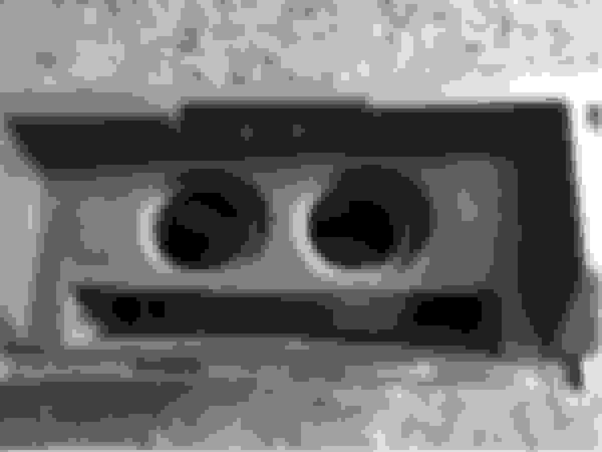
Glow Shift digital gauges. One dedicated to water temp, the other a dual temp/pressure gauge for oil. Now where to mount them without cluttering the interior so I can have 100% OEM look? I'm not going to stare at them, just want to be able to look every now and then. That led me to what I think is a decent spot - the glove box. So, let's get these mounted.
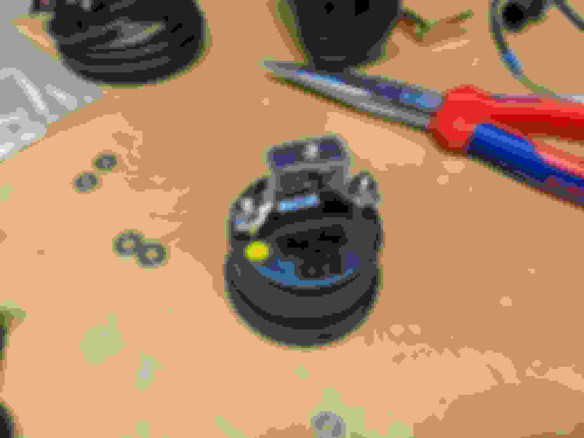
The water temp gauge has only a six pin harness with only five pins used. The oil temp/pressure gauge has three connectors, one for gauge power functions, and one each for the sensors.
Glow Shift has some universal pods on their website, which is what I used. Added the posts needed for the mounting bracket and the bracket, and I was off and running.
Then came time to do something terrible, just downright awful - drilling holes in my mint glove box and mounting the gauges.
Next up, wiring. This is pretty straightforward. Each gauge needs 12V+ constant (for memory function of keeping the color you select), 12V+ switched, ground, and optional 12V+ headlight for a dimming feature. The temp sensors have two leads signal and ground, and the oil pressure has three, signal, ground, and what I assume is positive voltage for power. Added some expandable sleeving for looks, even though virtually none of it is visible anywhere.
Now came brainstorming time and where do I want to get constant power, switched power, and a ground from with the least amount of destruction? A glance at the wiring diagram and I quickly knew where:
I don't need to cut into anything. During my restoration, I removed ABS, partly because I wanted to, but mostly because I forgot to put the trigger wheels on the rear hubs and didn't want to destroy a set of rear wheel bearings. There's a 4 pin .250 connector down where the ABS computer used to live. And it has a ground, 12V+ constant from the battery via the BTN and ABS fuses, and 12V+ switched power from the sunroof fuse. Perfect. I made a harness for it. I also made a connector for all of the sensor wires which I had already incorporated into my new OEM style emissions harness I am making.
Some time spent at the workbench, and I produced this finished glovebox, ready for reinstallation:
The nine position connector incorporates a common ground, 12V+ headlight, 12V+ switched, and 12V+ constant and wires for the sensor signals, pressure sensor power, and a common sensor ground that branches out back in my emission harness. I still need to finish the sub-harness that will run from the ABS connector on the front harness and the five position I put on the emission harness to the nine position at the glove box. However, I couldn't resist hooking up to a power supply and at least turning on the gauges:
I believe the water temp gauge was set to amber, and the pressure/temp gauge was set to orange. They are ten color selectable backlit. I also turned off the garage light and while perfectly visible in direct light, did not think they were overbearingly bright in the dark. As such, while I have the provision for it should I choose to add it later, I'm not going to bother tapping into a 12V+ headlight source right now. If anything, I'll have a nice glove box halo if the light manages to peek out at night.
Last edited by JerryLH3; Feb 18, 2022 at 03:59 PM.
I will use the stock OMP with the adapter so that it pushes out premix from a reservoir to the oil injectors.
I've have that same setup on my S5T2 and my FD, and I absolutely love it! Besides finding space for the premix tank, there's one little catch you'll need to deal with - on the S5T2, the stock oil return pipe from the turbo won't clear the RA OMP adapter & OMP assembly once it's installed, because it sticks out a bit further. So you'll need to fab up your own oil drain line. Not all that hard to do, just need a -10AN flange at the turbo & front cover ends, and some -10AN lines & fittings to plumb it up.
As for the oil tank, US Plastics makes tanks with caps in various sizes that have a molded-in 1/4" barb fitting on the bottom, and molded in mounting tabs on one side of the tank. IIRC, they call them "handy tanks" and they are chemically compatible with most chemicals & lubricants, and they are translucent (like the coolant overflow tanks), so you can easily see the fill level at a glance. As for tank location, if you don't have an air pump, that would be the best & easiest location for it - simple bracket using a couple of air pump mounting points.
i have my gauges where the radio was, and its kind of neat but i think they will eventually migrate to the glove box too.
the glovebox is a really common spot actually, HKS used to have something for that (RHD specific, so it would point the wrong way)
food for thought, not sure where the registration goes if you have this, lol
I've have that same setup on my S5T2 and my FD, and I absolutely love it! Besides finding space for the premix tank, there's one little catch you'll need to deal with - on the S5T2, the stock oil return pipe from the turbo won't clear the RA OMP adapter & OMP assembly once it's installed, because it sticks out a bit further. So you'll need to fab up your own oil drain line. Not all that hard to do, just need a -10AN flange at the turbo & front cover ends, and some -10AN lines & fittings to plumb it up.
As for the oil tank, US Plastics makes tanks with caps in various sizes that have a molded-in 1/4" barb fitting on the bottom, and molded in mounting tabs on one side of the tank. IIRC, they call them "handy tanks" and they are chemically compatible with most chemicals & lubricants, and they are translucent (like the coolant overflow tanks), so you can easily see the fill level at a glance. As for tank location, if you don't have an air pump, that would be the best & easiest location for it - simple bracket using a couple of air pump mounting points.
I already have a -10 flange for the front cover, just need to get one for the turbo. I discovered this was an issue when I attempted to install this back when I did the cooling system. I may make my own oil cooler lines at the same time. Or I may not, mission creep stinks.
I think I have that exact tank already, picked mine up with some line from Aircraft Spruce. Air pump is still in the car, so I think it's going to go where the battery was. I'd like to fit it where the ABS pump was, but I think the brake line gets in the way.


 )
)