4-Rotor FC Build


 12-18-12, 10:28 AM
#1153

Did you cut those holes in the control arms to save wight? I dont get what you mean about the bearings how will they will be benificial? Couldnt you just cut out a piece of derlin and drill a hole in it and just make a solid bushing? Im still learning about the rear suspension so it might be a stupid question but still thought id ask cuase of all people you would know...
12-18-12, 05:40 PM
#1156
I know About those but I was referring to the use of the stock ends...
those aftermarket ends are high maintenance and noisy..
I will never put anything like those on my car again..
Squeak squeak squeak, the swaybar end links I used like that is all they did, it was obnoxious. The stock ends are awesome.
Keep up the good work John you never seize to amaze me
those aftermarket ends are high maintenance and noisy..
I will never put anything like those on my car again..
Squeak squeak squeak, the swaybar end links I used like that is all they did, it was obnoxious. The stock ends are awesome.
Keep up the good work John you never seize to amaze me

@killingtime33:
Sounds like you don't know ferdi (furb) very well
 , anyway let's keep this thread awesome!
Update
Started machining some independend camber adjusters which I'm planning to use to adjust the rear camber of the car. They are a somewhat similar design as the AWR pieces, but I don't like the bronze bushings they use, so I used spherical bearings instead, like the oem ones do. This is needed because the trailing arms rotate around multiple axes. Space is tight so I used a very small bearing, still has a decent load rating though so should be ok. I also used high tensile steel for the blocks and ordered 12.9 grade fine pitch hardware to mount everything, so it should be strong enough when done.
These are the blocks, 2 are used on each side, one with a threaded hole and one with a normal hole. A special bolt with a few nuts will connect the 2 blocks together and allow adjustment. The left block shows the bearing in place, the block next to it shows the bearing locked in there by a spacer ring and a locking clip, all bearings will be locked like this

 12-18-12, 06:12 PM
#1157
 12-18-12, 11:26 PM
#1160
Zoom-ing Goon.
Join Date: Oct 2003
Location: Cape Cod, MA
Posts: 262
Likes: 0
Received 0 Likes
on
0 Posts
12-19-12, 12:03 AM
#1161
They are normal radial spherical plain bearings, just like the ones I used for the front camber plates, front control arms and rear trailing arms. Only difference is that they lack the lubricating groove and holes but that's because of the small size. The ones I use are made my SKF, they have a smaller outside diameter than usual. The SKF designation is GE 8 E, they use an 8mm shaft, which is smaller than the stock 10mm, which is why I'm using high grade mounting hardware.
12-19-12, 02:00 PM
#1162
They are normal radial spherical plain bearings, just like the ones I used for the front camber plates, front control arms and rear trailing arms. Only difference is that they lack the lubricating groove and holes but that's because of the small size. The ones I use are made my SKF, they have a smaller outside diameter than usual. The SKF designation is GE 8 E, they use an 8mm shaft, which is smaller than the stock 10mm, which is why I'm using high grade mounting hardware.
Why didn't you just use a GE 10 E? is the extra 3mm of OD really that big of an issue? I guess when you test fit them I'll see.
also, why didn't you use a GE 8 C instead? (the maintenance free version)
it also looks like yours have some sort of rubber dust boot? or is that just my eyes playing tricks on me.
12-19-12, 05:15 PM
#1163
Yes, the 3mm's of room is an issue, space in the trailing arm is limited. When the blocks are machined thin it might fit, but it's too close for comfort for me. Also using a GE 10 bearing wouldn't make it stronger, the weak point in an independent camber adjuster is not the bearing or the bolt securing that bearing to the subframe or trailing arm. The bolt that's used for adjusting is the weak point. That bolt isn't inline with the mounting points so it sees bending forces. Choosing a bigger spherical bearing greatens the distance between the adjusting bolt and the mounting points making the weakest point weaker. It's just 1,5mm's but it makes a difference. Together with the possible problems of getting it to fit it was enough of a reason for me to go with the smaller bearing.
I wanted to use GE C bearings, but there are pretty expensive, I can get spherical bearings for cheap, because I can get a 75% discount if I order them at work but even with the discount it still was expensive. I ordered most of the needed spherical bearings at once, and had them make up a price for maintenance free versions and normal versions, the maintenance free versions were about 5 times as expensive, so I went with the normal ones and added grease fittings everywhere possible. I'll live with greasing everything up every few trackdays.
And no, there isn't a rubber dustboot. The bearing goes in the middle, 2 steel spacers (one on each side) sit against the bearing, and 2 (again, one on each side) circlips make sure the spacers and bearing can't move. I couldn't place the locking circlips directly against the bearing because it would limit movement of the bearing. I don't have a cad drawing of it, but I'll try to make some more pictures of how everything goes together next time.
12-20-12, 08:57 AM
#1164
rotary!!

Join Date: Nov 2004
Location: The Netherlands
Posts: 145
Likes: 0
Received 0 Likes
on
0 Posts
John, i think i had one of the very few dutch fc's that was factory without powersteering. I can only say i never missed powersteering (besides when parking in a tighed spot ) and the "ride feeling" is tremendous!
12-23-12, 04:39 PM
#1167
Modified the mounts where the subframe attaches to the chassis. The rubber is gone and the entire subframe / diff / suspension now sits a little bit closer to the chassis.
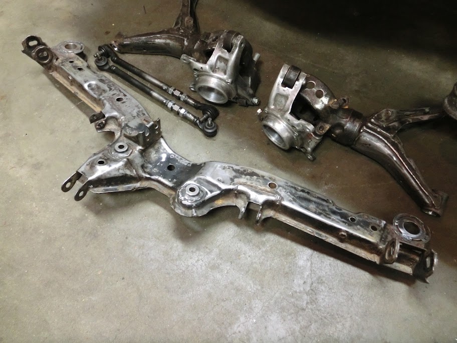
Had to machine more bushings for this. Also with the subframe sitting closer to the chassis the center link bar was too long, so I made a new one. Delrin bushings are used to mount the subframe to the chassis. I'll machine similar delrin bushings for the rear differential mounts. Not sure about the front differential mount yet, but it's probably going to be solid steel.

Had to machine more bushings for this. Also with the subframe sitting closer to the chassis the center link bar was too long, so I made a new one. Delrin bushings are used to mount the subframe to the chassis. I'll machine similar delrin bushings for the rear differential mounts. Not sure about the front differential mount yet, but it's probably going to be solid steel.
 12-27-12, 05:23 PM
#1173

I'm still thinking about what to do with the front diff mount, where it's mounted to the subframe. I heard about people having problems with the rubber flexing too much causing the driveshaft flange to hit the chassis. Maybe I should machine a solid mount, or just weld metal strips to the stock mount to make it solid, or find a way to mount a bumpstop to the chassis so the differential can move around a tiny bit but not hit the chassis, or make something with a delrin sleeve or something
I also messed around with differentials by the way

On the left is a stock S4 TII one, All the S4 TII's I've come across here in the netherlands have an open diff, like you see on the left. It is the bigger differential with larger ring gear, but they don't have the LSD.
Must've been an option or something. I found a seperate LSD unit out of an US S4 TII though, so I bought and disassembled it. Everything looked perfect and measured ok, preload was around 42Nm, so it's not horribly worn out. I did move around some plates though, normally there are 4 friction surfaces in an S4 LSD clutchpack, but by swapping plates around it's possible to get 8 friction surfaces, so I did that and checked preloaded breakaway torque again, which is about 90Nm at the moment. Maybe I'll shim it out a little bit to get 110-115Nm preload and start from there.
12-27-12, 05:34 PM
#1174
To stop the front of the diff flexing upwards and hitting the chassis, I know some people have drilled through the body and put in a pinion snubber/bump-stop thing like you're talking about. Like in this thread: https://www.rx7club.com/forum/showthread.php?t=867300
I'd like to see what you can come up with that's less of a band-aid though!
I'd like to see what you can come up with that's less of a band-aid though!
12-28-12, 01:11 AM
#1175
Rotary Enthusiast
iTrader: (2)
Join Date: May 2005
Location: E-L Netherlands
Posts: 1,165
Likes: 0
Received 0 Likes
on
0 Posts
The pinion snubber works pretty well actually..
I did mine 5years ago when the mount failed, when i pulled it all apart a few months ago, the rubber mount showed no signs of stress, and its been used well all those years
I did mine 5years ago when the mount failed, when i pulled it all apart a few months ago, the rubber mount showed no signs of stress, and its been used well all those years