
4-Rotor FC Build


Junior Member
Joined: Jan 2011
Posts: 22
Likes: 0
From: Lithuania
Two more questions  How did you locked center stationary gears in that "coupling" you made? And how are you going to tighten that conical securing collar? Or it just slips on and then goes the nut?
How did you locked center stationary gears in that "coupling" you made? And how are you going to tighten that conical securing collar? Or it just slips on and then goes the nut?
Thread Starter
Joined: Oct 2010
Posts: 605
Likes: 13
From: The Netherlands
I assume the water brake works as a visco clutch?
If so, oil may be more suitable for high rpm's as oil doesn't cavitate that quickly (water does).
Although you may loose some cooling capacity, it may be more progressive and steady.
Just a thought.
Grtz Dennis.
If so, oil may be more suitable for high rpm's as oil doesn't cavitate that quickly (water does).
Although you may loose some cooling capacity, it may be more progressive and steady.
Just a thought.
Grtz Dennis.
Yes it's kind of like a viscoclutch.
We don't have any problems with cavitation, the waterbrake is designed for this use. Cooling shouldn't matter, the water that's forming the resistance in the clutch isn't used for cooling, there is a seperate section in the waterbrake that's like a water-to-water radiator, cooling water is pumped through there to cool the water that's in the clutch section.
#1, Turning back an odometre isn't illegal here, but commiting fraude by buying used cars, turning back the odometre and selling them on with a profit is. I didn't turn mine back, don't really care about the odometre.
#2, No, that's a horrible way to estimate the fuel consumption, cut one rotor off your engine, think your going to get 40 mpg? Holy batman, we might have solved the whole rotary fuel consumption issue!
When cruising you need an amount of power to propel the car, doesn't matter if you got one, 2, 3 or 4 rotors. Yes, more rotors are running with a 4-rotor engine, but the engine runs at a lower load %, It happens to be that a rotary engine is less efficient at a lower load, so yes it should use more fuel than a 2 rotor when cruising, but not twice as much.
#3, I'm focussing on getting the engine to just to run right and reliable first. A popular number for a PP engine seems to be 300 crankhp. Multiply that times 2, take drivetrain losses into account and you're looking at around 500ish. Mine will probably be a bit lower since it's build for a little less rpm, it's got longer intake and exhaust runners than usual. I'm not really focussing on getting a high hp number, having a nice powercurve and keeping the engine together is more important for me.

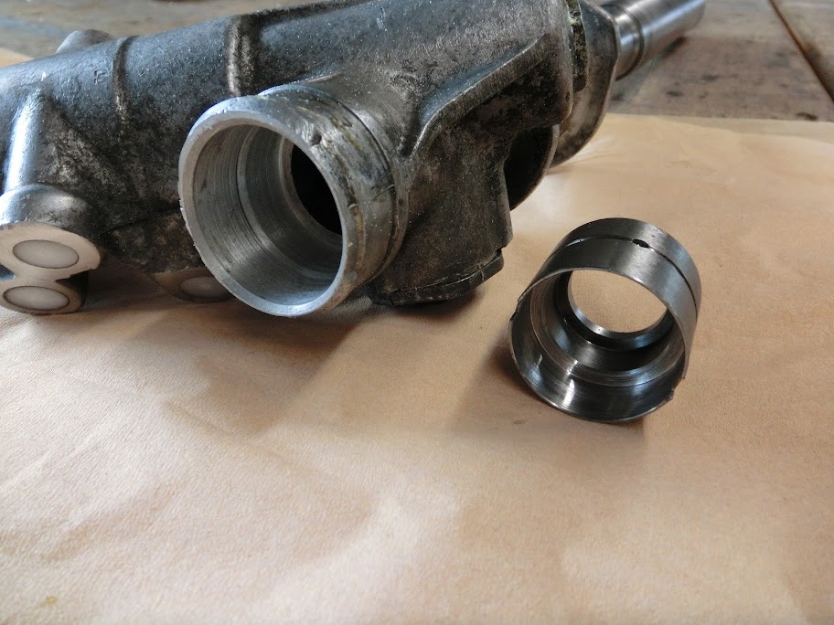
That conical securing collar? Are you talking about that little part on the e-shaft that keeps the slip-on piece in place? There's thread on the e-shaft and the part has inside thread, it's screwed onto the eshaft.
Update
I did some more work on the front suspension and steering bits today
, Had to do a little bit of work on those camberplates, and the pillowball mounts for the lower control arms. Nothing major, just wanted a little bit more clearance here and there.After that I started doing some work on my steering rack. I already depowered it a while ago, but didn't do anything about the steering angle then. This car isn't really a purpose build drift rocket, but I'd like to be able to get the car sideways so I figure a little bit more steering angle wouldn't hurt. I don't want to do short drifting knuckles at this point though, besides drifting they pretty much suck everywhere else in my opinion, especially without power steering and a 15.2:1 rack. Maybe I'll go with electric power steering and drifting knuckles if I end up doing a lot of drifting, but for now I'm just trying to get a little bit more steering rack stroke.
I could use tie-rod spacers and shorten the ends of the tie-rods. It's easy but compromises strength because less thread keeps the tie-rod attached to the steering rack which is kindoff important when driving really fast. It also changes steering geometry a bit. It's also possible to machine the steering rack itself, that way I could keep the stock steering geometry, stock tie-rods and it's just as strong as original. Sounded like the way to go for me, since I can machine the rack myself.
Here you're looking into the left side of the steeringrack with the tie-rod removed. Normally the tie-rod hits that flat spot inside the rack that limits movement. The steering rod however can move further. By machining that flat spot further in it's possible to increase the stroke the steering rack can make. I found that both sides can be machined about 8mm's before there's any chance of running out of gear tooth. It's important that steering stroke is limited by the tie rods hitting the rack instead of the steering rod and pinion gear tooth running out and locking

Right, so in the lathe it goes. I figured maching the rack was easy. I was wrong. Mounting a rack in the lathe like this doesn't work, the machined chamber in the end of the rack isn't in-line with the tube, it's a little bit off

I had to remove the 3-jaw chuck from the lathe, install an independent 4-jaw chuck and use a dial indicator to position the steering rack in the lathe, I hate it when this happens


And succes! Both sides are machined
This is the right side of the rack, The tie-rod normally hits that bushing, now is goes in there

Other side, I guess this works

I spend the rest of the day cleaning up front suspension parts (and seat mounts), crappy job but everything turned out pretty good I guess

I already started painting the steel parts, hopefully I can assemble the front subframe and suspension soon!
Rotary Enthusiast


Joined: Aug 2004
Posts: 1,326
Likes: 9
From: Australia - Perth
what size front rubber are you planning on running. I ended up going back to a PS rack and a Electric hydraulic power steering setup because it was to "heavy" at low speeds. (245's on front)
Senior Member
Joined: Nov 2003
Posts: 533
Likes: 3
From: Sweden
How did it work to depower the steering? Does it not get problem when you cover the holes?
On my FC i depowered my steering but let two hoses go up to a airbleeded canister half filled with oil.
On my FC i depowered my steering but let two hoses go up to a airbleeded canister half filled with oil.
Thread Starter
Joined: Oct 2010
Posts: 605
Likes: 13
From: The Netherlands


Junior Member
Joined: Jan 2011
Posts: 22
Likes: 0
From: Lithuania
I'm using 16x 8,5J et13 wheels, so probably 225-40 tires or whatever I can get my hands on. I think it'll be fine, I'm used to having no power steering, never owned a car with power steering, and � didn't like most of the cars I've driven that had it.
Rotary Enthusiast
Joined: Aug 2004
Posts: 1,326
Likes: 9
From: Australia - Perth
Originally Posted by John Huijben
so probably 225-40 tires or whatever I can get my hands on. I think it'll be fine
It was just the low speed stuff that sucked.
Originally Posted by John Huijben
I depowered it the proper way, the piston is removed and the flexy pinion has been welded solid. There's no oil in my rack, only grease


Joined: Mar 2001
Posts: 31,857
Likes: 3,243
From: https://www2.mazda.com/en/100th/
i had 235/40/17's with the OE manual rack and the 3 rotor, and steering effort was low enough to be a one handed operation, and i'm pretty average size in europe

Thread Starter
Joined: Oct 2010
Posts: 605
Likes: 13
From: The Netherlands
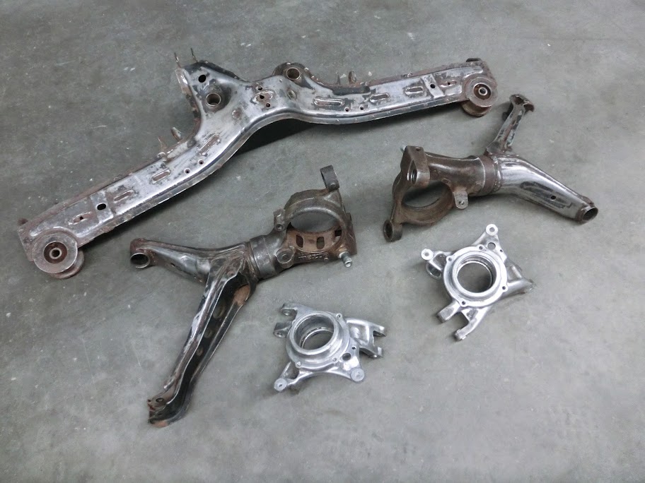
Right, all the front end suspension parts are painted, while the paint hardens I started working on the rear end. The suspension and diff underneath the car was still all 25 year old oem n/a stuff, so needless to say it could use more awesome!
So I pulled the subframe and disassembled it, which was a crappy job since for some reason nothing wanted to come lose. After spending some time breaking boltheads, various tools and a vice I finally ended up with a lot of seperate suspension pieces Also pressed most of the bushings out of there and got most of the dirt of everything so I can do some work.
I'm still not completely sure what I'm going to do with the suspension though. I want to replace a lot of the flexy rubber stuff with delrin of spherical bearings, like I did in the front, and I also want to be able to easily adjust toe and camber settings. I think I'll start with eliminating the DTSS crap, fit spherical bearings to the trailing arms and make the lateral links length-adjustable so I can use them to adjust toe. As far as camber adjustment I'm thinking about making my own independent camber adjusters since I don't like the AWR and MMR units. Don't know about also using a center-adjuster that tilts the subframe though, I might need it to get decent camber but it adjust pinion angle and you can't really use it with solid subframe mounts. Maybe using spherical bearings as subframe mounts is a good idea , solid but still allows center camber adjustment.
So I pulled the subframe and disassembled it, which was a crappy job since for some reason nothing wanted to come lose. After spending some time breaking boltheads, various tools and a vice I finally ended up with a lot of seperate suspension pieces
Also pressed most of the bushings out of there and got most of the dirt of everything so I can do some work.I'm still not completely sure what I'm going to do with the suspension though. I want to replace a lot of the flexy rubber stuff with delrin of spherical bearings, like I did in the front, and I also want to be able to easily adjust toe and camber settings. I think I'll start with eliminating the DTSS crap, fit spherical bearings to the trailing arms and make the lateral links length-adjustable so I can use them to adjust toe. As far as camber adjustment I'm thinking about making my own independent camber adjusters since I don't like the AWR and MMR units. Don't know about also using a center-adjuster that tilts the subframe though, I might need it to get decent camber but it adjust pinion angle and you can't really use it with solid subframe mounts. Maybe using spherical bearings as subframe mounts is a good idea
, solid but still allows center camber adjustment.
John, this thread is amazing.
Not only because the project is exotic and interesting but also because even the mundane aspects are ripe with the promise of weirdness.
I sure hope it meets your expectations.
Not only because the project is exotic and interesting but also because even the mundane aspects are ripe with the promise of weirdness.
I sure hope it meets your expectations.
Right, all the front end suspension parts are painted, while the paint hardens I started working on the rear end. The suspension and diff underneath the car was still all 25 year old oem n/a stuff, so needless to say it could use more awesome!
So I pulled the subframe and disassembled it, which was a crappy job since for some reason nothing wanted to come lose. After spending some time breaking boltheads, various tools and a vice I finally ended up with a lot of seperate suspension pieces Also pressed most of the bushings out of there and got most of the dirt of everything so I can do some work.
I'm still not completely sure what I'm going to do with the suspension though. I want to replace a lot of the flexy rubber stuff with delrin of spherical bearings, like I did in the front, and I also want to be able to easily adjust toe and camber settings. I think I'll start with eliminating the DTSS crap, fit spherical bearings to the trailing arms and make the lateral links length-adjustable so I can use them to adjust toe. As far as camber adjustment I'm thinking about making my own independent camber adjusters since I don't like the AWR and MMR units. Don't know about also using a center-adjuster that tilts the subframe though, I might need it to get decent camber but it adjust pinion angle and you can't really use it with solid subframe mounts. Maybe using spherical bearings as subframe mounts is a good idea, solid but still allows center camber adjustment.
So I pulled the subframe and disassembled it, which was a crappy job since for some reason nothing wanted to come lose. After spending some time breaking boltheads, various tools and a vice I finally ended up with a lot of seperate suspension pieces
Also pressed most of the bushings out of there and got most of the dirt of everything so I can do some work.I'm still not completely sure what I'm going to do with the suspension though. I want to replace a lot of the flexy rubber stuff with delrin of spherical bearings, like I did in the front, and I also want to be able to easily adjust toe and camber settings. I think I'll start with eliminating the DTSS crap, fit spherical bearings to the trailing arms and make the lateral links length-adjustable so I can use them to adjust toe. As far as camber adjustment I'm thinking about making my own independent camber adjusters since I don't like the AWR and MMR units. Don't know about also using a center-adjuster that tilts the subframe though, I might need it to get decent camber but it adjust pinion angle and you can't really use it with solid subframe mounts. Maybe using spherical bearings as subframe mounts is a good idea
, solid but still allows center camber adjustment.I'm really looking forward to what you're going to do with the individual camber links/ might steal whatever idea you come up with
Thread Starter
Joined: Oct 2010
Posts: 605
Likes: 13
From: The Netherlands
That makes three of us
Joined: Mar 2001
Posts: 31,857
Likes: 3,243
From: https://www2.mazda.com/en/100th/
i have five ideas.
1. the hard way. cut the trailiing arm, and reweld it with less camber.
2. the lazy way. don't run the car that low, and you can make a moderate adjustment with the camber link.
3. how about moving the pivot point of the inner dogbone? the US guys usually can't because we're racing, and it wouldn't be legal, but you're not!
4. the expensive way. run individual camber adjusters, and the camber link, and between all three of those it should work out.
4a. make the diff mount adjustable so that you can move the subframe and then readjust the pinion angle.
5 slide into a curb, just right.....
Center bar is not enough to zero the rear camber, there are two brands of individual camber links, the ones made by MazdaTrix and AWR. We have a 20b FC running AWR units with a MazdaTrix center link and its aligned to have -.5 degrees of camber.
There are also supernow links from japan but they're just fixed shorter than stock links.
Yeah I know, ideally I want to make solid subframe mounts, and a solid non-adjustable center bar and be done with it. Problem is that I'm not sure if I can get enough adjustment with independent camber adjusters alone. Results from other people vary a lot, some get enough adjustment, some need the center bar too. To dial out the negative camber the trailing arm needs to move towards the subframe, but there is only a bit of adjustment possible before the trailing arm hits it.
like j9fd3s said, how much you need to dial out is highly dependent on ride height.
I'm currently running -2* with just individual links and it's fine. I can take a picture of how much more adjustment I have if you want.
remember the less camber you run in the back the less tire you can fit
you're heavily limited by the control arm shape on the inside.I think you should just build some tubular rear control arms with more tire clearance and less camber... make 2 sets please

another thing to think about is offsetting the bushings in the triaxial hub to have less camber then adjust it as needed with the links.
Thread Starter
Joined: Oct 2010
Posts: 605
Likes: 13
From: The Netherlands
how much camber are you planning on running?
like j9fd3s said, how much you need to dial out is highly dependent on ride height.
I'm currently running -2* with just individual links and it's fine. I can take a picture of how much more adjustment I have if you want.
remember the less camber you run in the back the less tire you can fit you're heavily limited by the control arm shape on the inside.
I think you should just build some tubular rear control arms with more tire clearance and less camber... make 2 sets please
another thing to think about is offsetting the bushings in the triaxial hub to have less camber then adjust it as needed with the links.
like j9fd3s said, how much you need to dial out is highly dependent on ride height.
I'm currently running -2* with just individual links and it's fine. I can take a picture of how much more adjustment I have if you want.
remember the less camber you run in the back the less tire you can fit
you're heavily limited by the control arm shape on the inside.I think you should just build some tubular rear control arms with more tire clearance and less camber... make 2 sets please
another thing to think about is offsetting the bushings in the triaxial hub to have less camber then adjust it as needed with the links.
I'm not really sure about what camber I want, probably 1,5 - 2 deg or something like that but I'd like to do the suspension right the first time, so I don't have to do more modifications when I find out I can't get the camber where I want it if I decide to lower it a bit more.
I think the easiest way is to just fit an adjustable center bar and 2 individual camber adjusters and be done with it. Funny you mentioned building tubular rear control arms. I just spend the evening mocking up suspension pieces on the car, finding out how the FC suspension works, and figuring out how it can be made better. Now I'm even more confused than I was before

yeah, but the dynamic toe (bump steer) is damn near amazing (0.005" of bump steer throughout my entire rear suspension travel). I've heard mazdaspeed used to sell different rear control arms with far less camber when lowered... but they've been discontinued for a long time.
Another thing you could do that I've been thinking about is to shave the tops of the subframe (and differential) bushings down to get the sub-frame closer to the body. This will cure some of the camber gain from lowering the car.
I haven't tried it though, so I'm not sure if it would hit anything...
I haven't tried it though, so I'm not sure if it would hit anything...
Thread Starter
Joined: Oct 2010
Posts: 605
Likes: 13
From: The Netherlands
Yeah, I know the FC suspension can be made to work pretty good! But fitting a camberlink and center bar is still kindoff bandaiding the suspension to work at a different ride height than what it was originally designed to work at. Also with the dtss eliminated the trailing arm is far heavier than it needs to be. I might just go ahead and perform all the mods to the FC suspension that others have done and be done with it, but I can't help thinking about fabricating something like this:


It's a regular trailing arm setup with independent links. The upper one adjusts toe and the lower one adjusts camber. The links go on the lateral link point on the stock subframe. Benefits are that I can change the amount of camber the suspension gains (or loses) on compression, camber adjustment range is far greater and its very easy to adjust on the car, no flex, far lighter than stock, possibility to fit wider rubber, possibility to fit almost any brake setup and very easily rebuildable with easy to get parts. Dynamic toe is about 0.3 deg with 80mm's of suspension travel, It gains about 1.8 deg of camber with that travel but I can easily adjust that to anything I want. I don't know a lot about suspension stuff but I think it can work. There is some work involved but nothing really outrageous. What do you guys think? Crap idea or a viable option?
It's a regular trailing arm setup with independent links. The upper one adjusts toe and the lower one adjusts camber. The links go on the lateral link point on the stock subframe. Benefits are that I can change the amount of camber the suspension gains (or loses) on compression, camber adjustment range is far greater and its very easy to adjust on the car, no flex, far lighter than stock, possibility to fit wider rubber, possibility to fit almost any brake setup and very easily rebuildable with easy to get parts. Dynamic toe is about 0.3 deg with 80mm's of suspension travel, It gains about 1.8 deg of camber with that travel but I can easily adjust that to anything I want. I don't know a lot about suspension stuff but I think it can work. There is some work involved but nothing really outrageous. What do you guys think? Crap idea or a viable option?