
Update on Project Gus

Update on Project Gus
Thought I'd post a quick update on project Gus. I got the engine and transmission out this weekend, and work continues on the carburetor. I'll let the pictures do the talking...
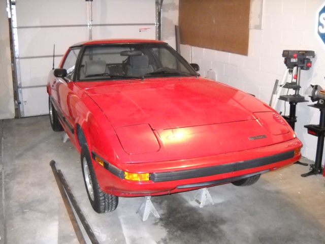
Here's a shot of Gus up on the Jackstands after the engine removal.
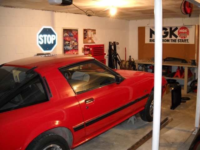
Here's the garage setup. Recently moved, and the new house has a bigger garage. I've got a lot more room to work on the car. It's really nice.
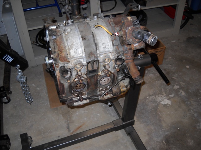
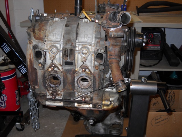
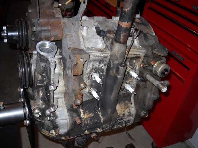
I am going to get an engine stand adapter from Pineapple Racing so that the engine isn't hanging from the front cover like that. But it works for the time being. I'm heavily contemplating a rebuild and streetport for this engine. I went ahead and pressure washed it to get the heavy crud off. It was incredibly nasty before.
Here's a shot of Gus up on the Jackstands after the engine removal.
Here's the garage setup. Recently moved, and the new house has a bigger garage. I've got a lot more room to work on the car. It's really nice.
I am going to get an engine stand adapter from Pineapple Racing so that the engine isn't hanging from the front cover like that. But it works for the time being. I'm heavily contemplating a rebuild and streetport for this engine. I went ahead and pressure washed it to get the heavy crud off. It was incredibly nasty before.
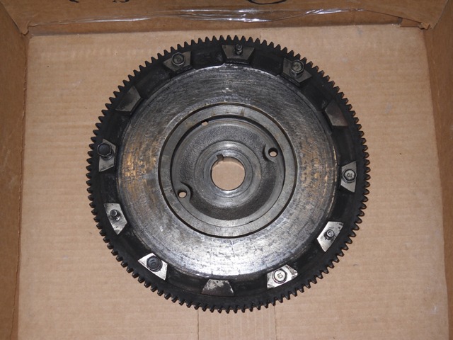
Got the monster stock flywheel pulled off too. I am going to switch to a Fidanza aluminum flywheel. It should save some weight and also let the 12A rev up quicker. I've used the RB light steel flywheel in the past, but I want to try something even more drastic this time.
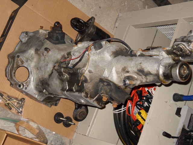
Sideways picture of the 5 speed. I'm thinking about switching to a Miata gearset and keeping the FB bellhousing and tail section.
The Nikki carb with the primary and secondary venturis removed. I sent them to Sterling a while back before he stopped taking orders. Hopefully he'll give them his golden touch and get them sent back to me. The carb is going to be the best part of this whole build.
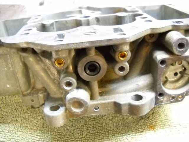
Here are some modifications that I made to the main body of the Nikki carb. I removed the OMP nipples since I'll be running premix. I tapped the holes and put set screw in each one. I'll JB Weld them in during the final assembly. It gives the carb a cleaner look, and I don't have the useless nipples there I don't need anymore. I also removed the nipple for the sub zero start assist and got a metric plug from McMaster Carr that is the right size.
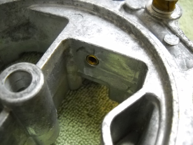
I took out the choke plate and linkage to help increase the airflow thru the air horn. I tapped the holes left over by the choke linkage to take a 1/4-20 set screw. This will give a cleaner look, and also close up the hole. I don't have to worry about air sneaking in under the filter this way.
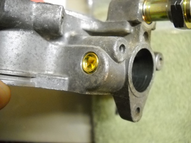
One final hole that I plugged on the front of the Nikki. I removed the brass elbow on the front of the carb. I tapped it to take a set screw also. After you pull it out, the big brass bung can be mounted in a bench vise and it pulls out from the front pretty easily too. I'll be tapping in a freeze plug to seal up the large hole during final assembly.
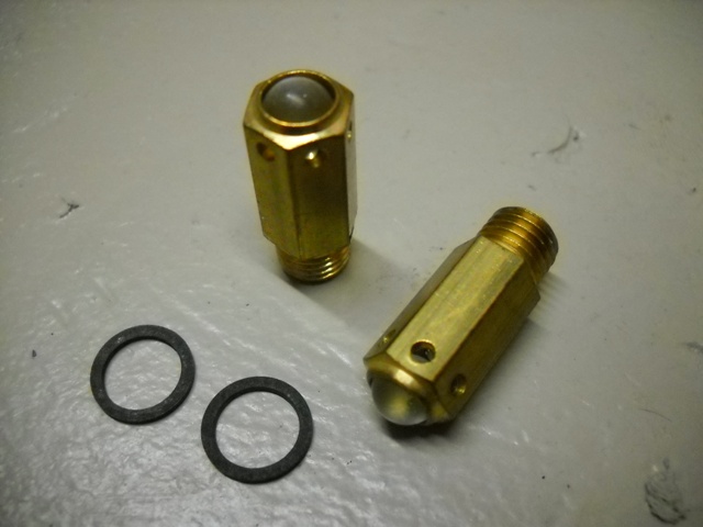
I got some old school Nikki grose jets from a fellow forum member. Here is a close up shot of them. These are the grose jets from the old Mazdaspeed catalog. They don't stick like the needle and seat setup does.
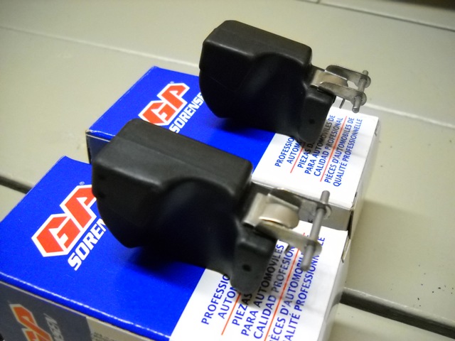
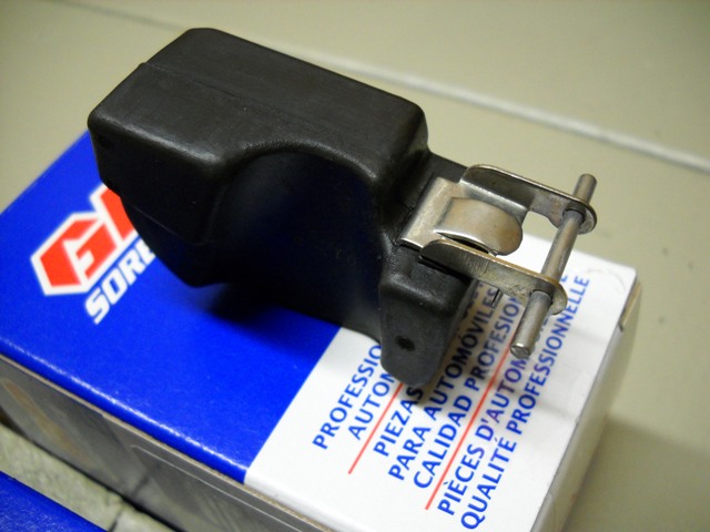
I ordered some old style large Rx3 floats from Autozone's website. These are the key to eliminating the bogging in hard left hand turns. The stock Nikki suffers very badly from this. Both of the floats are the same, but I've heard from others that it really doesn't matter. You can just put both of them in the Nikki and it works great. You don't have to have a left/right pair necessarily. For some reason Autozone only carries one of the two floats. I just bought a pair of left ones and will give it a go. I've heard good results from others who did this.
That's about it for now. Stay tuned! Hoping to get the Nikki assembled soon. Waiting on some stuff to come back from Sterling. Hopefully it gets here soon.


Yeah, I'm pretty excited about the carb. I've got a lot of time invested in it. I've done lots of research, and thanks to Sterling's website I actually understand how this thing works. Never thought I'd figure it out. I'm excited to start putting it back together though. It's gonna be a big improvement over stock.


I didn't really intend to rebuild it when I pulled it out. Mainly just clean and paint it. But then I thought, "I always just paint the engine and then put it back in. I'm going to rebuild this one." Then I figured, if I've got it opened up maybe I'll just go ahead and streetport the thing. We'll see how it goes.
My plan for now is to finish the carb, then get a couple of engine rebuilding DVDs to watch, and then start opening up the 12A.
Jamie
My plan for now is to finish the carb, then get a couple of engine rebuilding DVDs to watch, and then start opening up the 12A.
Jamie
Trending Topics

You'd better open up the 12A soon. Pressure washing always lets water get in which does cause rust in places you don't want it. I feel it's better to wash the parts after disassembly. So what if your hands get a little dirty. You prevent rust!
Do me a favor and put the flywheel back on so you can have something to hold the shaft while you loosen the front bolt. More on this explained later.
Congrats on taking the first step, which is engine removal! Now drain the oil and remove all 22 little oil pan bolts. A putty knife works well for getting between the pan lip and engine. Then a couple of flathead screwdrivers shoved here and there to carefully and slowly seperate the pan if the sealant is still really in good shape. This protects the pan lip so it doesn't get bent or out of "true". One note is to add one long botl in the same thread pitch and diameter (6mm x 1.00). This is to hold the pan so it doesn't drop off and splash oil all over your knee.
You don't need a pineapple or whatever other engine stand adapter. I use the stock arms that came with my engine stand. All four, even though three would still be fine (you gotta take out your studs in the front plate and use bolts). But then again I don't use the stand until engine assembly. One note if you do use the stand arms for assembly, I had to trim some of the steel from the stand head to clear the heater tube if you've got a long beehive T shaped tube in your rear plate. If you dry stack your engine, you'll see what I'm talking about.
For dissassembly I just hang it from the engine crane to remove the oil pan bolts and pan. Also the pickup tube and front cover oil pressure reg come off before I let it down on a drip pan to catch fluids as the engine comes apart. Good idea to remove the intermediate plate coolant drain bolt and hold a coffee can under it while it's still up in the air. I also don't strip the top of the engine until it's down. Easier to take off carbs and rats nests etc when it's low.
Once lowered down on the drip pan, this is where I loosen the front 19mm bolt and remove the flywheel. You have a lot of stability when positioned like this. If the factory was the last time the 19mm bolt was tightened, it should come off with just an impact wrench. However if some hotshot hamfisted mechanic tightened the bolt, it's a bear to take off. Be sure to lock the flywheel before you attempt to remove the 19mm bolt. If you don't have a flywheel locker, you can throw on the rear counterweight (just snug the 54mm nut but hand, don't actually tighten it) and place a piece of angle iron bolted to two of the bellhousing bolts; this acts as a very sturdy shaft stopper and is what I use when I'm doing an aftermarket flywheel on an engine, or when a stock flywheel isn't within easy reach.
I do have the Mazdatrix flywheel stopper, which works brilliantly, as well. But I have the earlier version made from a piece of ring gear lol, not this purpose-made unit.

You may need to use heat to burn off the threadlock that's often used on the front bolt. Crappy shops like Hayes Rotary always used a thread locker on the actual threads of the bolt. Stupid! Rapid Rotary also did something bad making the 19mm bolts next to impossible to remove. On these, I'd have to take a 1" hole saw (with drill bit removed or shortened) and cut through the flat part of the bolt. This lets the surrounding steel lessen its grip and an impact can then remove the bolt. They were some of the worst I've ever dealt with. In contrast, factory tightened have always been the best. When I tighten mine down, I use a little bit of RTV on the copper crush washer to seal against oil leakage and it acts as a slow speed lubricant to get the torque really accurate. I use factory recommended 70 to 80 foot pounds on series 3 and older engines. When removal time comes (for a quickie rebuild or if I'm porting more agressively), bolts I've tightened always come off as nicely as factory.
If you're interested in advice about porting, considering that you're going to be using a Nikki on this engine, with the awesome '70s manifold, I'd recommend porting to 74 spec. Also don't hog the runners as this leads to crappy low RPM with only a small gain up top. Again you're using factory parts, not some weber IDA setup with an aftermarket manifold and huge runners, so please don't hog out the runners in the engine and especially do not touch the intake manifold. I'll come to your house.
I suppose you could streetport, but I'll tell you something that I just experienced yesterday. I just got a fresh rebuilt 12A running on a stock carb and stock 81-85 (the worst) manifold. The engine got the largest streetport I've ever done. Something like 65 or more degrees closing and a couple degrees earlier opening (a couple mm anyway). I used a pineapple streetport as my template. This engine was able to idle at 725-750rpm within 20 minutes of run time. I could have gone lower but that was where this carb was previously set, which I then set it up closer to 1k for easier driving. Just waiting on a clutch master rebuild kit so I can test drive it. Will it have any low end torque? We'll see.
The reason it could idle this low was because I left the runners stock with their factory rough casting (there's a reason for this, which I'll get to). If I had hogged out the runners, I'd be lucky if it would idle at 1100 this early. The ports really are that large that you would normally hog the runners as well, but I'm very glad I didn't. And I'll tell you why. This engine will get a turbo at some point so it's ok to port it the way I did, to delay closing for as long as possible to aid chamber filling under boost. It's also ok to leave the runners alone as the boost will cover for any inadequacies, due to their size, that may exist.
Now if it was NA-only, I'd have hogged the runners seeing how large the ports are, and expect power to come in between 4k and 9k. But because it's getting an OER carb (OER looks like a weber DCOE if you didn't know; I didn't before lol) that's basically boost-prepped from the factory, it's getting a turbo. However while it's breaking in in NA mode, the rpms have to be kept low, so the time this engine spends in the lower rpms, it's going to be far more pleasant thanks to my thinking ahead and not following typical info you'd find here and elsewhere.
Perhaps another reason for choosing to keep at least a little low RPM power is because this engine is going into a B2000. It's keeping the stock 83-85 flywheel as well. By the way if this engine wasn't getting boosted, I'd have gone with 74 spec ports. It's for a truck!
Getting back to what I was talking about, for your engine, I'd recommend 74 spec all the way! Factory intake parts on factory port timing that's still larger than a stock 12A. You (the -7-) can't lose! Infact I'd venture so far as to say the runner lengths in the 70s manifold match 74 ports as that was what the factory used at that time. Then again the engine this particular manifold originally came on probably had the smaller 76-85 12A port size by then, as channeled manifolds hadn't come out in 74. I'm thinking closer to the later 70s. I know 76 had a reverse runner manifold which was still fully separate. Maybe 77-78? Like an RX-3 or something?
Oh and here's another nice confirmation. The 12A I built for PercentSevenC had porting to 74 spec and it used one of these awesome channeled '70s manifolds. It also had a stripped '84-'85 Nikki with 95 primary jets and 60 or 70 primary air bleeds. The exhaust ports were ported up 2mm (until factory bevel was gone, then re-added). I think they were also ported wider by 2mm on each side, but you'll have to ask him. This engine lacked a little bit of low end compared to a factory set of ports, but get it above something like 1800 and it would come alive. Then when you open the secondaries it literally felt like it had a Camden on it. Of course a light steel flywheel and a full RB dual pipe "streetport" exhaust were put to good use. That was my most favorite setup for an FB, ever (so far lol).
You said you're going with an aluminum flwyheel. This will obviously reduce some of your inertia, leading to slightly more complicated launches, which you are already prepared for. But do yourself a favor and seriously consider 74 ports. Heck I'm doing them in three engines coming up this spring, for two REPUs and my rotary MG Midget. The REPUs are both 74 so it's year-correct. One REPU is getting a Camden and the other is getting a blow-through Holley. The name of the game for them is keeping as much low end as possible while not strictly adhering to NA rules since both will have a boosted intake. The MG is getting a factory matched 74 carb and an unusual 76 reverse runner manifold. It's not strictly 74, but I've test ran this combo as a temp setup in this car a few years ago on a tired 3B engine and it knocked my socks off, so it's getting a purpose-built R5/Y engine this time. Color matched side plates (blue to match the car), aluminum on aluminum flywheel mod, another light steel flywheel, complete 2.5" exhaust, the works!
Sorry to fill your thread with so much of my stuff, but I hope these examples will influence you in a positive way. And by the way if you're not really sure how large a 74 spec port is, if you have any T2 or FD end plates lying around, the secondaries open and close at 74 spec! Only the very bottom of the port is a little different between S3-older and S4+, which you'll see if you make a paper template and lay it on your 12A plates. You can ignore the bottom part. The opening is exactly the same. Only the closing edge changes. I'd smooth the opening edge though. Get rid of the sharp 90� edge. Also blend the new closing edge with the current roof-height of your port. In other words, "raise the roof" as far back as you can so the transition from runner to port is smooth and factory-like, not just some short little ramp up to the new closing timing. If you've never ported before, this might not make sense yet, but once you get into it, it'll become more clear.
Well that was longer than I intended. Good luck.
Do me a favor and put the flywheel back on so you can have something to hold the shaft while you loosen the front bolt. More on this explained later.
Congrats on taking the first step, which is engine removal! Now drain the oil and remove all 22 little oil pan bolts. A putty knife works well for getting between the pan lip and engine. Then a couple of flathead screwdrivers shoved here and there to carefully and slowly seperate the pan if the sealant is still really in good shape. This protects the pan lip so it doesn't get bent or out of "true". One note is to add one long botl in the same thread pitch and diameter (6mm x 1.00). This is to hold the pan so it doesn't drop off and splash oil all over your knee.
You don't need a pineapple or whatever other engine stand adapter. I use the stock arms that came with my engine stand. All four, even though three would still be fine (you gotta take out your studs in the front plate and use bolts). But then again I don't use the stand until engine assembly. One note if you do use the stand arms for assembly, I had to trim some of the steel from the stand head to clear the heater tube if you've got a long beehive T shaped tube in your rear plate. If you dry stack your engine, you'll see what I'm talking about.
For dissassembly I just hang it from the engine crane to remove the oil pan bolts and pan. Also the pickup tube and front cover oil pressure reg come off before I let it down on a drip pan to catch fluids as the engine comes apart. Good idea to remove the intermediate plate coolant drain bolt and hold a coffee can under it while it's still up in the air. I also don't strip the top of the engine until it's down. Easier to take off carbs and rats nests etc when it's low.
Once lowered down on the drip pan, this is where I loosen the front 19mm bolt and remove the flywheel. You have a lot of stability when positioned like this. If the factory was the last time the 19mm bolt was tightened, it should come off with just an impact wrench. However if some hotshot hamfisted mechanic tightened the bolt, it's a bear to take off. Be sure to lock the flywheel before you attempt to remove the 19mm bolt. If you don't have a flywheel locker, you can throw on the rear counterweight (just snug the 54mm nut but hand, don't actually tighten it) and place a piece of angle iron bolted to two of the bellhousing bolts; this acts as a very sturdy shaft stopper and is what I use when I'm doing an aftermarket flywheel on an engine, or when a stock flywheel isn't within easy reach.
I do have the Mazdatrix flywheel stopper, which works brilliantly, as well. But I have the earlier version made from a piece of ring gear lol, not this purpose-made unit.
You may need to use heat to burn off the threadlock that's often used on the front bolt. Crappy shops like Hayes Rotary always used a thread locker on the actual threads of the bolt. Stupid! Rapid Rotary also did something bad making the 19mm bolts next to impossible to remove. On these, I'd have to take a 1" hole saw (with drill bit removed or shortened) and cut through the flat part of the bolt. This lets the surrounding steel lessen its grip and an impact can then remove the bolt. They were some of the worst I've ever dealt with. In contrast, factory tightened have always been the best. When I tighten mine down, I use a little bit of RTV on the copper crush washer to seal against oil leakage and it acts as a slow speed lubricant to get the torque really accurate. I use factory recommended 70 to 80 foot pounds on series 3 and older engines. When removal time comes (for a quickie rebuild or if I'm porting more agressively), bolts I've tightened always come off as nicely as factory.
If you're interested in advice about porting, considering that you're going to be using a Nikki on this engine, with the awesome '70s manifold, I'd recommend porting to 74 spec. Also don't hog the runners as this leads to crappy low RPM with only a small gain up top. Again you're using factory parts, not some weber IDA setup with an aftermarket manifold and huge runners, so please don't hog out the runners in the engine and especially do not touch the intake manifold. I'll come to your house.
I suppose you could streetport, but I'll tell you something that I just experienced yesterday. I just got a fresh rebuilt 12A running on a stock carb and stock 81-85 (the worst) manifold. The engine got the largest streetport I've ever done. Something like 65 or more degrees closing and a couple degrees earlier opening (a couple mm anyway). I used a pineapple streetport as my template. This engine was able to idle at 725-750rpm within 20 minutes of run time. I could have gone lower but that was where this carb was previously set, which I then set it up closer to 1k for easier driving. Just waiting on a clutch master rebuild kit so I can test drive it. Will it have any low end torque? We'll see.
The reason it could idle this low was because I left the runners stock with their factory rough casting (there's a reason for this, which I'll get to). If I had hogged out the runners, I'd be lucky if it would idle at 1100 this early. The ports really are that large that you would normally hog the runners as well, but I'm very glad I didn't. And I'll tell you why. This engine will get a turbo at some point so it's ok to port it the way I did, to delay closing for as long as possible to aid chamber filling under boost. It's also ok to leave the runners alone as the boost will cover for any inadequacies, due to their size, that may exist.
Now if it was NA-only, I'd have hogged the runners seeing how large the ports are, and expect power to come in between 4k and 9k. But because it's getting an OER carb (OER looks like a weber DCOE if you didn't know; I didn't before lol) that's basically boost-prepped from the factory, it's getting a turbo.
However while it's breaking in in NA mode, the rpms have to be kept low, so the time this engine spends in the lower rpms, it's going to be far more pleasant thanks to my thinking ahead and not following typical info you'd find here and elsewhere.Perhaps another reason for choosing to keep at least a little low RPM power is because this engine is going into a B2000. It's keeping the stock 83-85 flywheel as well. By the way if this engine wasn't getting boosted, I'd have gone with 74 spec ports. It's for a truck!
Getting back to what I was talking about, for your engine, I'd recommend 74 spec all the way! Factory intake parts on factory port timing that's still larger than a stock 12A. You (the -7-) can't lose! Infact I'd venture so far as to say the runner lengths in the 70s manifold match 74 ports as that was what the factory used at that time. Then again the engine this particular manifold originally came on probably had the smaller 76-85 12A port size by then, as channeled manifolds hadn't come out in 74. I'm thinking closer to the later 70s. I know 76 had a reverse runner manifold which was still fully separate. Maybe 77-78? Like an RX-3 or something?
Oh and here's another nice confirmation. The 12A I built for PercentSevenC had porting to 74 spec and it used one of these awesome channeled '70s manifolds. It also had a stripped '84-'85 Nikki with 95 primary jets and 60 or 70 primary air bleeds. The exhaust ports were ported up 2mm (until factory bevel was gone, then re-added). I think they were also ported wider by 2mm on each side, but you'll have to ask him. This engine lacked a little bit of low end compared to a factory set of ports, but get it above something like 1800 and it would come alive. Then when you open the secondaries it literally felt like it had a Camden on it. Of course a light steel flywheel and a full RB dual pipe "streetport" exhaust were put to good use. That was my most favorite setup for an FB, ever (so far lol).
You said you're going with an aluminum flwyheel. This will obviously reduce some of your inertia, leading to slightly more complicated launches, which you are already prepared for. But do yourself a favor and seriously consider 74 ports. Heck I'm doing them in three engines coming up this spring, for two REPUs and my rotary MG Midget.
The REPUs are both 74 so it's year-correct. One REPU is getting a Camden and the other is getting a blow-through Holley. The name of the game for them is keeping as much low end as possible while not strictly adhering to NA rules since both will have a boosted intake. The MG is getting a factory matched 74 carb and an unusual 76 reverse runner manifold. It's not strictly 74, but I've test ran this combo as a temp setup in this car a few years ago on a tired 3B engine and it knocked my socks off, so it's getting a purpose-built R5/Y engine this time. Color matched side plates (blue to match the car), aluminum on aluminum flywheel mod, another light steel flywheel, complete 2.5" exhaust, the works!Sorry to fill your thread with so much of my stuff, but I hope these examples will influence you in a positive way. And by the way if you're not really sure how large a 74 spec port is, if you have any T2 or FD end plates lying around, the secondaries open and close at 74 spec! Only the very bottom of the port is a little different between S3-older and S4+, which you'll see if you make a paper template and lay it on your 12A plates. You can ignore the bottom part. The opening is exactly the same. Only the closing edge changes. I'd smooth the opening edge though. Get rid of the sharp 90� edge. Also blend the new closing edge with the current roof-height of your port. In other words, "raise the roof" as far back as you can so the transition from runner to port is smooth and factory-like, not just some short little ramp up to the new closing timing. If you've never ported before, this might not make sense yet, but once you get into it, it'll become more clear.
Well that was longer than I intended. Good luck.

Great info Jeff. I'll keep all this handy, and I will definitely take your recommendation on the 74 spec ports. I don't want to lose that low end punch just for the sake of saying I have a street ported engine. The 74 spec ports should work very well with the sweet manifold you provided, and the tweaked carburetor I'm working on.
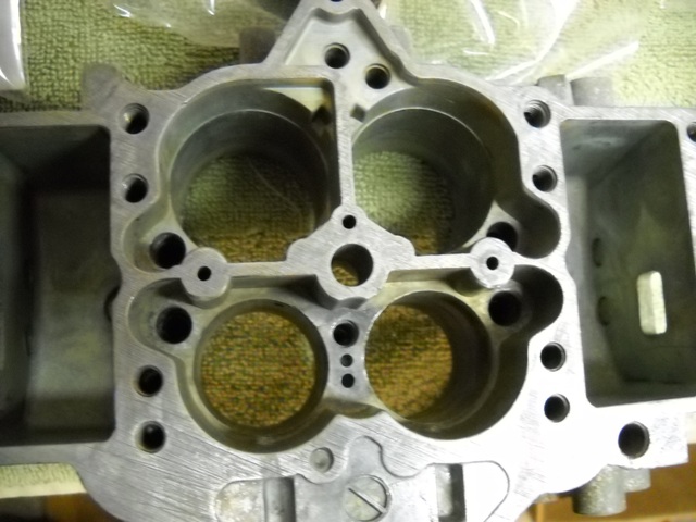
Speaking of the manifold, I'd like to get your input on one area. I have been considering massaging the top carburetor side of the manifold per Rx7carl's findings from back in the day. Carl deduced from his flow bench that the best flow numbers on a stock manifold could be attained by porting the top of the manifold as so:
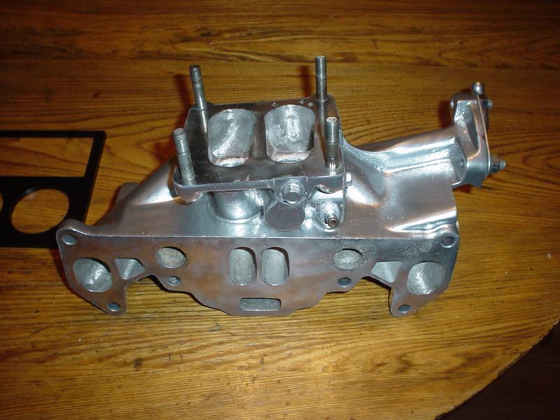
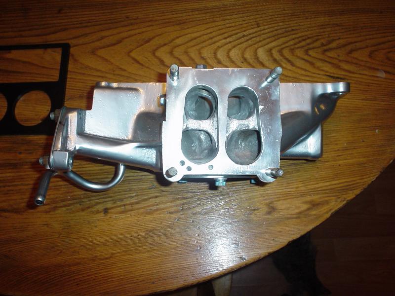
That is Vipernicus42's stock intake manifold after Carl worked it over. Do you think there would be any benefit to modifying the top of the old school intake manifold to this design? Essentially making a tangent line between the primary and secondary runners?
Jamie
Speaking of the manifold, I'd like to get your input on one area. I have been considering massaging the top carburetor side of the manifold per Rx7carl's findings from back in the day. Carl deduced from his flow bench that the best flow numbers on a stock manifold could be attained by porting the top of the manifold as so:
That is Vipernicus42's stock intake manifold after Carl worked it over. Do you think there would be any benefit to modifying the top of the old school intake manifold to this design? Essentially making a tangent line between the primary and secondary runners?
Jamie
I'm going to say maybe. I did that to a much lesser extent on my other channeled 70s manifold. That's the one that was mistaken for a Camden.
Oh another piece of advice. Fill the ACV port in the intermediate plate with quicksteel or some other thick putty. This keeps heat out of the manifold. After filling the ACV port, you don't even need a cover plate on the manifold. Plus you are free to add some freeze plugs to the coolant ports in the engine. I call it the cool manifold mod (which is ironic because you're not mdding the manifold at all). So many people plug the coolant ports but don't do anything with the ACV port which leads to a super-heated manifold. Something to avoid.
Oh another piece of advice. Fill the ACV port in the intermediate plate with quicksteel or some other thick putty. This keeps heat out of the manifold. After filling the ACV port, you don't even need a cover plate on the manifold. Plus you are free to add some freeze plugs to the coolant ports in the engine. I call it the cool manifold mod (which is ironic because you're not mdding the manifold at all). So many people plug the coolant ports but don't do anything with the ACV port which leads to a super-heated manifold. Something to avoid.
When you were saying don't touch the manifold, you were referring to the engine side of the manifold that everyone always wants to make taller, right? Thinking that if they match the intake manifold ports to the engine ports they magically get power? I have no intent of doing that...
Good because I will come to your house.
Just ask peejay about his findings when he port matched an FB manifold. It killed velocity or messed up the anti-reversion properties or something. The take-away I got from his testing is DON'T DO IT! Or LEAVE IT ALONE! Either is valid.
Just ask peejay about his findings when he port matched an FB manifold. It killed velocity or messed up the anti-reversion properties or something. The take-away I got from his testing is DON'T DO IT! Or LEAVE IT ALONE! Either is valid.
I'm getting ready to go out and Paul-Yaw-ify the timing marks on my main e-shaft pulley. When I'm all done, I'm planning to set the engine to around 24 deg BTDC on the leading. According to Yaw, the 12A should make peak power somewhere around this point. So, in order to get there I need to add some timing marks to the stock pulley.
I found the old school writeup here:
http://www.rhinoracing.com/yaw/timing.htm
I love old school stuff....
Jamie
I found the old school writeup here:
http://www.rhinoracing.com/yaw/timing.htm
I love old school stuff....
Jamie
Uhg, I wouldn't do the yaw marking method. It's kinda dumb. He converts the correct metric makrs over to inches and uses masking tpae which CAN STRETCH! Cool idea, bad execution. The better way is to take a long thin tape measure that's marked for metric and you;ll see the stock marks are already 20 degrees (or 20mm) apart. Just mark in between them and there's your 10 degree split (don't use 8 as it tends to break trailing spark plugs as many people following yaw's advice discovered). Also you don't need to rev to 4k to set 24 degrees. The dizzy does that automatically if you set it to zero or TDC at idle. But you also must be careful here. If your pulley and hub set are not original, chances are the marks are already off.
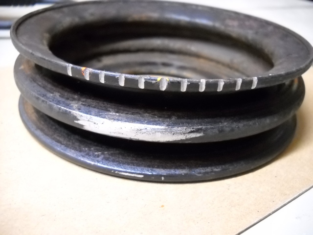
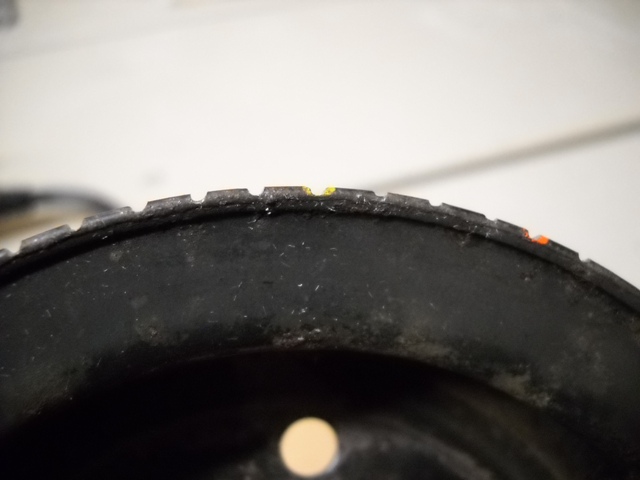
I got the new marks put into the pulley like you described Jeff. I found one of my wife's plastic flexible tape measures that is used for sewing. It wrapped around the pulley very nicely and allowed me to put a mark every 5mm like you described. I went ahead and marked the pulley every 5 degrees BTDC and ATDC up to a maximum of 25 degrees. That way I know that the middle mark is still TDC.
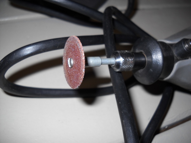
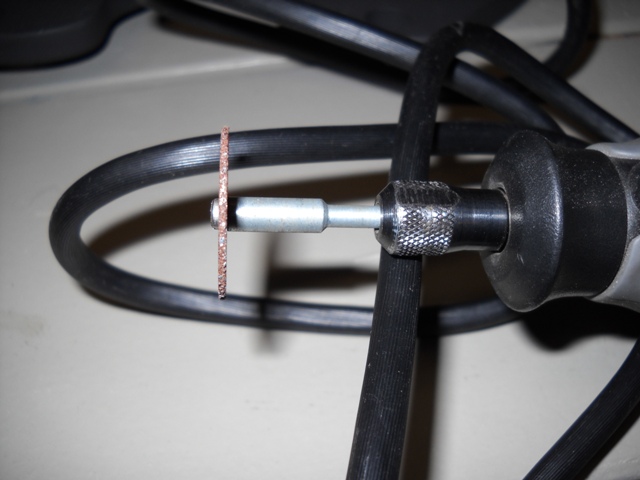
I put a small pencil mark every 5mm and then used the thin grinding wheel on my dremel to notch each pencil mark. The notches are a little bit wider than I wanted, but they are nice and deep. I won't have to worry about losing them to rust or paint buildup.
Tomorrow night I'm going to clean the pulley up, and paint it gloss black. After it's dry I'm going to put a dot of yellow on TDC, and repaint the rest of the timing marks with red paint. Here are some pictures of where I stand right now....
Hmm, depending on the dizzy, it should mechanically advance either 20 degrees or 25 degrees. I believe the 12A units go 20 and the GSL-SE goes 25 (Ask j9fd3s as he ought to know). What yaw is recommending in reality is an idle at 5� advanced. Is that a good idea? Not exactly sure.
Usually I'd find that when I would try to set my timing to 24� at 4k rpm, when it returns to idle, it's right on the yellow (L) mark. This might mean I was using a GSL-SE dizzy at the time. It's honestly been a while. Perhaps it would be best for you, since you should have easy access to the pulley right now, to go ahead and mark it for 25� advance BTDC and another mark 10� after top dead center (this one between the L and T stock marks). That way you have only the marks that matter and not a bunch of notches which require you to count while a) reving to a steady 4k, b) trying to differentiate one mark from another, c) what if there is some ignitor jitter? and d) it looks a lot cleaner. But that's just my semi-humble opinion.
Usually I'd find that when I would try to set my timing to 24� at 4k rpm, when it returns to idle, it's right on the yellow (L) mark. This might mean I was using a GSL-SE dizzy at the time. It's honestly been a while. Perhaps it would be best for you, since you should have easy access to the pulley right now, to go ahead and mark it for 25� advance BTDC and another mark 10� after top dead center (this one between the L and T stock marks). That way you have only the marks that matter and not a bunch of notches which require you to count while a) reving to a steady 4k, b) trying to differentiate one mark from another, c) what if there is some ignitor jitter? and d) it looks a lot cleaner. But that's just my semi-humble opinion.
Woah you posted that while I was typing. Interesing. I've used a small triangle file. Then filled with white paint. I feel a dremel is too big here.
That's a lot of marks! Hopefully you won't run into the potential problems I listed above.
That's a lot of marks! Hopefully you won't run into the potential problems I listed above.

One final hole that I plugged on the front of the Nikki. I removed the brass elbow on the front of the carb. I tapped it to take a set screw also. After you pull it out, the big brass bung can be mounted in a bench vise and it pulls out from the front pretty easily too. I'll be tapping in a freeze plug to seal up the large hole during final assembly.
That's actually a pretty good job on the pulley marking. Very thorough. Good choice on the sewing measuring tape. It's what I use, made of some sort of cloth/fabric.
Hey, did you happen to catch that the circumference of the pulley works out to be 360mm? Think Mazda was on to something?
Hey, did you happen to catch that the circumference of the pulley works out to be 360mm? Think Mazda was on to something?
Looking good! I was wondering if there was any way of removing this, as the carb manual says that it is not removable. In regards to the elbow, I have a hose running from this to a tee that runs into a purge valve and the other way to the oil fill pipe, just like in the ratsnest removal tutorial. Do you know if I could just eliminate this hose, and just run the single hose from the oil fill pipe to the bottom of the purge valve?
This will keep you from getting the white crap building up in your filler neck, and also simplify your setup. This is my preferred method.
Jamie
I don't like how the rats nest tutorial has everyone reusing that stupid purge valve. It makes everything too complicated. Just get a PCV valve from Autozone and use that instead. It's way simpler. Run a hose from the oil filler neck to your PCV valve, and then from the PCV valve to a vacuum source. I prefer to use the nipple on the intake manifold that sticks out underneath the black phenolic carb spacer. Make sure that the PCV valve is oriented so that it will allow air to flow towards the intake manifold, but not back towards the filler neck. Cap any of the nipples that are now left open from your previous setup.
This will keep you from getting the white crap building up in your filler neck, and also simplify your setup. This is my preferred method.
Jamie
This will keep you from getting the white crap building up in your filler neck, and also simplify your setup. This is my preferred method.
Jamie
Good to hear, I've seen a lot of stuff about using a pcv valve, but I wasn't sure. Is it just a generic part, or is there a vehicle specific one I am looking for? The purge valve has me using 1 vac source on the carb spacer, 1 on the carb, and then like I said that brass elbow as well as the oil filler neck.. pretty cluttered and it looks stupid!
I just go to the PCV valve section at Autozone and start looking thru them until I find one that will work for me. You want a PCV valve that will allow you to put a piece of hose on each end, and a hose clamp. Before you go looking, measure the diameter of the nipple on the oil neck, and the nipple on the intake manifold since those are the two places you will be connecting too. You don't want too big of a size differential between those two nipples, and the hose barbs on the PCV valve. If the size difference is too great, then you are going to have a hard time trying to find a piece of hose that will fit both.
When you are at Autozone look for a PCV valve that has similar sized hose barbs to what you measure on the filler neck and the intake manifold. The one that I use is a little silver hex shaped guy that is about 1"-1.5" long. It has a hose barb on one end and I think the other end may be threaded? I can't quite remember. There are several that will fit the bill though. I always blow on both ends of them too, to make sure that I will get a good air tight seal in one direction while allowing flow in the other. Some of the PCV valves there seem to let flow go in both directions. I don't know if they are supposed to do that, or if they are just junk.
But cliff notes version:
1) Pay attention to the hose barb sizes on the PCV valve
2) Make sure it allows air flow in one direction, not two.