When you click on links to various merchants on this site and make a purchase, this can result in this site earning a commission. Affiliate programs and affiliations include, but are not limited to, the eBay Partner Network.
Congrats on the progress you've made with the EFI setup.
I've used four same size injectors on my 13BT for many years. This was necessary because (back in 1995) the Electromotive TEC-1 ECU available for rotaries only had batch fire. So, I modified the stock TB to operate the primary and secondary blades simultaneously. Initially, the injectors were GSL-SE 750 cc units and then later were upped to 800 cc DW injectors. The only problem was an idle rpm of 2,000 was as low as it was happy. So, if you're considering resizing the injectors, this gives you a benchmark.
Thanks for the kind words folks . It's always fun to have a project that others enjoy. I don't have any new photos just yet, but I'll try to get some in the nearish future. Unfortunately it's been raining a lot (good ole Oregon) so it's not exactly ideal photo weather. That is one nice thing about EFI though - I can sit inside the car to tune it .
seven13bt, you're definitely right about the injectors, mine are quite oversized. Thanks for the 800cc benchmark. I've barely hit 30% duty cycle at wide open throttle, although I've only made it up to 5500 rpm at 8psi. Regardless they certainly are larger than they need to be, so I may downsize them at some point here. It'd be nice to be able to run multiple squirts per cycle rather than being limited to 1 because of the small idle pulsewidth.
I've also sorted out at least part of the fuel pressure mystery. It would seem my theory about the engine bay temperature affecting the sensor was correct. I tested it after it had sat a couple hours and it read 40psi. Took a heat gun to it and brought it up to where I could just barely hold my hand on it and it read 22psi - that's cheap parts for you. There's a Honeywell sensor on its way now (and it has temperature compensation).
I removed the TBI body to try sealing it up and keep the fuel from leaking on the sides under boost. When I did so, I noticed that the corners are cracking exactly where I had feared they would. Long story short, I'm now taking this opportunity to make a number of revisions on the printed part that I've been wanting to do. Mainly this includes enlarging the IACV passageways as they were too small and I could not get my idle speed high enough under IACV duty in warm up. I've also added two IACV passages into the secondary runners. Of course I've also done what I can to mitigate the cracking at the corners near the mounting bolts, which really just means adding a fillet there (which I should have done in the first place).
However, I have made one other large change that is going to make me a lot more confident in this setup - I've added provisions for a metal baseplate. This will serve two related purposes. One, to reduce flexing under boost which causes the cracks at the corners, and two, to hold it more firmly so that it will not lift and leak under boost. The plates are on their way from SendCutSend after having been laser cut and will be attached to the printed body with four M4 countersunk screws. It will then be sealed with Motoseal to prevent leaks. The screws are positioned in the middle of each side as that is where it lifts. This will also help to better distribute the lifting forces to the corners. The updated body is printing as I type, and hopefully the rest of the parts will arrive later this week so I can get it all back together.
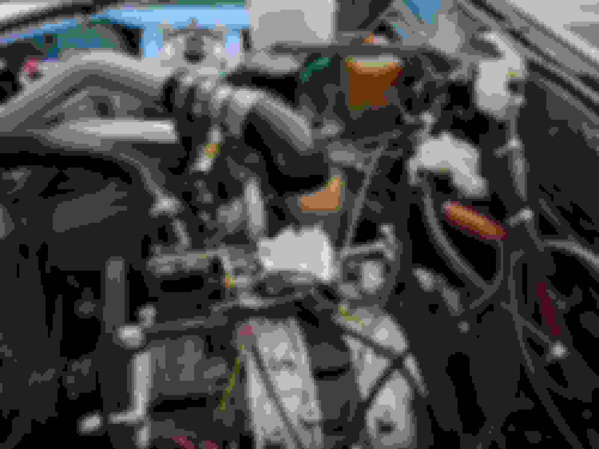
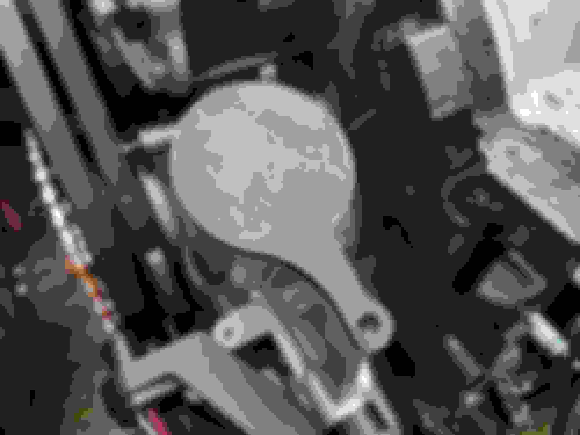
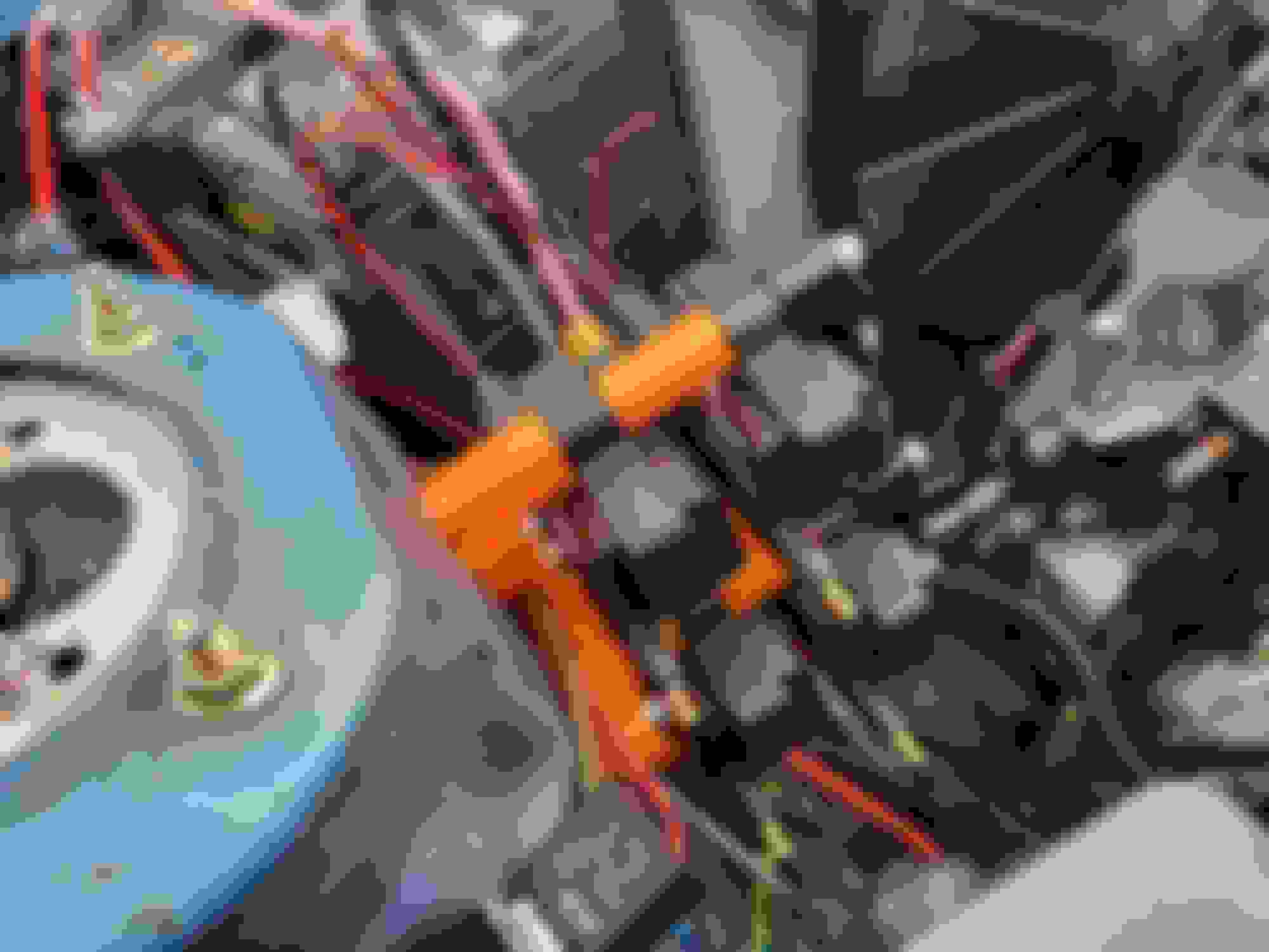
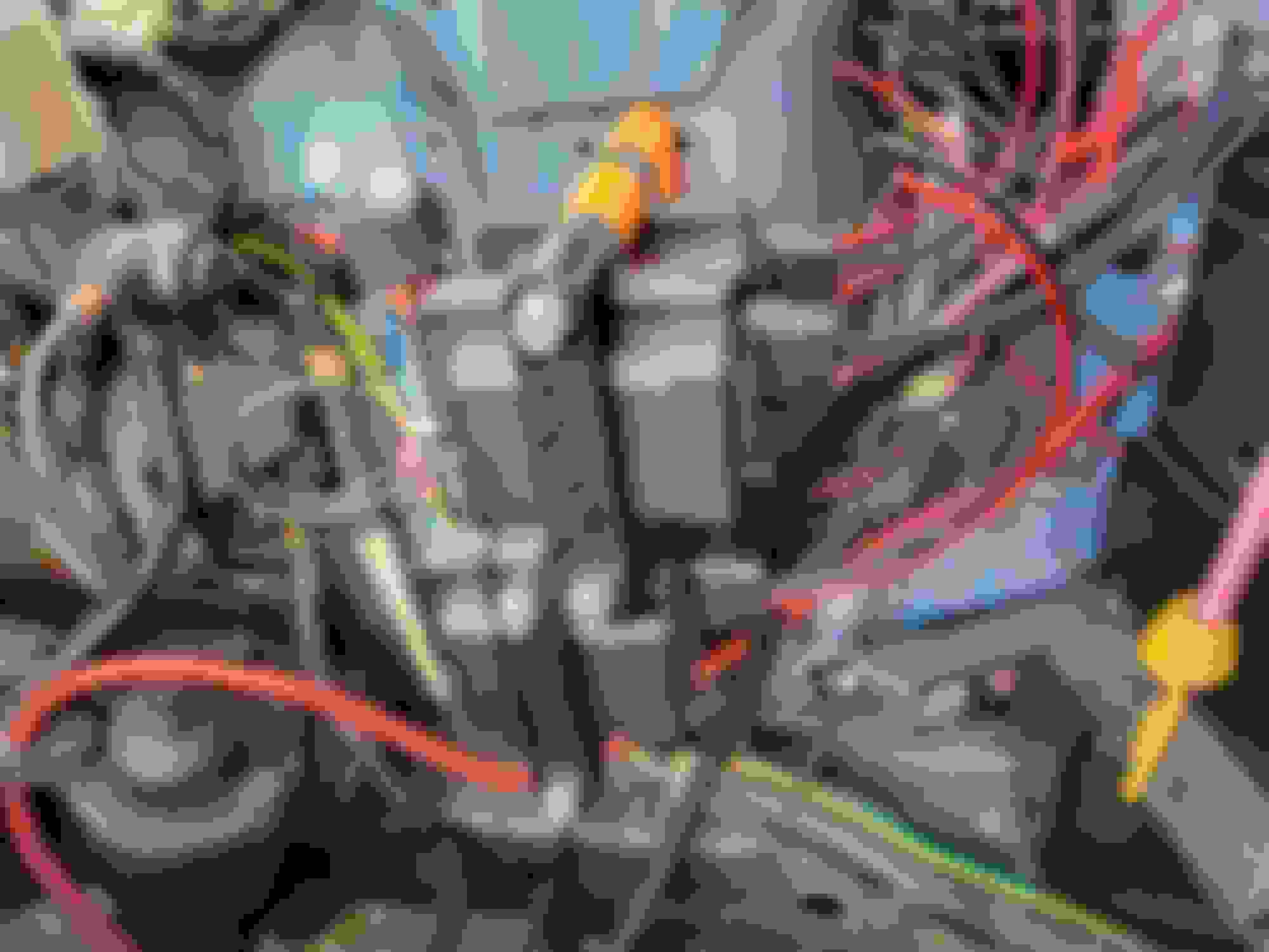
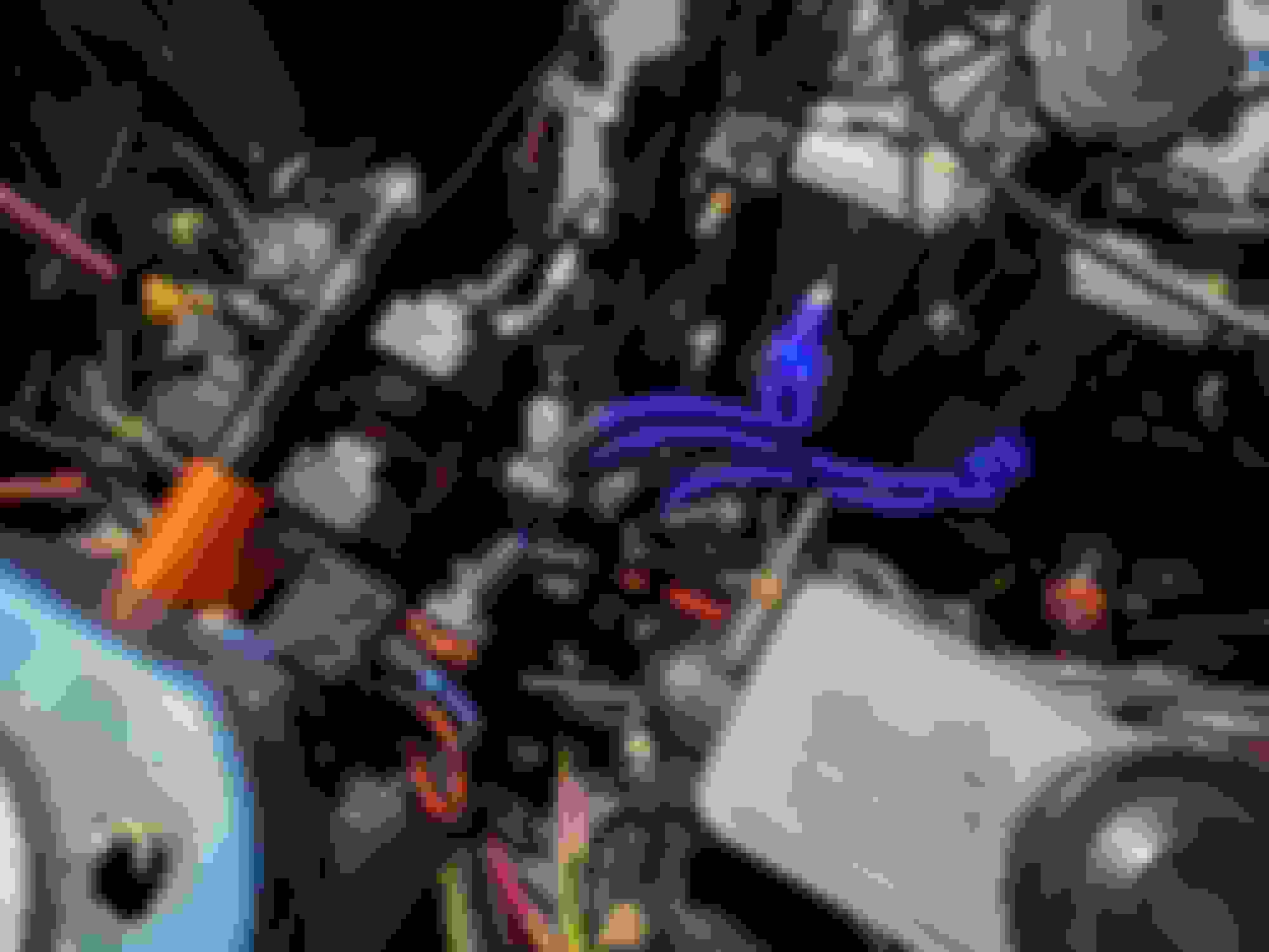
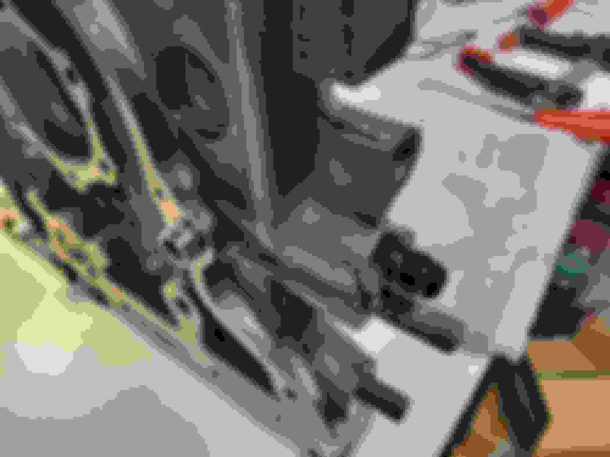
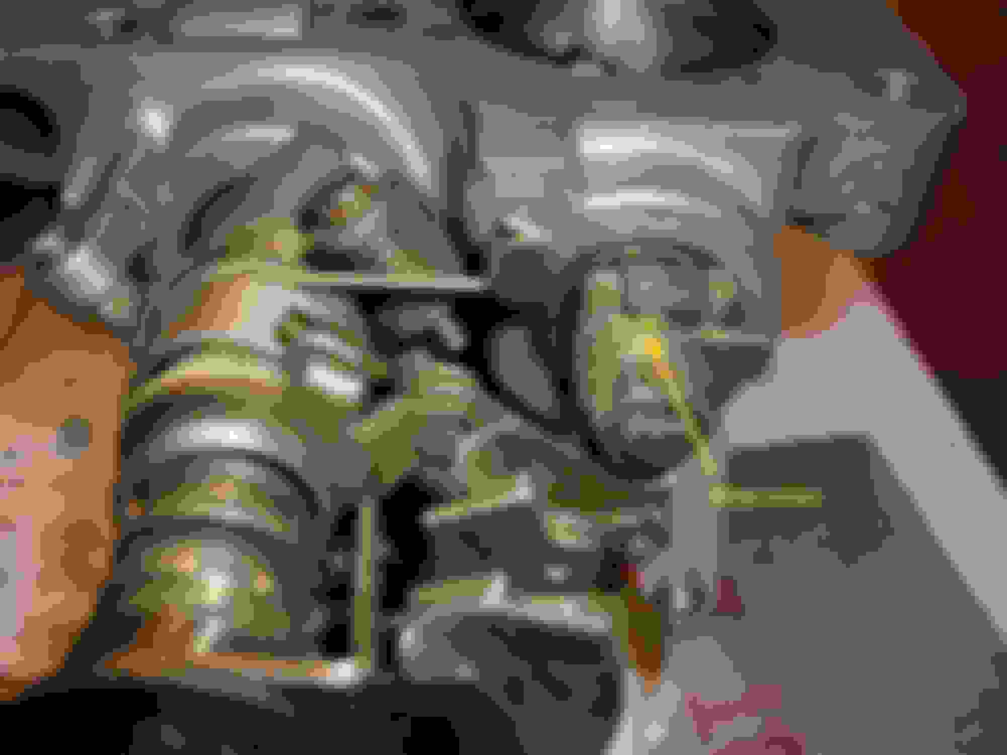
On the ignition front, I've begun working on a mounting solution for the IGN1As. I don't see a particularly good way to put them on the engine (I know 13B guys do, but the 12A has a little less space up there), so they are going on the drivers side strut tower. I'll be 3D printing the majority of the parts, although it's likely that it will have a metal baseplate as well for peace of mind. These new parts will hopefully be made from polycarbonate, but that relies on me being able to print the stuff. The printer modifications to allow that should also arrive later this week (the hotend has to be upwards of 300C!). Here's a few photos of the shenanigans.
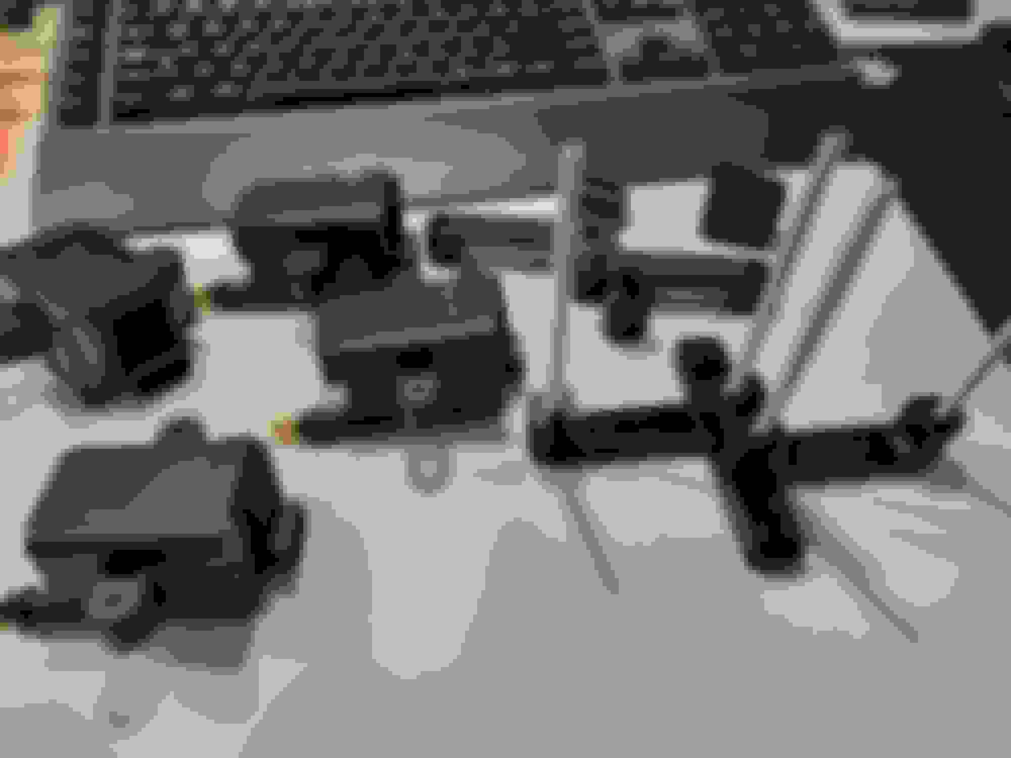
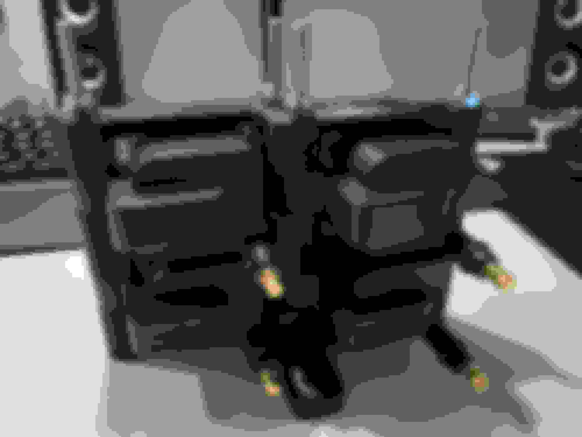
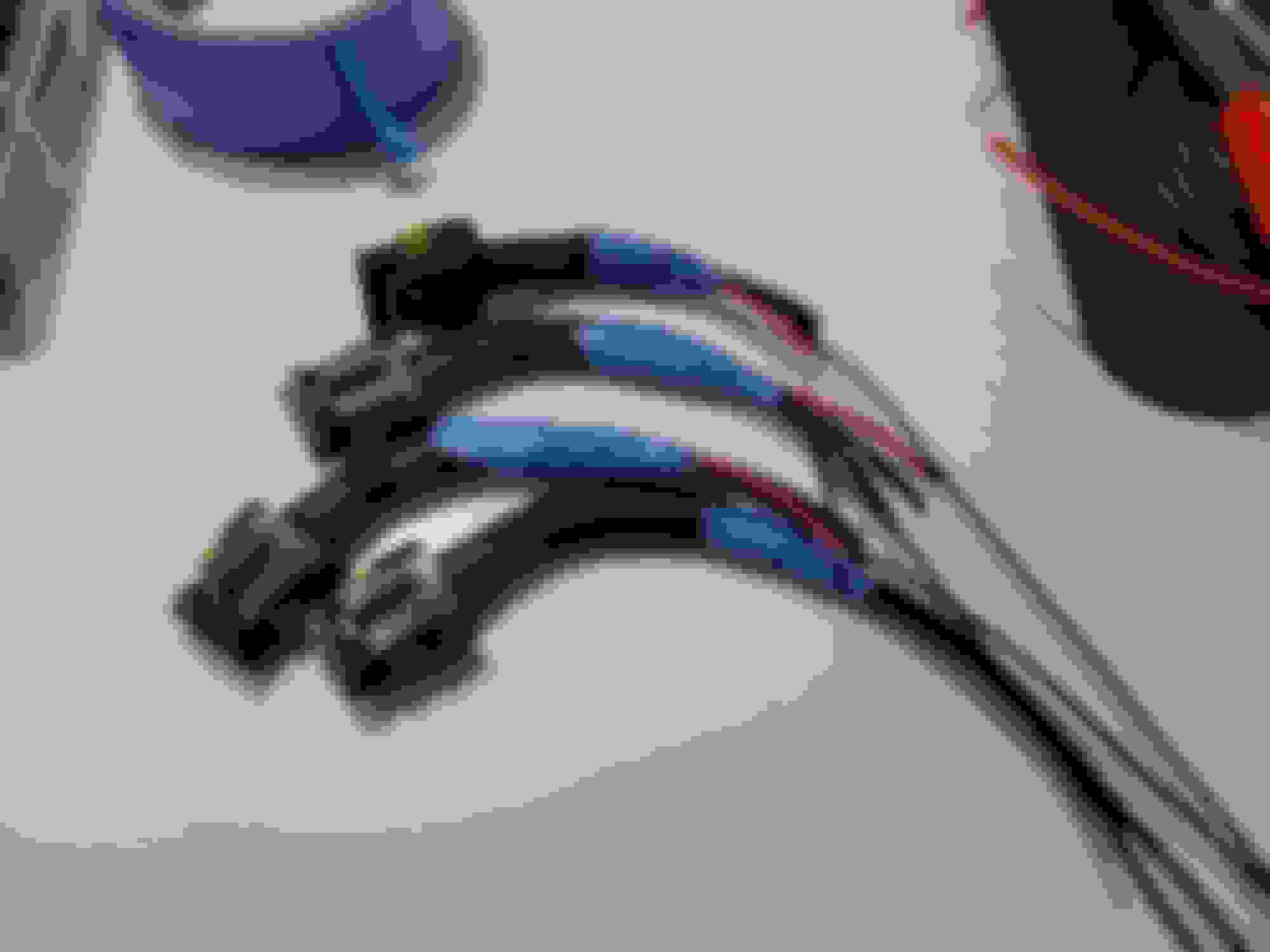
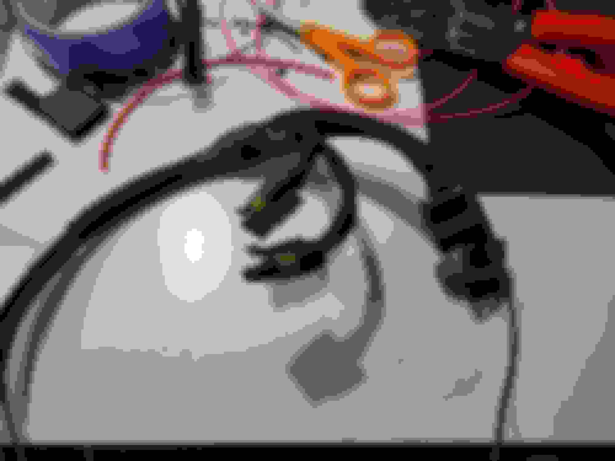
The design for the coil bracket is now finalized, although now I'm waiting for the new material to arrive (the orange is prototype material). While I'm waiting I've started on the coil harness. Realistically it's nearly done, I just need to decide where it's passing through the firewall so that I can add the last of the sheathing and terminate the ends. The TBI baseplates also arrived and look great, and the updated print finished successfully as well. Tomorrow I'm aiming to finish the wiring and get the new TBI body assembled. I suppose I need to make new plugs wires as well now that I think of it. In theory I have half a V8 Taylor set somewhere...
After getting the refreshed EFI setup back together I was able to install the new ignition system. Not much there besides wiring and whatnot, but it turned out well enough. Still waiting on a mosfet in order to get my tachometer working (now that it's triggered by the ECU), but that should be here tomorrow.
Unfortunately I've hit a small standstill. For whatever reason my ECU will not advance timing by the table I have input, and instead it keeps it locked at 0. This is true whether or not I have "fixed timing" enabled. I've gone through every spark menu I can find and I haven't found anything that seems to make a difference. I'm holding off on tuning any more until I get this worked out; no sense in tuning an engine locked to x degrees of timing. It's most likely some stupid thing I've overlooked, but I just don't see it.
Other than that it's running reasonably well at idle. Certainly not perfect, but again, I'm not tuning any further until I have timing control back.
Solved the ignition advance issue, and then my lambda sensor promptly died... What timing! [pun intended]
Now I'm waiting for a new sensor to arrive since tuning without it is rather impractical. I'll pull the current sensor out tomorrow and see if I can at least temporarily resurrect it while I wait for the replacement.
If only I was actually able to start the car now... Tried to see if my wideband sensor had miraculously recuperated (new one on the way) but I couldn't get the car started even with multiple attempts throughout the day. All that cranking sure put some fuel in the exhaust though, and man was it ever a loud backfire (I deflooded it a couple times). I have some new plugs I'll throw in tomorrow and see. The current set has been through a lot of idling, and very rich idling at that.
Well.... I've given up on this engine. It's just not worth chasing my tail trying to tune a setup with ~70psi of compression. It'll run and drive, but it hates to idle consistently and is really frickin' touchy. It's just not worth it.
So we're on to the next step. I've had two 12A kegs sitting as spares for some time, and a couple days ago I finally split them open to start my parts search. The first was a disappointment: the irons were okay, but the rear housing has some chrome flake. Then I tried to get the center iron off and the rotor was stuck to the e-shaft. Finally got it separated and it sure as heck spun a bearing, the housing is completely trashed too with flake across almost half of it. Thankfully the second engine actually yielded some useable parts. I got a good S3 rotating assembly from it and some more decent irons as back ups. The housings are usable but they have more chrome flake than is reasonable for this new engine. I do have new housings figured out though, so we're good there. So in theory I'll have a complete good condition 12A block in not too long. I'll likely try to reuse my current irons depending on wear, but we'll see. I have more if they are required.
As far as modifications go, this will be a "medium-low" power build. Porting will be Pineapple medium street ports, it'll be running solid one pieces dowels with the external oil loop, and likely clearanced rotors and milled down hardened 13B stationary gears. The gears aren't certain yet though, as I don't intend to turn it past 7500 or so. Multiwindow bearings will happen regardless. I already have some S3 oil pumps, and if I recall correctly that's the largest that will fit a 12A; oil pressure will be bumped up as well. This is still a street car, and hopefully a daily at that. The goal is a reliable 250-300whp, but we'll see as we go. I don't plan on exceeding 14psi, and it'll likely be closer to 10psi most of the time. The same turbo setup and whatnot will remain, and I'm also trying to find a SouthBend clutch for it, but we'll see on that. This build will progress rather slowly due to time and financial constraints, but it'll get done eventually. Goal is by early summer, and I feel like that's a pretty safe target.
If you can't tell I'm just a bit fed up with this car . While it's still down I'll also do a few other little things to it, one being that I have another rear end to swap in that doesn't have any slop in the spider gears (yes, I do not have an LSD). I'll also be taking another crack at the rainwater leaks that have managed worked their way back in. The oil cooler also has a leak somewhere by the lines that I need to figure out, so I'll likely make new lines and also have the cooler cleaned properly as well.
For now though there isn't a whole lot to do. Engine parts need cleaning and I'll work on that sometime here. I think that's about it. Cheers.
I�m sorry to hear about your setback. Was looking to seeing your work at meets in the northwest this year
In the grand scheme of things it's not a terrible setback, and it does give me a good reason to build a solid 12A, so I'm looking forward to that. Today I stopped by Pineapple Racing and talked with Rob for a while (awesome guy by the way). Picked up a couple porting templates and figured out what else will be needed to build a solid everyday 12AT setup. Certainly looking forward to the new version of this car. The fresh 12A housings arrive this Thursday from out of state, so I'll get to porting those with the spare time I have in the next couple weeks. Funny enough, my self-designed intake ports from last go around are actually larger than a Pineapple medium port, didn't expect that. The Pineapple exhaust on the other hand is a lot larger than what's in the car, being essentially the same as the narrowed T2 template I have.
I sure hope I can still make some PNW events this year (maybe the Atkins event won't get cancelled this time). Goal is to be done by early summer. Definitely looking forward to seeing your car out there too.
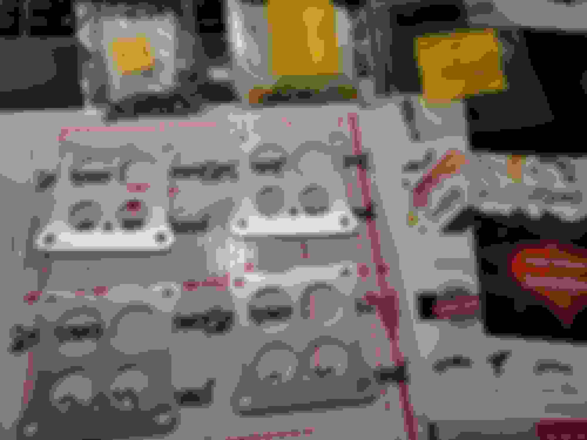
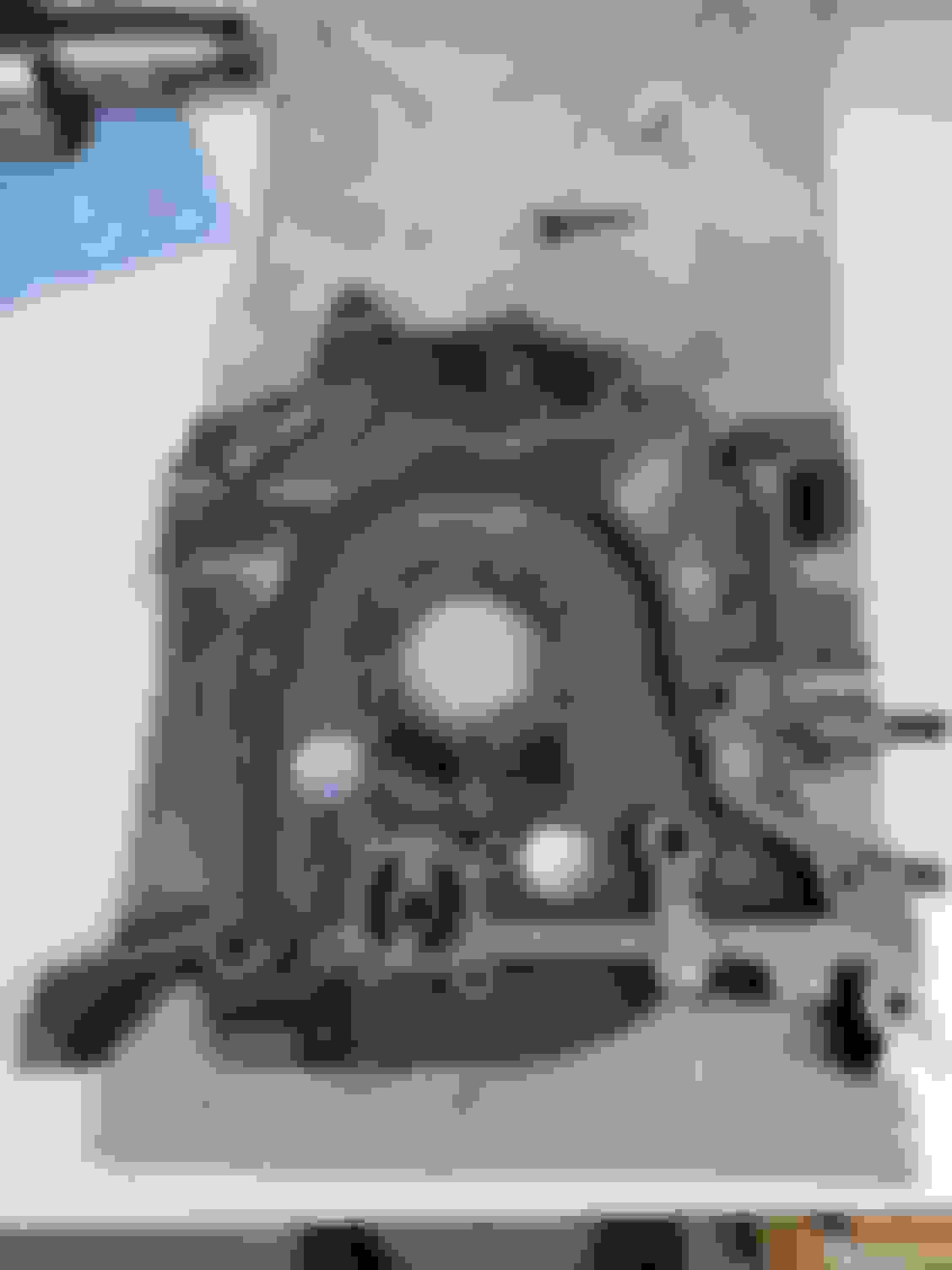
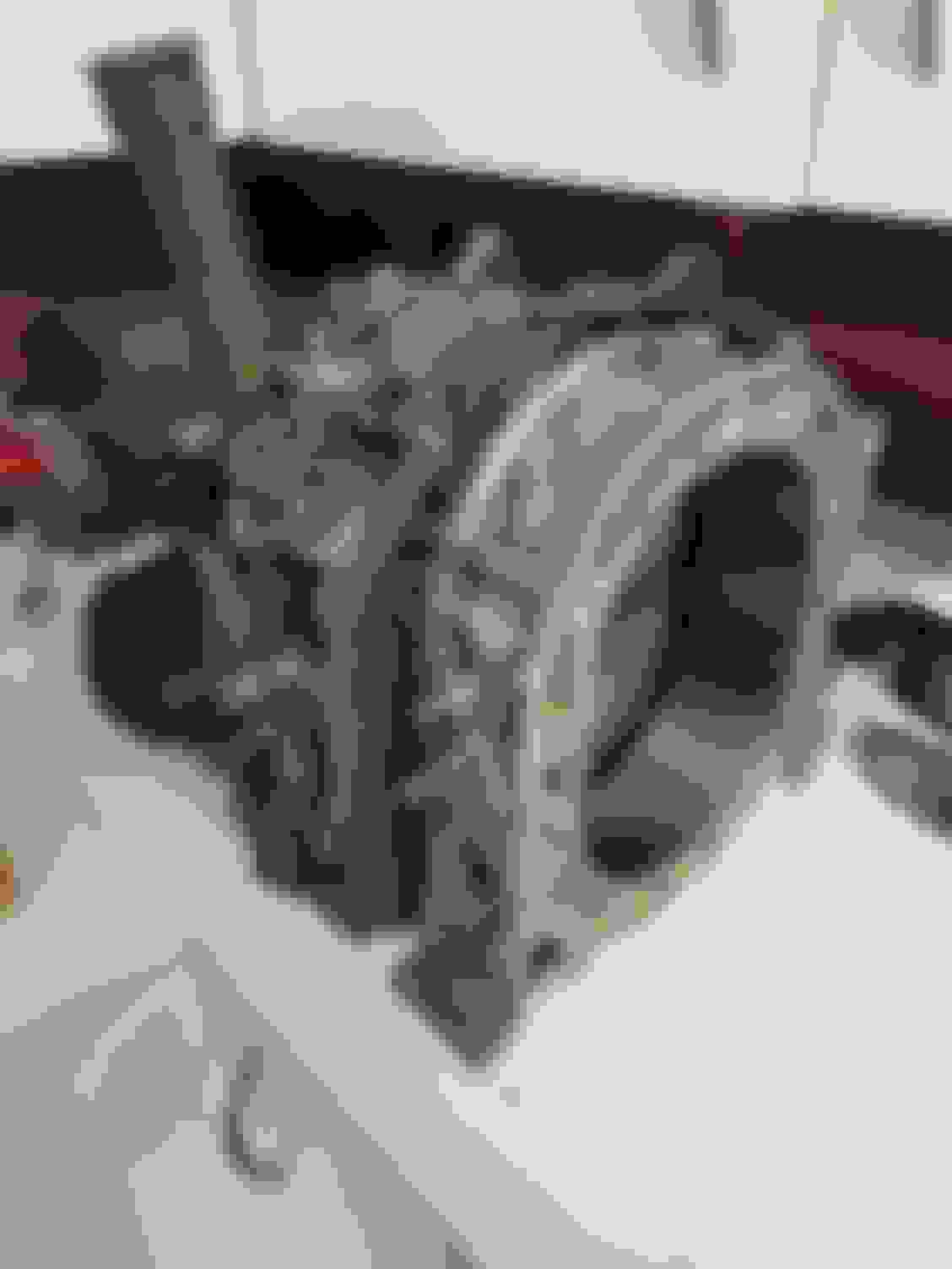
The engine block is beginning to make some progress. The set of 12A housings arrived Thursday and they are looking stellar. Zero chrome flake, and the light chatter that shows in one of the photos is essentially invisible in person. I certainly feel lucky to have these given 12A housing availability these days. Here's a couple photos:
So far I've cleaned all the irons and one housing. Not to the level of "paint, install, and go" but it's close. It's more than good enough for porting which is what I was aiming for. As I've mentioned above I'm using Pineapple templates this time around and seeing the exhaust template on the housing really conveys how large it is. It's now evident that their intake does open a tad earlier than my old porting as well.
Sometime next week I'll get the final housing prepped and begin porting. That'll probably take a couple weeks of free time and then it'll be on to paint - planning on the same aluminum/black color scheme as last time. I also need to draw up an oil pan baffle and a new ACV plate that'll work with my turbo's space constraints, so that'll happen at some point here too. A couple more photos to wrap this up:
A couple months later and it's finally time to resume work on the SA. Yesterday I began porting the irons and as of now I have two and a half intake ports done. At the rate I'm going here I expect to have the engine fully built in about six to eight weeks from now, and that's pretty well in line with my original goal. Not a whole lot to share yet, but here are some photos of one of the finished ports as well as a template trace showing the difference from stock.
Exhaust ports are done , and man alive do I hate exhaust porting. Template is based on a Pineapple medium port with some suggested timing changes from Rob and a couple profile tweaks by myself. Admittedly they are rather, large...
Technically the exhaust porting was done last week, but I'm posting it now because I forgot to take pictures.
Today I also cleaned up the rotors a little bit to have them ready for face clearancing hopefully next week. I had planned on getting that done last week but Pineapple was (and is) out of the RX8 stationary gears. Ended up ordering some on Tuesday and hopefully those will be here soon. Once they arrive I'll get the rotors and gears done at the same time.
Other than that not much has happened. Next up is porting the stationary gear oil feeds to match the irons, as well as porting the oil pump gallery and tapping for the external oil loop. That will happen sometime late next week I hope.
Still trying to decide on whether to run the external oil loop line to the top of the iron or the side if anyone wants to chime in. Top is in the way of less stuff, but it only removes one of the two hard 90's. The side takes care of both 90's, but would block any future AC or power steering install (and I want to put AC in this thing some day). Opinions welcome.
wow. i guess i haven't looked in in a while. sorry to hear about your setback, but think of it as the price for progress. i know you'll get it done. one thing i'll mention is the oil pump (because you mentioned it earlier). remember the SE pump bolts on and has more volume. that said, i also know Peejay mentions cavitation with the SE pump at high RPM, so as with most things, there are pluses and minuses. whether or not it's something you're interested in or if it's worth trying to find one, i'll leave up to you,
i like the ports. i especially like what you did with the exhausts.
Originally Posted by Benjamin4456
...and I'm also trying to find a SouthBend clutch for it, but we'll see on that.
Regarding the oil pump, I tend to side on the 17mm pump camp based on what I've seen and read. Conveniently I already have a number of them around so no changes were needed there - the 17mm came in all first gen engines (12A and 13B) from 1983 and on, not just the SE, so my most of my 12A blocks already had them. My SA's "original" engine, which is what I am using as the core for this build, was actually an 83 block someone swapped in. The engine I had built previously and cracked an iron on was an 82 but someone had swapped the 17mm pump in before me. 17mm pumps every which way .
As for the clutch, I've actually changed my mind on going with a SouthBend. Originally I wanted to find one as they are known for great quality stuff while also not costing an arm and a leg. What ended up changing my mind was the transmission strength compared to the clutch capacity - SouthBend's stage 1 clutch holds 304ft-lbs and the stage 2 hold 376ft-lbs according to the rep I talked to. Both of those numbers are far beyond what this transmission will tolerate, and I'd much rather slip a clutch than blow a transmission, especially since this car will resume duty as primary transportation at some point. Instead I'm opting go for an Exedy 10806 which is rated for 196ft-lbs at the tire. If I was making that torque at 7500rpm that'd be ~280HP which I'm fine with. In theory this block will hold north of 350HP with a good tune, but I don't intend to run it that high. If ever I do decide to go for more power the transmission and rear end will need to be dealt with anyway, at which a new clutch will be required regardless. So in this instance, I think the $80 extra for the SouthBend can be better spent elsewhere.
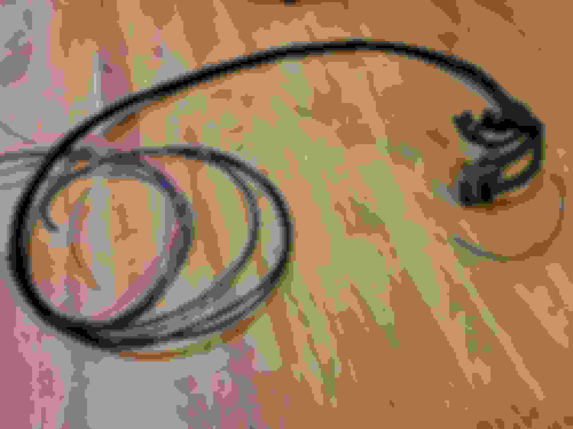
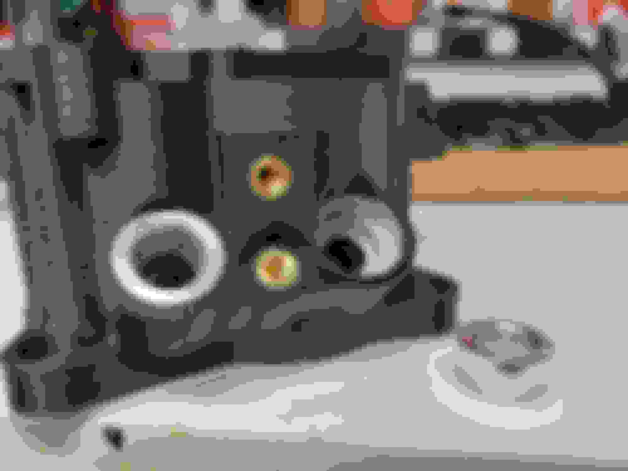
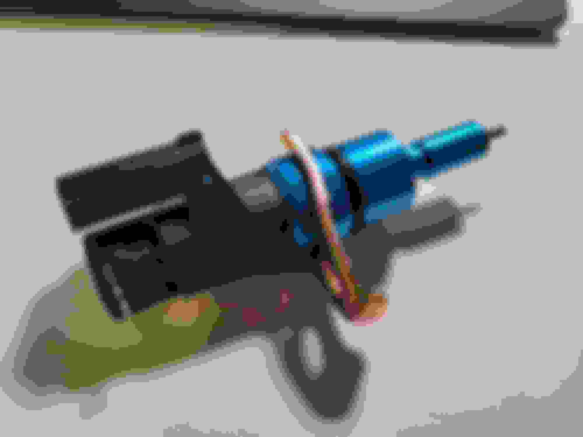
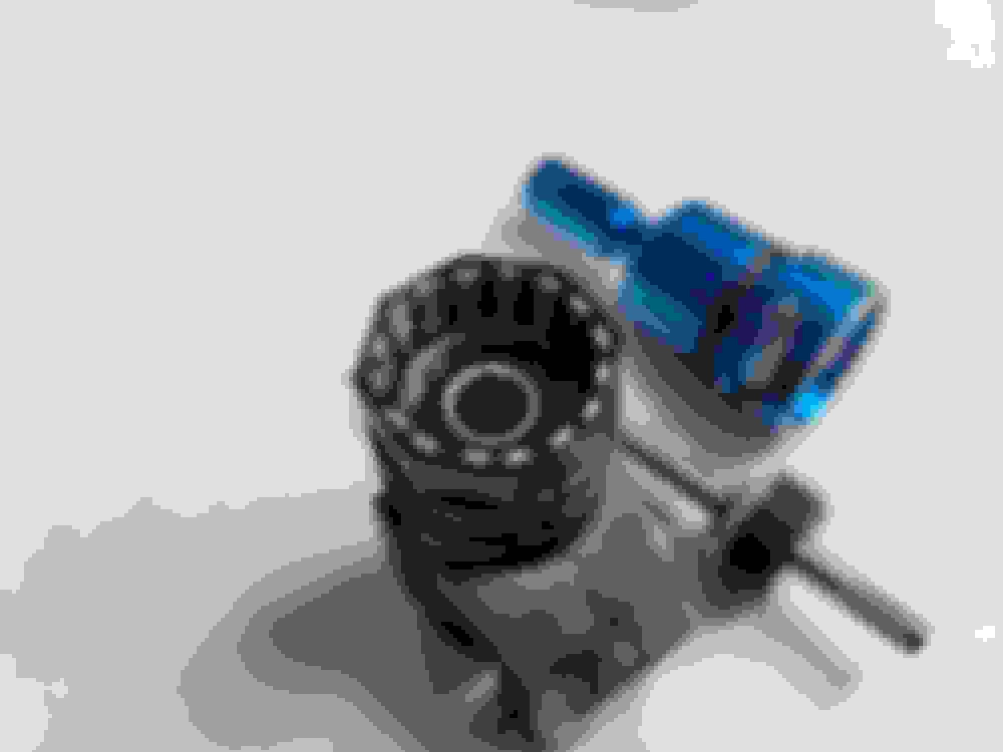
On a different subject, I'm continuing to look into the addition of a vehicle speed sensor to the car. I had wanted to do this before but hadn't seen a good option until a recent thread on the subject led me to revisit the topic. I then did a little looking and discovered that Ford used a VSS throughout the 90s that passes the speedometer cable through the sensor, which is the perfect solution (in my mind) for maintaining the factory speedo while adding a VSS. In this case the part I am attempting to use is a Standard Motor Products part number SC46 (the SC46T is equivalent). An SC37 is the same sensor but with the pass-through blocked off.
The goal is to dismantle the sensor and see if it can be modified with a new 3D printed housing to fit in-between the transmission and speedo cable for our cars. While there are existing aftermarket sensors similar to this (with the wrong threads however), the reason for using this one is that it can be had for less than 20 bucks and can be sourced without too much trouble. I was able to pick one up today and it looks promising, but I won't know until I manage to crack it open. Until then it's anyone's guess as to whether it'll work. One thing I do know is that it outputs an AC signal, but that's not difficult to translate to a square wave that the ECU will understand. Realistically I don't really need a VSS for my setup, it's just another thing to play with at the moment. To close off this post, here's a photo of the sensor.
VSS� there is a vehicle speed sensor that feeds from the speedometer. I believe it�s a brown and yellow wire that goes to the cruise module. I removed all the cruise wiring but left the speed signal as a pigtail with shrink tube on the end accessible. In case I can implement it in the future
I don't know that the VSS exists in the SA cluster - did any S1s have cruise control? That's what it's intended for.
It's very definitely in S3s - we tapped into it for speed data on a race data recorder on a friends GSL-SE. I believe the S2s use the same cruise setup. The wire can be found in the dash cluster harness and at the CC module under the rear bins, which is where we tapped in, since the data recorder was back there as well.
You can check wiring diagrams on mine or Sgt. Fox's websites to be certain.
have to follow up. Is the signal from the dash a hall effect or reluctor? I�m still not clear on the two. I think the signal is a Hall effect with a sine wave. If I recall the speedometer cable is 1024rpm/60mph Not clear if that translates to in pulse per mile.
Originally Posted by Frankenrex
I don't know that the VSS exists in the SA cluster - did any S1s have cruise control? That's what it's intended for.
It's very definitely in S3s - we tapped into it for speed data on a race data recorder on a friends GSL-SE. I believe the S2s use the same cruise setup. The wire can be found in the dash cluster harness and at the CC module under the rear bins, which is where we tapped in, since the data recorder was back there as well.
You can check wiring diagrams on mine or Sgt. Fox's websites to be certain.
have to follow up. Is the signal from the dash a hall effect or reluctor? I�m still not clear on the two. I think the signal is a Hall effect with a sine wave. If I recall the speedometer cable is 1024rpm/60mph Not clear if that translates to in pulse per mile.
A reluctor wheel configuration would produce an AC sine wave output (like in the distributor). Hall effect on the other hand is digital. I'm honestly not sure which it is since I have yet to encounter this system on my dash, although my guess would be reluctor. I had the cluster apart for repairs not long ago and I can't remember anything electrical being connected to the speedometer input, although I could be wrong. It is a weird cluster - 1980 configuration but with the 130mph speedo. Not swapped either unless they made a white/green speedo in years other than 1979 and 1980.
Edit: Just checked some photos from when I had it apart, definitely no sensor doohickeys on the speedo/odometer input.
Last edited by Benjamin4456; Apr 24, 2022 at 11:42 PM.
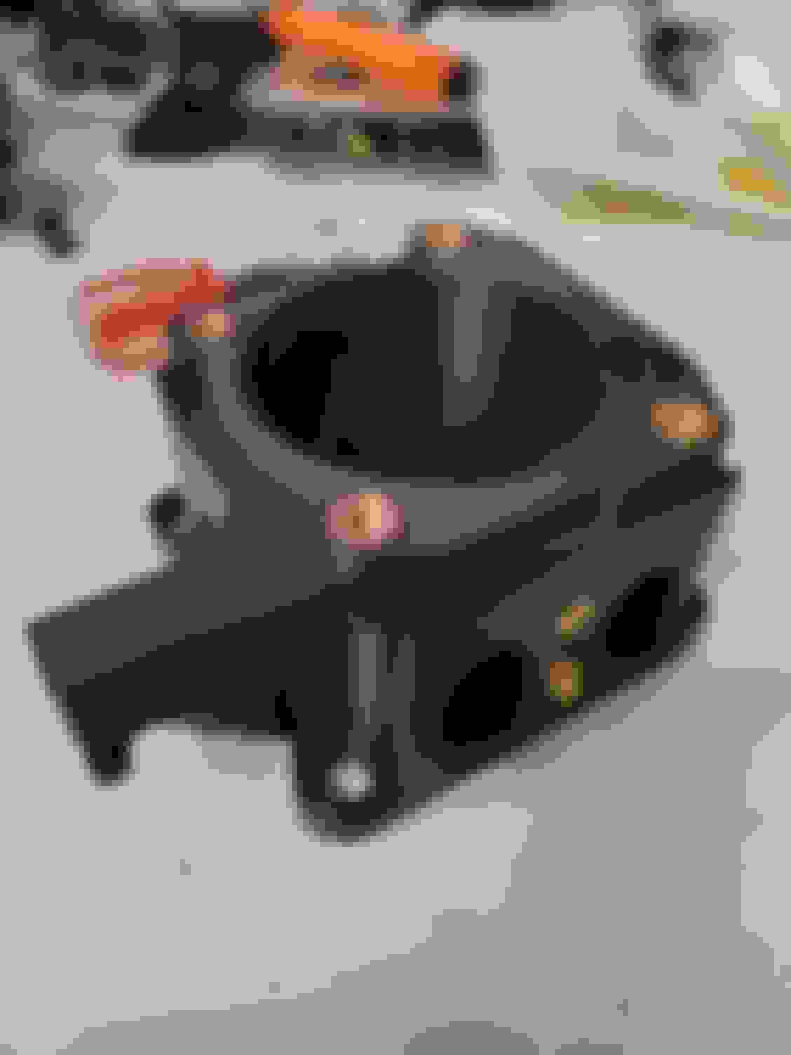
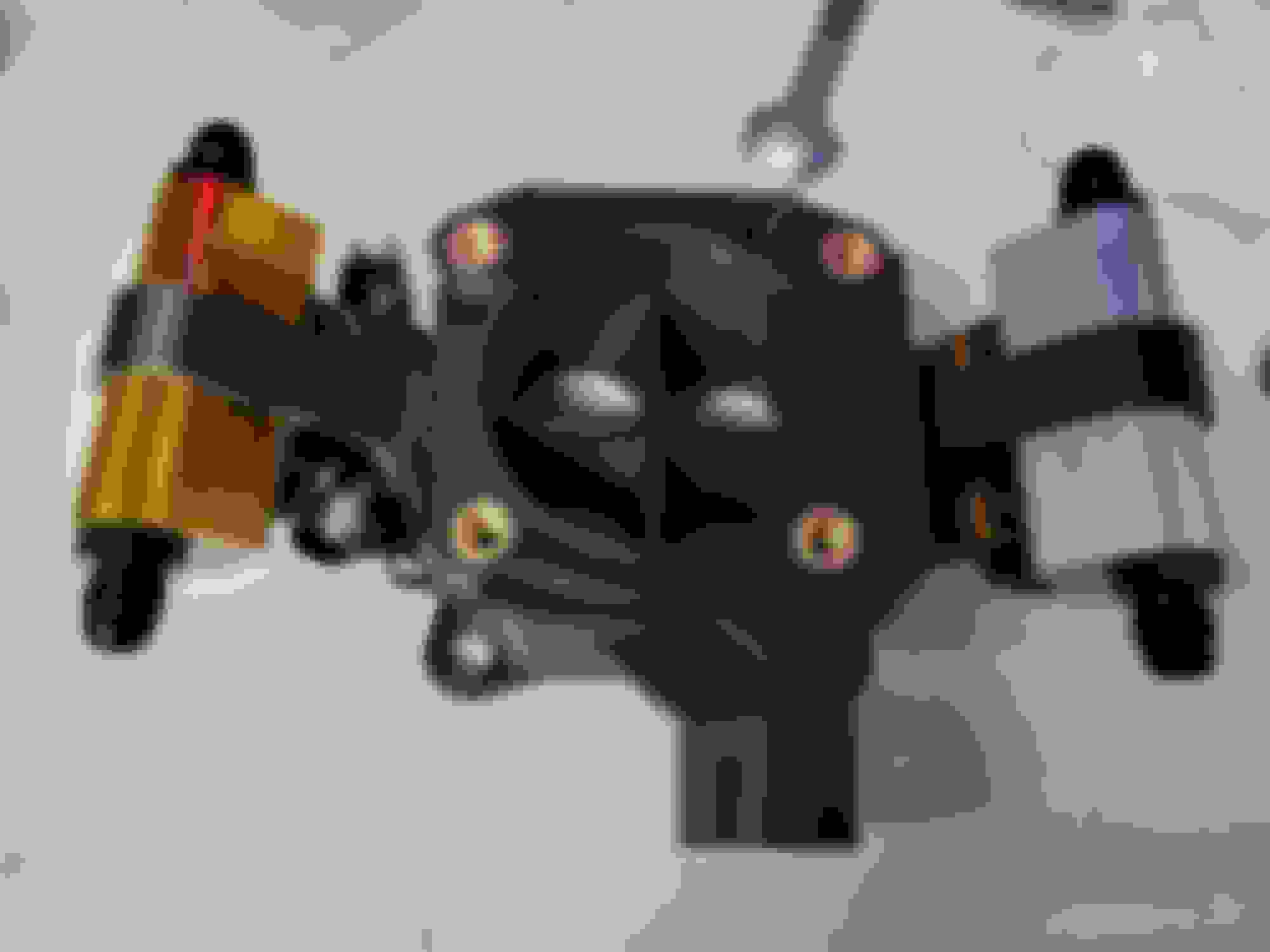
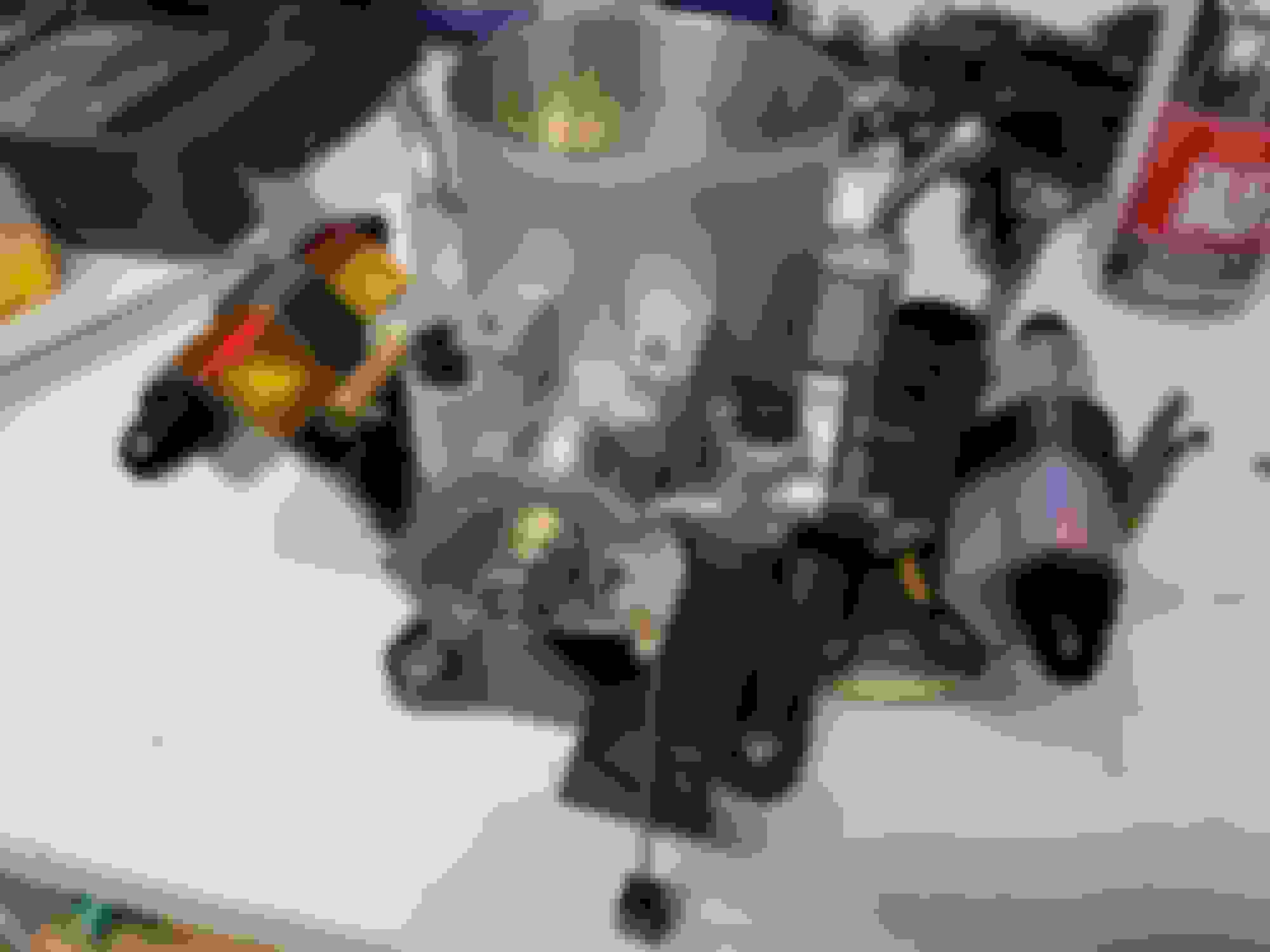
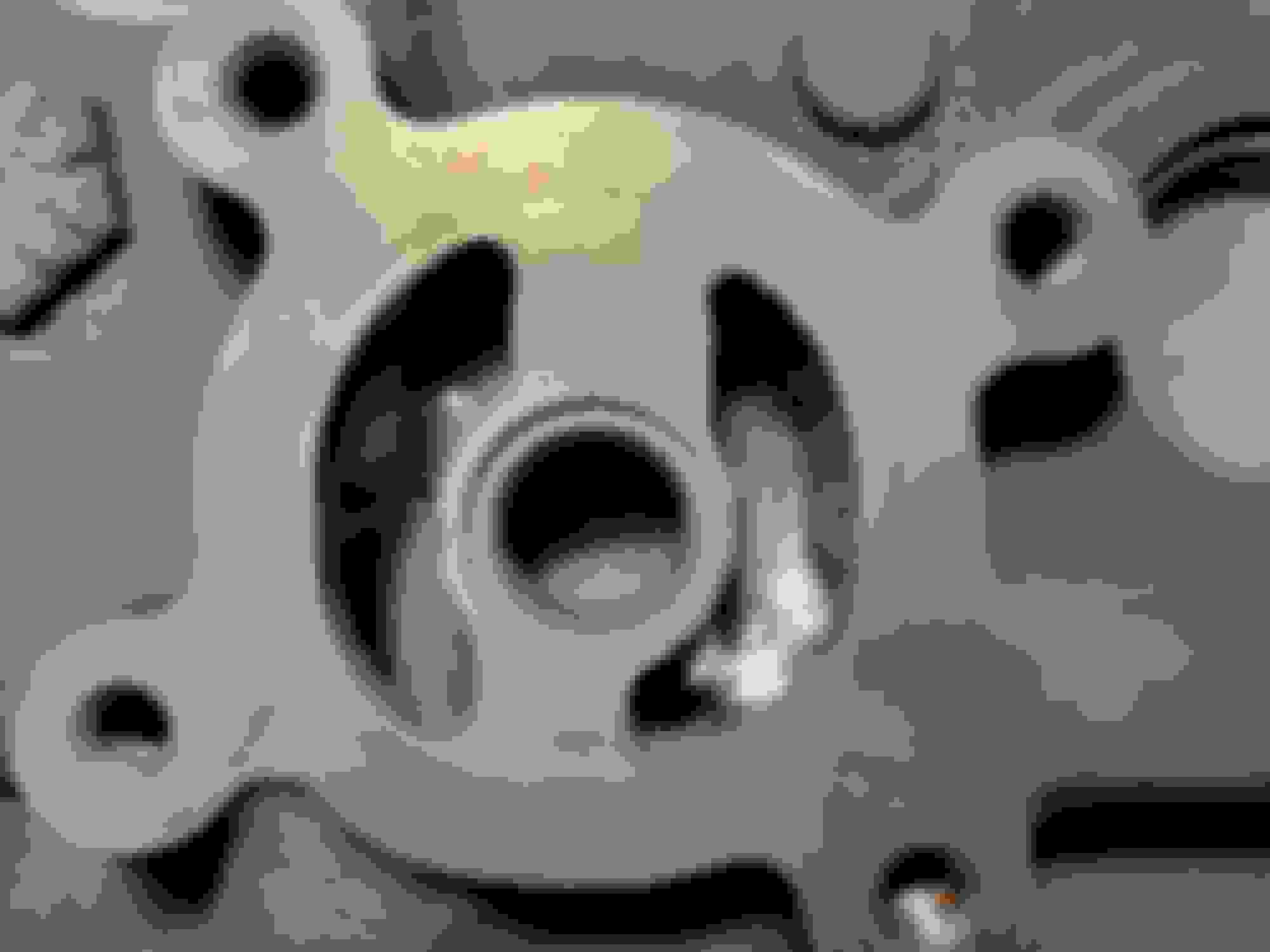
On a VSS related note, my first DIY idea has failed. Unfortunately it's a bit difficult to repurpose a sensor where the coil/pickup is cast into the housing:
I have another, better, and even more convoluted idea as well (making my own VSS module from scratch), although I'm going to hold off on any more VSS experiments until the car is actually running and driving. It's also entirely possible that I'll just end up putting a trigger wheel on the differential flange and doing it that way, who knows.
Additionally, tonight I began porting the oil pump gallery, and having now looked at it in detail one really gets an idea how terrible the sharp edges are (particularly on the inlet). To my dismay I got my primary burr caught and bent it so I'll be waiting on more porting until the replacement arrives - it's a pretty small space you're dealing with in there and it's darn easy to wedge a burr. I think I like oil pump porting even less than exhaust porting, maybe...
have to follow up. Is the signal from the dash a hall effect or reluctor? I’m still not clear on the two. I think the signal is a Hall effect with a sine wave. If I recall the speedometer cable is 1024rpm/60mph Not clear if that translates to in pulse per mile.
I *think* it's a Hall-effect, which is a pulsed square wave, but it's been a bit more than a minute since we did it, and he no longer has the car or the data logger.
One thing that may help is that the speedo mechanisms themselves may be able to be swapped. As I recall, all first-gen speedos use the same RPM/mile on the speedo cable, so theoretically the mechanism may be swapped between dashes. Of course, the sweep would have to match. 85 MPH vs 130 MPH faces might be a problem, as an example, so it might get complicated.
Looking at the '84 wiring diagram, the VSS is a BR (black/red stripe, I think) wire on connector C-01, and is used for Cruise Control, the speed-sensitive power steering, A/T control, and the ECU.
The '81 diagram shows a separate "speed pulse generator", connector B-29, a 3-pin connector with BL, BR, and B (black/light-blue, black/red, and black) wires. B-29 is under the brake master cylinder, and appears to go to the rear/mid of the transmission, so you may be able to use that instead?
Unfortunately I don't have a copy of an S2 Factory Service Manual, at least in digital, to check the transmission section. I think I have a paper copy, maybe.
It does not show a speed sensor in the cluster, so that's '84-85 only for certain.
'82 shows similar, but the connector B-29 is a single BR and X-05 and X-06 (both B, the ground wire) under the dash.
'83 also shows similar, but only X-05 (BR) and X-06 (B) under the dash.
X-05 and X-06 are the two large round connectors for the gauge cluster. Interestingly, both '82 and '83 show a BR in the same position on X-05, so I'm not sure what that single B-29 is about on '82.
edit: I'm really vexed that there's no S2 FSM online. Enough that I may buy one and scan it, if I don't already have one.
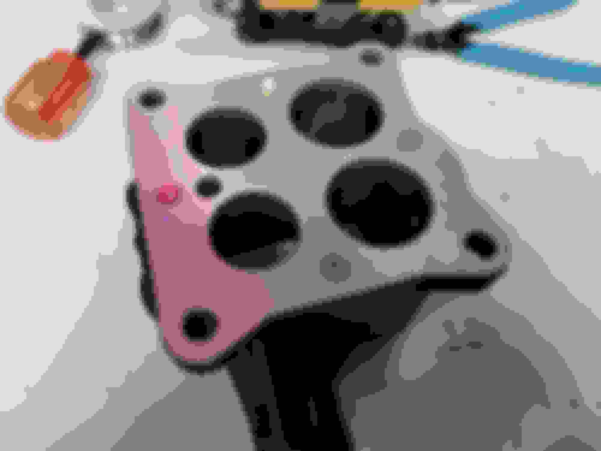
Drilled and tapped for the oil loop line yesterday. Decided to use the side of the iron since it has more meat and cuts out an extra 90 - I'll figure out a solution to mounting the AC whenever the time comes.
Since I've opted to use the side of the iron for the loop fitting, I've decided I'll also relocate the oil cooler supply from the front cover to the front iron. That cuts out another couple 90s and lets me put a hollow dowel in the front cover port to help retain the o-ring and reduce leaks at high pressure. The dowel isn't really needed, it's just a peace of mind thing that I might as well do. The only thing to figure out yet is machining a step in the boss so that the dowel can't fall down, although even if it did it would only block the oil pressure bypass since the main feed will exit the side of the iron.
Unfortunately the iron is too tall for my drill press and so I had to do the drilling by hand. That resulted in a not quite perfectly straight hole which then required some corrective surgery to make sure it all sealed up. I also drilled the hole a tad larger than ideal, but there's still plenty of thread for the fitting to hold on with. As of yet I've only done the oil loop fitting, not the new main oil outlet. I've ordered the proper size bit for the next hole. Not my best work, and admittedly I was hesitant to share photos, but it'll be more than sufficient. Photos below.


 . It's always fun to have a project that others enjoy. I don't have any new photos just yet, but I'll try to get some in the nearish future. Unfortunately it's been raining a lot (good ole Oregon) so it's not exactly ideal photo weather. That is one nice thing about EFI though - I can sit inside the car to tune it
  .
.