Something completely different - a very long term tube chassis project
 11-02-20, 06:47 PM
#76
spoon!
Thread Starter
The Amazing Mumford (link)! Gets roll center where I want it (below where there's any chassis members) and has very little roll center migration relative to the CG. A little extra complexity compared to a Watts but what the heck.

The following 2 users liked this post by Kenku:
gracer7-rx7 (11-14-20),
mustanghammer (11-02-20)
11-02-20, 07:27 PM
#78
spoon!
Thread Starter
So I've got things, at static ride height, with roll center at about ground level and moving with the chassis almost perfectly across the whole stroke... rear about 2 inches above ground and moving with the chassis across most of the stroke... need to redo the rear chassis so there's mount points for the Mumford (and make sure the QC clears) but that's not too complicated.
I wish I could have less scrub on the front; took the tradeoff for a bit more scrub in exchange for a lot less kingpin inclination. 7" wheels and 10" wide tires means not too much can be done.
11-02-20, 09:02 PM
#79
Are you moving the car to GT2 or staying in GT3? Never mind.....reread your post = 7" wheel with 10" tires. It seems like the straight sidewall radial slicks are getting more popular. They are narrower.
Last edited by mustanghammer; 11-02-20 at 09:05 PM.
11-03-20, 06:45 AM
#80
spoon!
Thread Starter
I have a pipe dream of GT2 but it's a very quixotic sort of thing. Talking to Pete Peterson at the runoffs who's running a V6 Celica in GT2... the traditional tube chassis cars in the class are basically having the hurdles of having to run very aggressive engines (in RX-7 case a peripheral 20B with a lot of development) and find tires soft enough somehow (most made for the relevant sizes are made for cars a thousand pounds heavier) and run the whole race at qualifying pace, and not make any mistakes. And then on a fast track there's not even that chance really. He had a very trick car and has been doing this for decades, and qualified 5 seconds off pole.
It'd be really really cool to try but the extra costs...
11-03-20, 05:06 PM
#81
Well when I saw "10 inch wide tires" I thought you might be trying American Racer tires. If you run them, you get to use a 10" wide wheel. Charlie Clark as run them on his EP RX7. Not terrible and really cheap....
It seems like traditional GT2 cars are punished by the current rule set. I remember when the Patton Sunbeam Tiger was a front runner. Same with Pete Peterson. The Sunbeam Tiger with the tiger strips was originally an autox car that ran in B Prepared and won some championships. Then the original owner went club racing.
It seems like traditional GT2 cars are punished by the current rule set. I remember when the Patton Sunbeam Tiger was a front runner. Same with Pete Peterson. The Sunbeam Tiger with the tiger strips was originally an autox car that ran in B Prepared and won some championships. Then the original owner went club racing.
11-03-20, 07:17 PM
#82
spoon!
Thread Starter
GT2 is ... things have shifted because it's become a huge catch-all class. Right now the big dominant things are built to what used to basically be the World Challenge GT class rules, with some sprinkling of TA2 cars... all of which have more power and broader powerbands than the "traditional" GT2 cars. I understand why it happened but as a fan of tube chassis small bore cars it kinda sucks.
11-03-20, 09:23 PM
#83
Yep. Not allot of super-spendy tube frame, small bore high HP cars with laying around. Certainly not enough of them to maintain a class. As I recall it started going a little south when the Panoz race cars were added (although they were not supposed to be competitive).
They...the CRB...was pushing something similar when they investigated adding SMG (a spec mustang class - S197 chassis powered by a 4.6L V8) to STU. Which is after A Sedan, a class where SMGs would seem to fit, successfully lobbied (with help of the CRB Chair) to keep them out of their class. Like I really wanted to go door to door with a 3200lb car that towers over me.
Anyway, sorry for the thread digression. Keep posing up more cool parts I could maybe fabricate.
The following users liked this post:
gracer7-rx7 (11-14-20)
11-04-20, 09:12 AM
#84
spoon!
Thread Starter
I understand why GT2 shifted after there's no new supply of ex-IMSA GTU tube chassis cars, but I don't have to like it. But for my sanity I really should acknowledge it.
I think today's project is going to be to start detail design of the front uprights. I'm thinking bolted upper pivot point with shims - so camber can be adjusted quickly, precisely and repeatably without moving the pivot point and affecting KPI and so on. Also need to redesign the rear of the chassis a little to fit the Mumford link and quick change but that honestly doesn't have much in the way of greater implications.
At some point I need/want to start figuring out ducting and wing mounting too. Talked to the friend who owns the molds for the bodywork I want to base off of at the runoffs and probably going to pull a tooling copy of the nose (IE really heavy because it's just for making a bodywork plug) out of his molds and redo the rest of the arches myself.
 Mostly that setup...
11-09-20, 06:40 PM
Mostly that setup...
11-09-20, 06:40 PM
#85
spoon!
Thread Starter
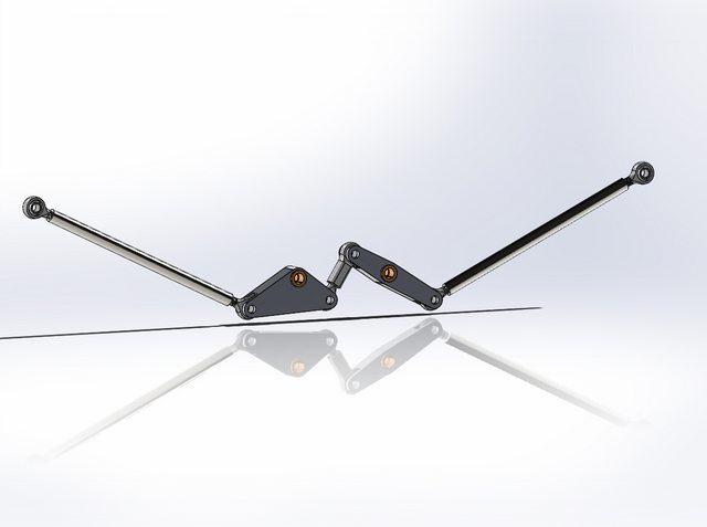
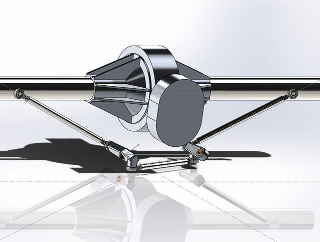
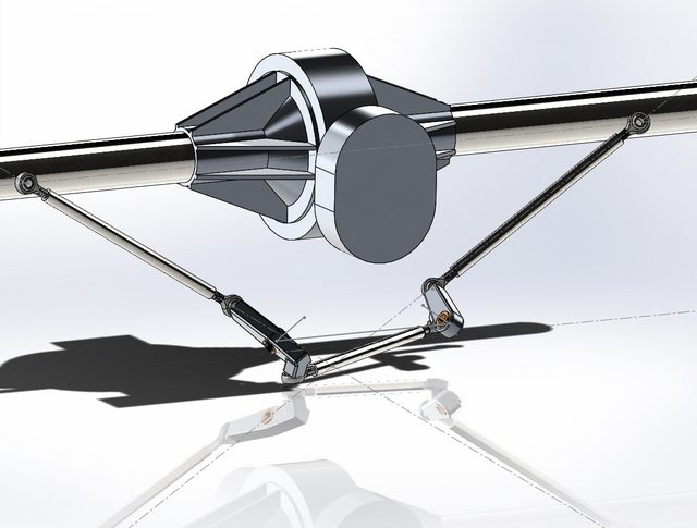
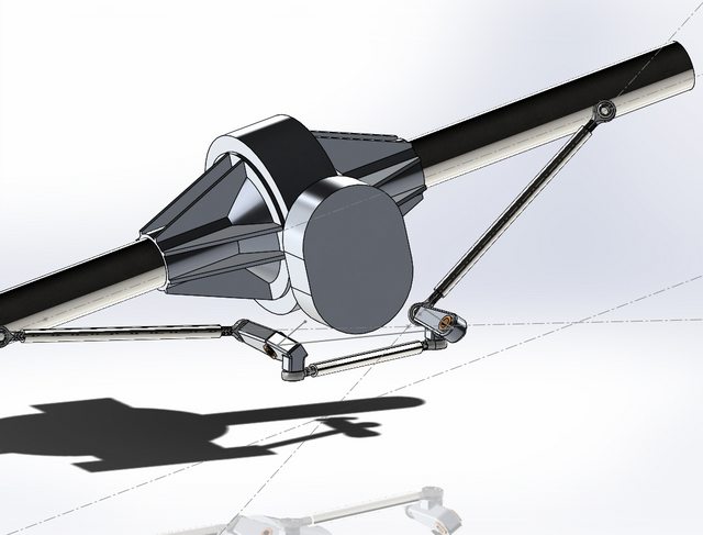
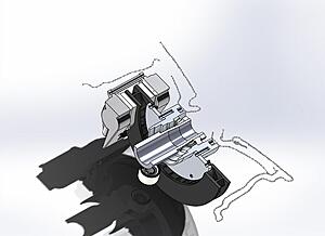
OK, so mocked up the Mumford into the chassis and ... long story short, it has to go through the quick change. No good. So I sat and had a think about linkages and came up with this.
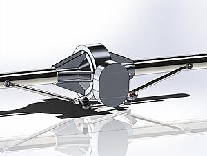

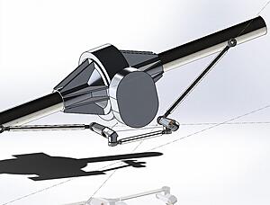
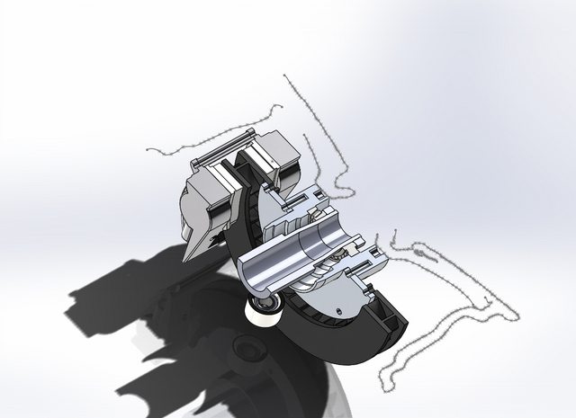
So the bellcranks are at an angle on pivots fixed to the frame, and the center link is angled front to rear - right side 2" forward of the pivot, left side 2" behind so as to link the angles of the bellcranks. Note how there's now a very nice space behind everything for accessing the quick change gears too. Pretty happy with how that worked out.

So the bellcranks are at an angle on pivots fixed to the frame, and the center link is angled front to rear - right side 2" forward of the pivot, left side 2" behind so as to link the angles of the bellcranks. Note how there's now a very nice space behind everything for accessing the quick change gears too. Pretty happy with how that worked out.
 11-12-20, 11:26 AM
#88
spoon!
Thread Starter
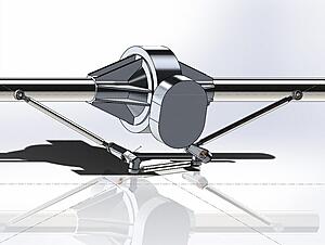
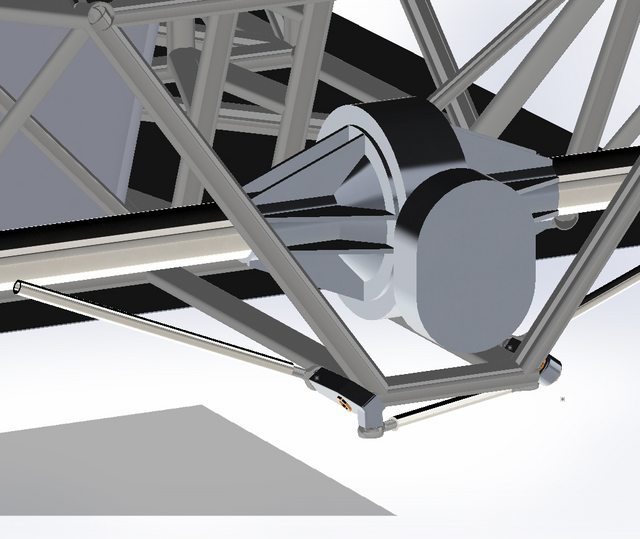
I'm essentially thinking that the tube corner will have some gussets and reinforcement that a ground stud bolts to so not a _lot_ more stuff to make it work than the mockup there.
If I were smart, the subframe carrying everything behind the chassis there would be small thinwall tube, and, say, held on to the rest of the chassis with a minimal number of bolts. Say, for example, 4 bolts and pull the cell and wing mount off.
If I were smart, the subframe carrying everything behind the chassis there would be small thinwall tube, and, say, held on to the rest of the chassis with a minimal number of bolts. Say, for example, 4 bolts and pull the cell and wing mount off.
11-12-20, 12:53 PM
#89
I worked on a Trans Am Corvette that was configured as you describe. As I recall the cell was contained in a cage that was held to the back of the car with 4 5/16" pins. Disconnect the fuel lines, pull the pins and roll all of that stuff out of the way on a floor jack. The cell cage also incorporated the rear crash bumper but it was throw away. Everything ahead of the cell was stout rectangular/square tube stuff.
The car was built for/by Larry Park out of CA. He was a big time corvette guy with a number of Solo Nationals titles. He also dabbled in GT1 and Trans Am.
https://www.racingsportscars.com/dri...-Park-USA.html When I worked on it was owned by a guy in KC that was prepping it for sale.
The car was built for/by Larry Park out of CA. He was a big time corvette guy with a number of Solo Nationals titles. He also dabbled in GT1 and Trans Am.
https://www.racingsportscars.com/dri...-Park-USA.html When I worked on it was owned by a guy in KC that was prepping it for sale.
11-12-20, 01:19 PM
#90
spoon!
Thread Starter
Yeah, I'm shamelessly stealing a lot of ideas from Trans Am stuff. If I were trying to make a living by making these there's no way I'd do a round tube chassis (or maybe a CNC notcher would make it easier?) but for a one-off for myself, what the heck.
12-08-20, 12:09 PM
#91
spoon!
Thread Starter
Various supporting stuff going on; also holidays and jobhunting and stuff. Whatever.
Decided to start playing with the AEM dash designer software.
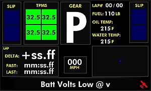
Standard "race" page - obviously no tach, that's handled by shift lights. Intent is that really, anything on the LCD either lights up a color that can be seen in peripheral vision, or isn't that important. I personally like numbers for a "I'm glancing at this every so often or under pace car conditions"; input appreciated. Most of the layout concepts are cribbed from various IMSA GTLM class cars; probably closest to the Corvette.
Oh yeah, the TPMS box with temperatures is an "I'd like this eventually"; the sensors aren't hugely expensive but aren't necessary to get on track.

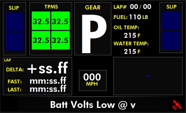
Alarm page for fun - this would be switched to at "shut the car down" levels of badness, though the text at the bottom is just the generic example warning for setup.
Decided to start playing with the AEM dash designer software.
Standard "race" page - obviously no tach, that's handled by shift lights. Intent is that really, anything on the LCD either lights up a color that can be seen in peripheral vision, or isn't that important. I personally like numbers for a "I'm glancing at this every so often or under pace car conditions"; input appreciated. Most of the layout concepts are cribbed from various IMSA GTLM class cars; probably closest to the Corvette.
Oh yeah, the TPMS box with temperatures is an "I'd like this eventually"; the sensors aren't hugely expensive but aren't necessary to get on track.

Alarm page for fun - this would be switched to at "shut the car down" levels of badness, though the text at the bottom is just the generic example warning for setup.
 02-12-21, 11:05 AM
#93
spoon!
Thread Starter
Well in advance of needing it but I wanted something that spat out CAN streams for testing and it's just too cool... ordered https://trailbrake.com/tire-tpms/ the other day. Not as high of frequency read out as some of the motorsport ones, but something like 15x less expensive than the next least expensive easily-loggable one I was able to find...
02-27-21, 06:45 PM
#94
spoon!
Thread Starter
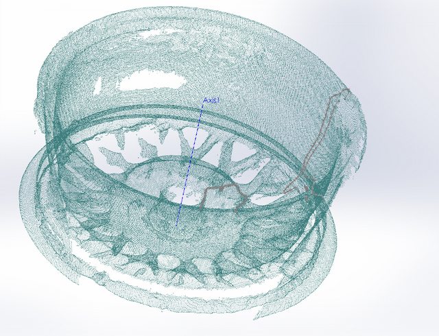
Proof of concept... so had an FC BBS wheel kicking around, so been working on a work flow to get 3d scans into solidworks. And, well, here we are! No I was not very careful about the spokes.
I'm not going to mess with it too far but if you look at the profile stuff, I got it to spit out something I can convert to a 3d sketch and blah blah blah, dimensionally accurate wheel inside barrel to design brake fitment around. I have an actual light 15x7 wheel inbound next week to design stuff around to be sure.
03-06-21, 08:13 PM
#95
spoon!
Thread Starter
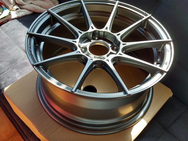
Well look at this shiny fellow that showed up! Obviously will go and scan. Maybe not the style I'd go for all else being equal, but in the world I live in... $135 shipped, and 10lbs? Heck yeah.
The following users liked this post:
gracer7-rx7 (11-21-21)
03-06-21, 11:18 PM
#96
spoon!
Thread Starter
If I were being careful, I'd incorporate a few different scans to make sure I got al the features so I could reverse engineer properly. Instead I got impatient.
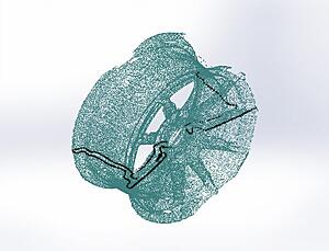
Again sort of a rough scan but I got the inside and outside surfaces
And there's the moneyshot!

Again sort of a rough scan but I got the inside and outside surfaces
And there's the moneyshot!
04-09-21, 11:01 AM
#97
spoon!
Thread Starter
Forgot to update another thing... so I'm ready to get the CNC tube notcher steel and bang that together but... the truck seems to have suffered the fate of all midwestern vehicles and acquired frame holes. That's almost done. In the mean time working on other stuff.

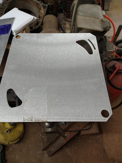
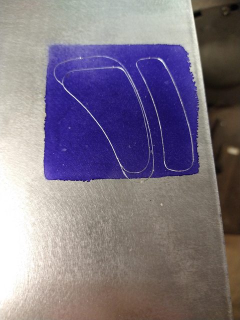
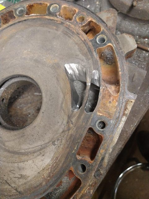
Mazdatrix Turbo 2 half bridge pattern template
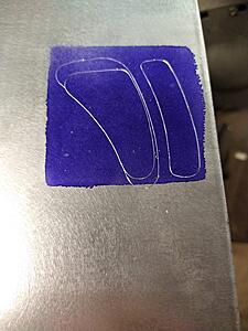
Scribed onto the RB j-bridge template; notice the later closing.
I figure the half bridge template is a bit more radical on the closing since it's the EFI irons where the primary (center) ports are smaller... so I'm pretty sure 12A irons can go that big if you're careful, ergo, **** it, moar brap.

Junk iron obviously but looks like I don't run out of iron.
Sitting and chewing it over, I have a hypothesis that a CNC'd female mold would be easier to work with than "make plug, pull female molds" especially since I can engineer in parting features in the mold. There's a few different ways to do it, so I need a test piece to figure out what works.
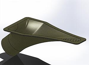
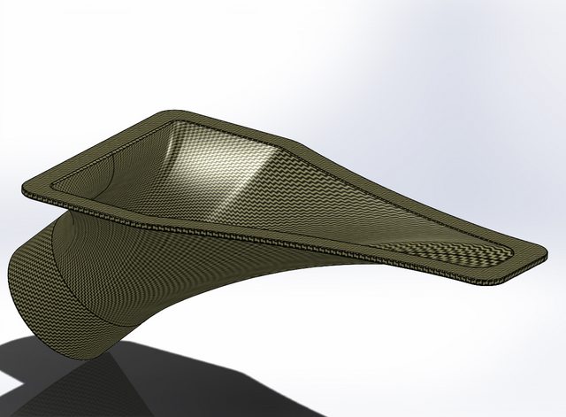
Enter test piece. Not that I need NACA ducts desperately or anything but it's cool shaped, kinda complicated but not too bad, needs a 2 part mold, and not too big.
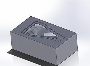
Female cavity generated in CAD
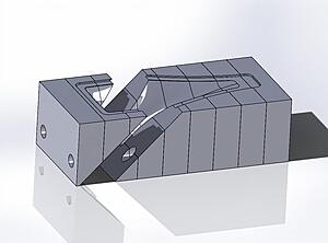
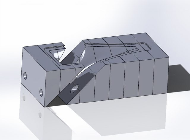
Sliced into 2 inch sections, with alignment features for rods and separated where it'll have to in order for the mold to come apart.
First hypothesis on construction is "CNC rout out of pink styrofoam"; so cut slices on the CNC router, glue together, and gelcoat the tooling surfaces. Maybe lay up glass reinforcement too; the whole point of this is figuring out what's necessary. Also to see if the whole mess will stand up to 250F where the prepreg cures at. I think though that styrofoam might be kind of risky so redid the slicing for 3/4" MDF which will be much more solid molds. Anyway, the whole point is something for vacuum bagged 250F cure prepreg.
Mazdatrix Turbo 2 half bridge pattern template
Scribed onto the RB j-bridge template; notice the later closing.
I figure the half bridge template is a bit more radical on the closing since it's the EFI irons where the primary (center) ports are smaller... so I'm pretty sure 12A irons can go that big if you're careful, ergo, **** it, moar brap.
Junk iron obviously but looks like I don't run out of iron.
Sitting and chewing it over, I have a hypothesis that a CNC'd female mold would be easier to work with than "make plug, pull female molds" especially since I can engineer in parting features in the mold. There's a few different ways to do it, so I need a test piece to figure out what works.
Enter test piece. Not that I need NACA ducts desperately or anything but it's cool shaped, kinda complicated but not too bad, needs a 2 part mold, and not too big.
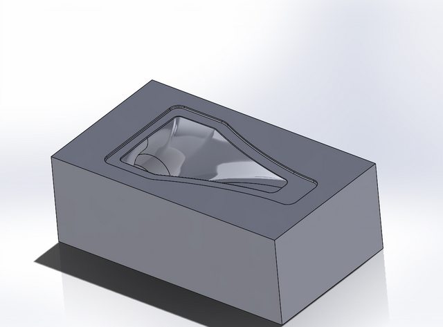
Female cavity generated in CAD
Sliced into 2 inch sections, with alignment features for rods and separated where it'll have to in order for the mold to come apart.
First hypothesis on construction is "CNC rout out of pink styrofoam"; so cut slices on the CNC router, glue together, and gelcoat the tooling surfaces. Maybe lay up glass reinforcement too; the whole point of this is figuring out what's necessary. Also to see if the whole mess will stand up to 250F where the prepreg cures at. I think though that styrofoam might be kind of risky so redid the slicing for 3/4" MDF which will be much more solid molds. Anyway, the whole point is something for vacuum bagged 250F cure prepreg.
 04-22-21, 05:46 PM
#99
spoon!
Thread Starter
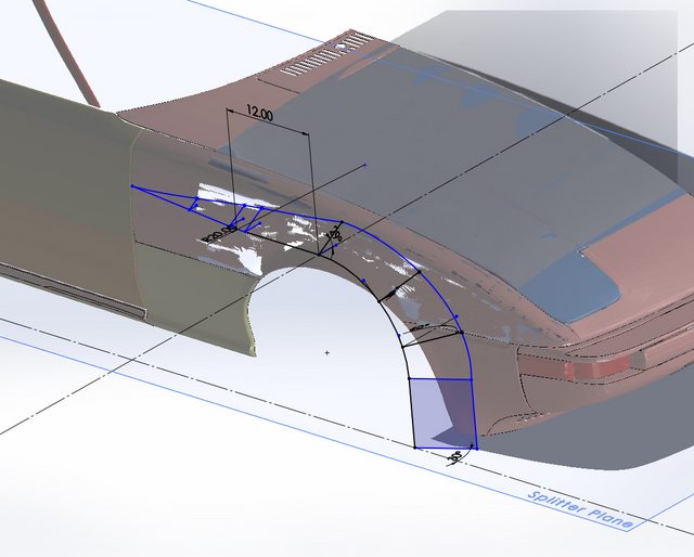
Laying out more bodywork; did the doors because they're relatively easy plus provide perspective for some other stuff
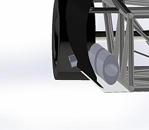
Borla makes some rotary-specific mufflers - hey look, two of them fit! I may just fab my own to make sure it damn well lasts but now have a good idea how much space to play with.
Mufflers will probably be inside a box lined with heat shielding, fed with air from the wheel well at the front; should help control cockpit temperatures.
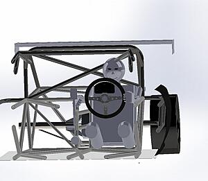
A bit of perspective on how far inboard the driver is pushed - door skin is at stock width, driver model is roughly scaled to, well, me.
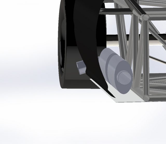
Borla makes some rotary-specific mufflers - hey look, two of them fit! I may just fab my own to make sure it damn well lasts but now have a good idea how much space to play with.
Mufflers will probably be inside a box lined with heat shielding, fed with air from the wheel well at the front; should help control cockpit temperatures.
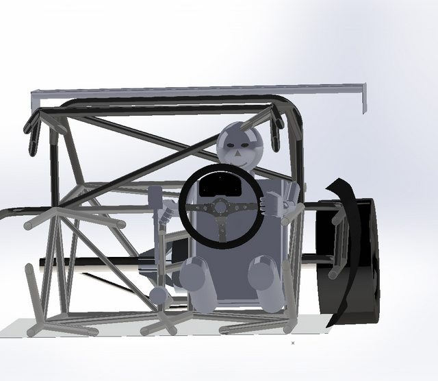
A bit of perspective on how far inboard the driver is pushed - door skin is at stock width, driver model is roughly scaled to, well, me.
The following users liked this post:
mustanghammer (04-22-21)
04-28-21, 01:18 PM
#100
spoon!
Thread Starter

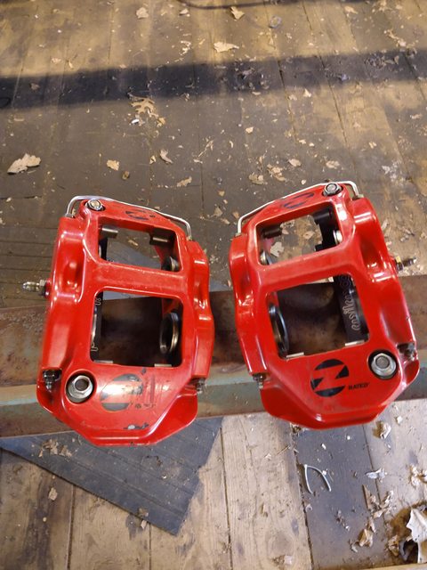
Well hello... sometimes the price is right. Pair of Performance Friction ZR34 front calipers. Monoblock radial mount intended for circle track but they get used everywhere because they great value. Especially with what I paid.