Huyler's Street & HPDE Build


I'm between the RA1 or a set of the BFG Radial T/A which will probably make a better street tire for daily driving. The Vredestein Sprint Classic is also an option on TireRack, but I think the white letters of the BFG is a better look for the car.
I'm not after any epic laps when the track is wet. Without ABS and traction control I can't keep up anyway. My original wheels have some Chinese brand tires on them now which have absolutely no grip and I didn't even feel safe driving on the street with them. I didn't dare bring them to the track as they were around 10 years old. So that's why I just stuck with the Nittos when it was wet. They were OK at first, but as I wore them down they stopped channeling water and just floated over the track.
I'm not after any epic laps when the track is wet. Without ABS and traction control I can't keep up anyway. My original wheels have some Chinese brand tires on them now which have absolutely no grip and I didn't even feel safe driving on the street with them. I didn't dare bring them to the track as they were around 10 years old. So that's why I just stuck with the Nittos when it was wet. They were OK at first, but as I wore them down they stopped channeling water and just floated over the track.
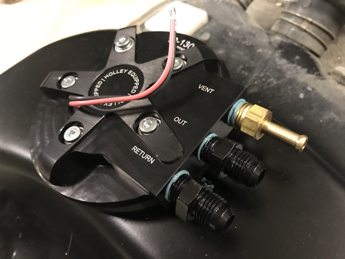

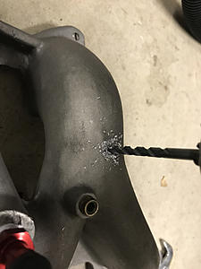
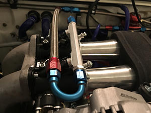
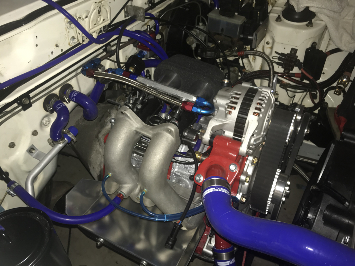
Finishing touches on the intake manifold.
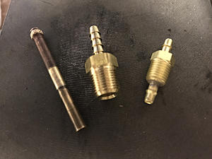
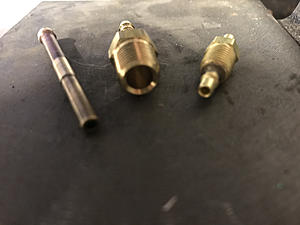
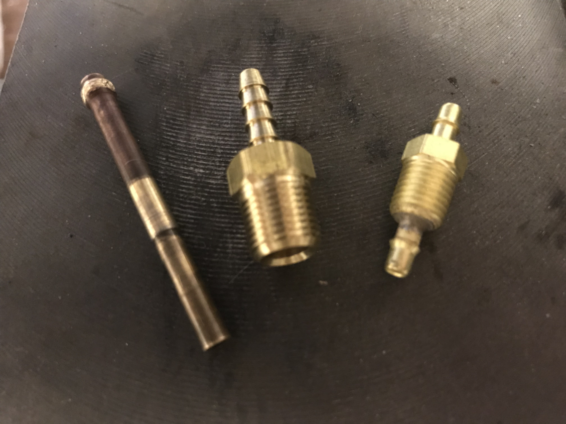
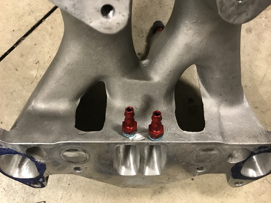
First, I sourced some fittings that are 1/8" NPT that have 1/8" barbs on both sides. On the left is the Nikki injector removed for reference. In the center is the fitting I have seen others use, but they complained of smoke on startup and when they hit the throttle. I hope to resolve this with the fitting on the right which has constant inside diameter and will protrude into the center of the intake to help with atomization of the oil. It's about as good as I can get without using the later gen injectors.
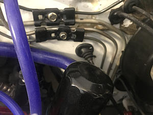
Near the primaries, someone had already drilled holes and there were some brake bleeder screws in there. I removed those and tapped for 1/4" fittings and installed some 1/4" barbs.
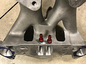
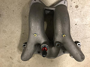
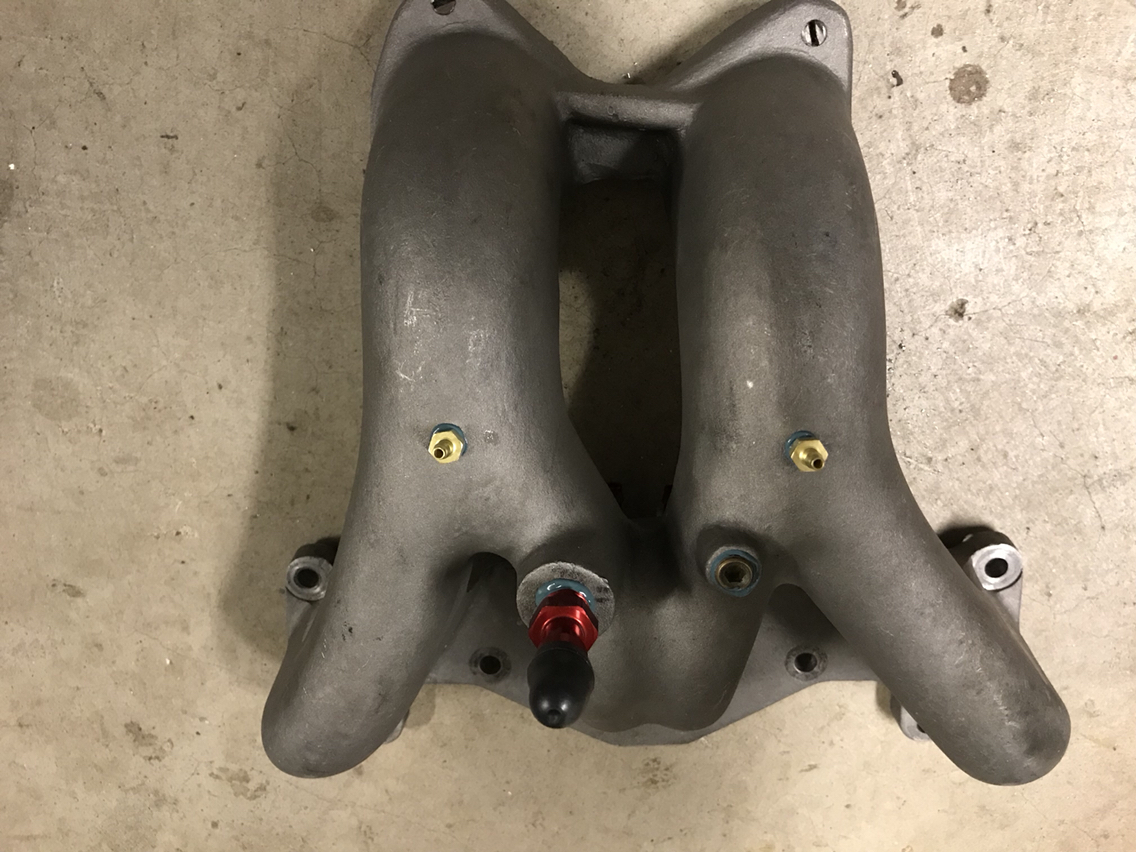
I put my new oil injection fittings higher up before the split so that oil would pass into both sides of the intake.
No turning back now...
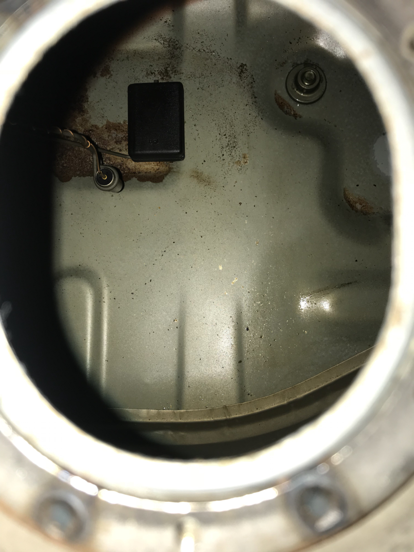
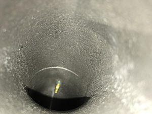
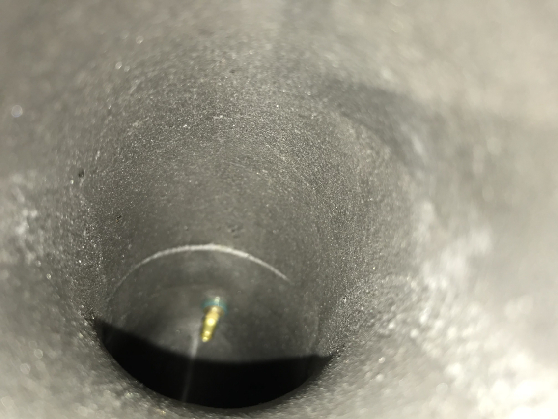
A quick shot of what they look like from the inside.
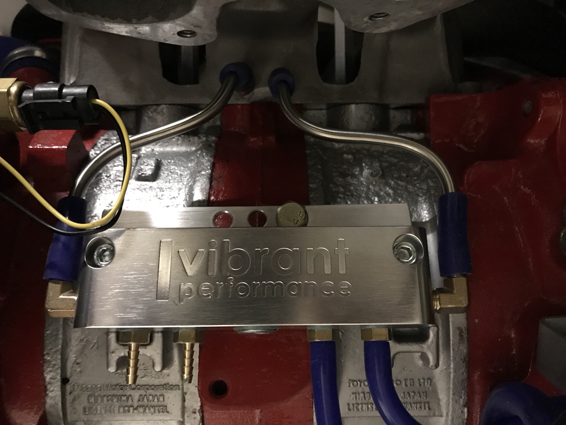
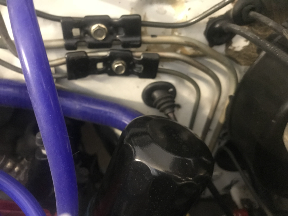
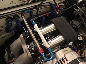
Lastly, I bent some 1/4" tubing to connect to my vacuum manifold. I was just going to use hose, but the throttle linkage is very close and I needed some tight precise bends to clear it. It's a pity this will all be hidden when it's done. I'll add some clamps during final assembly.

First, I sourced some fittings that are 1/8" NPT that have 1/8" barbs on both sides. On the left is the Nikki injector removed for reference. In the center is the fitting I have seen others use, but they complained of smoke on startup and when they hit the throttle. I hope to resolve this with the fitting on the right which has constant inside diameter and will protrude into the center of the intake to help with atomization of the oil. It's about as good as I can get without using the later gen injectors.

Near the primaries, someone had already drilled holes and there were some brake bleeder screws in there. I removed those and tapped for 1/4" fittings and installed some 1/4" barbs.
I put my new oil injection fittings higher up before the split so that oil would pass into both sides of the intake.
No turning back now...

A quick shot of what they look like from the inside.
Lastly, I bent some 1/4" tubing to connect to my vacuum manifold. I was just going to use hose, but the throttle linkage is very close and I needed some tight precise bends to clear it. It's a pity this will all be hidden when it's done. I'll add some clamps during final assembly.
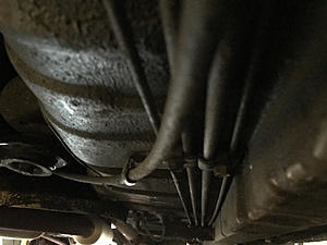
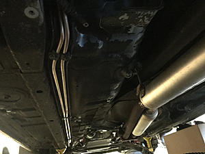
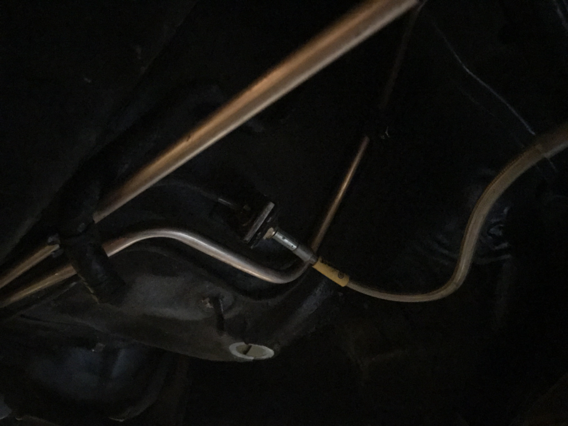
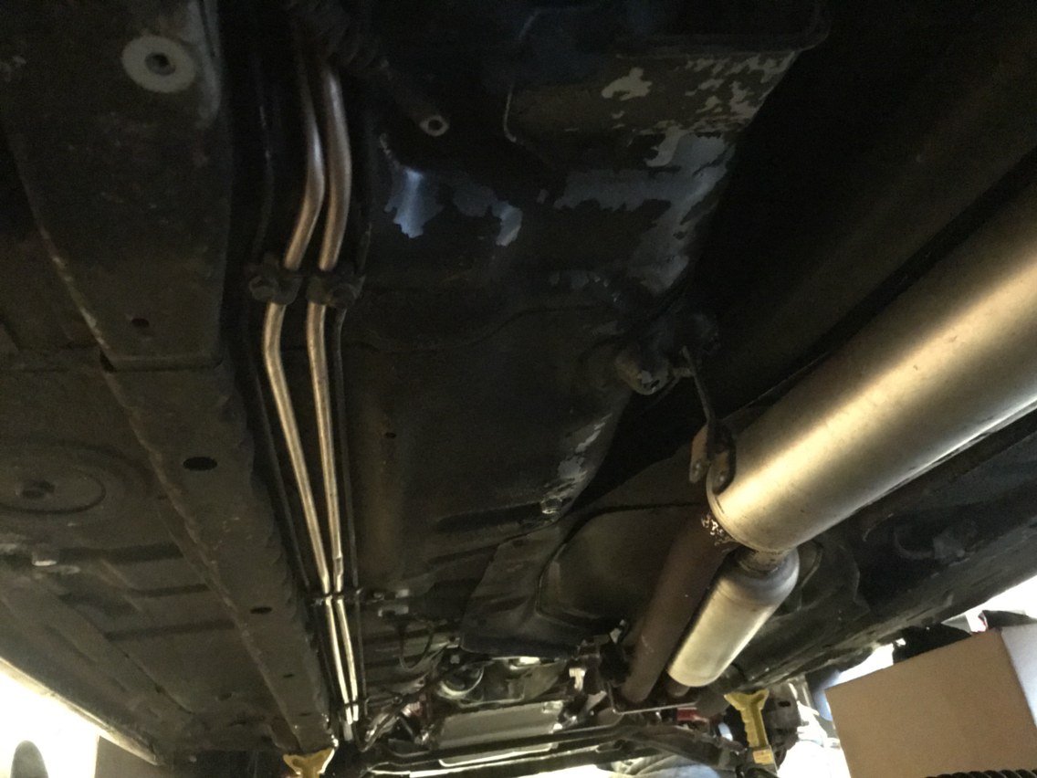
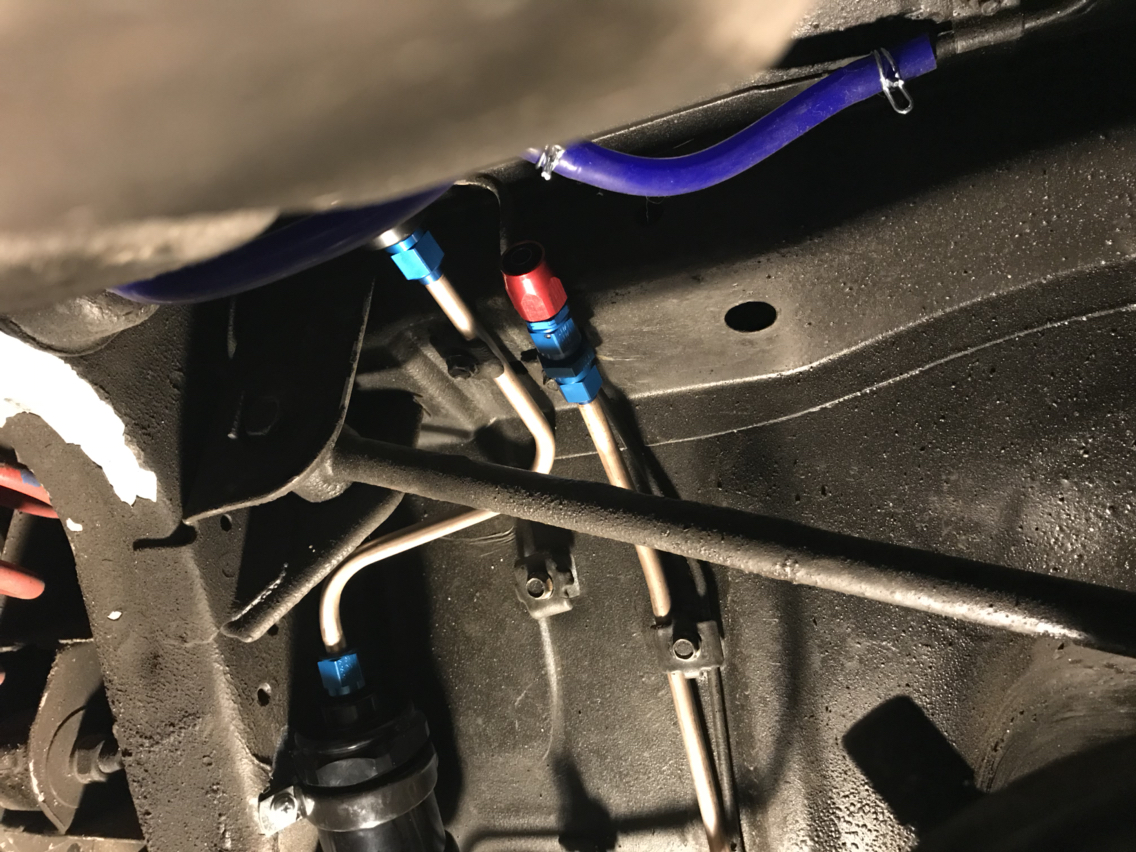
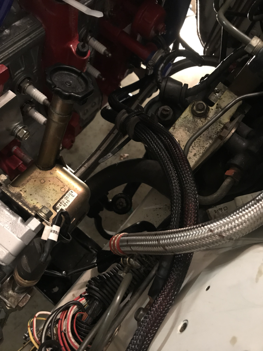
Back under the car during my lunch break today (I work from home) and I started on the new fuel lines. Upgrading to 3/8" nickel-copper with flares AN fittings.
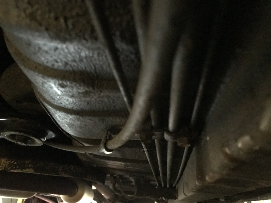
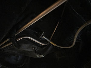
Some before shots...
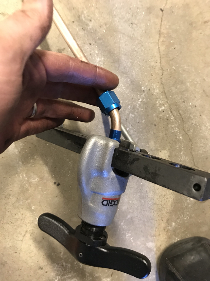
Getting started...
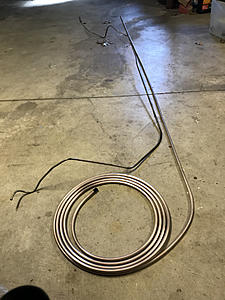
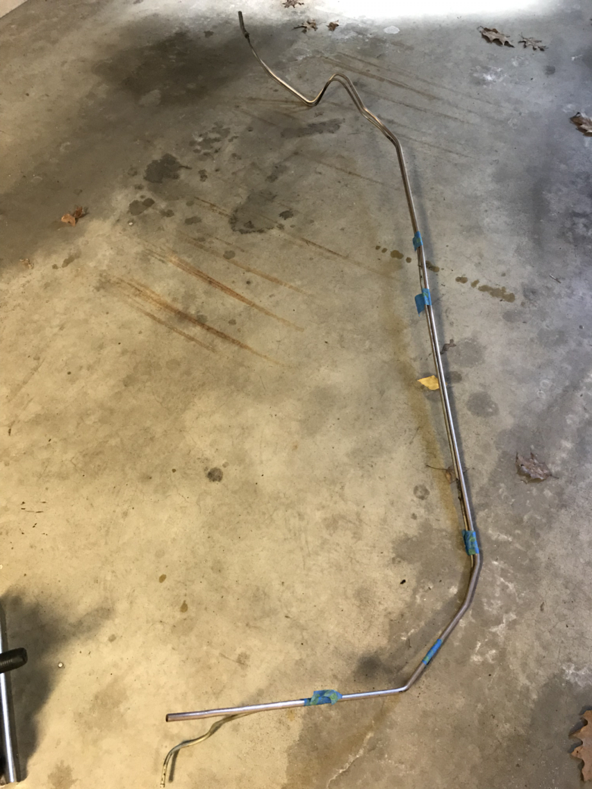
Bending in progress. This was a little more tedious than I had anticipated.

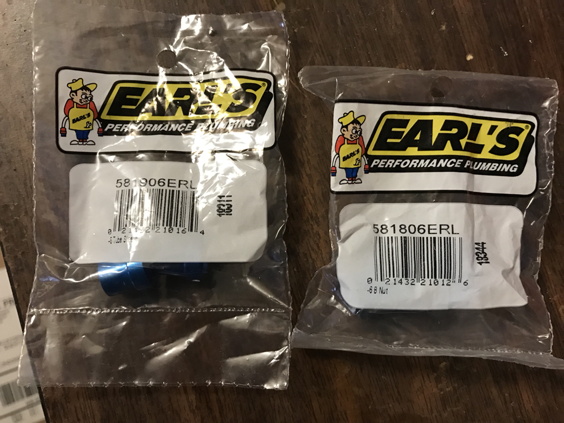
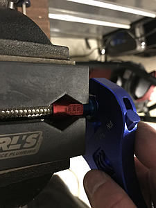
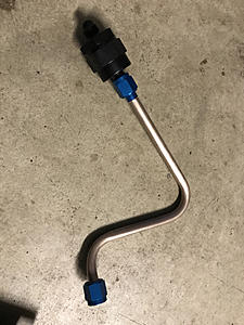
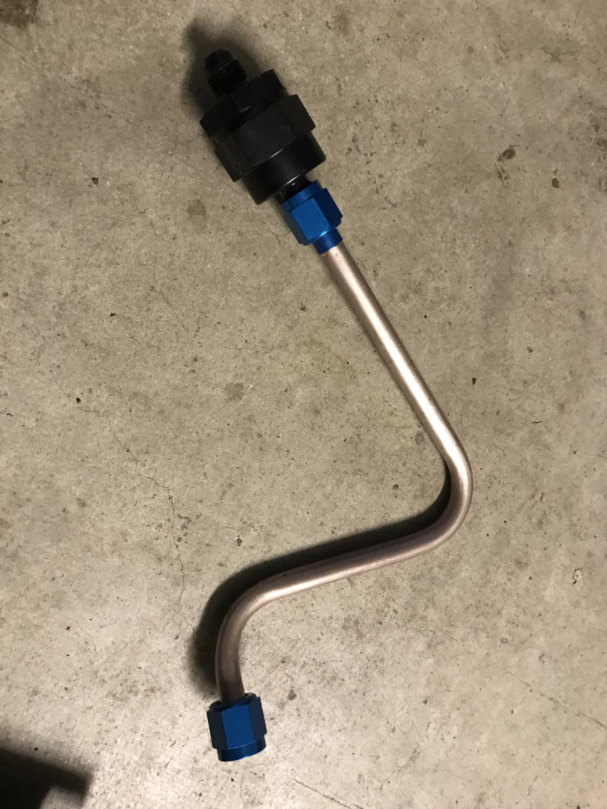
And the fittings...
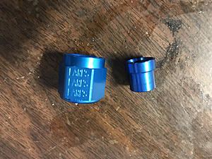
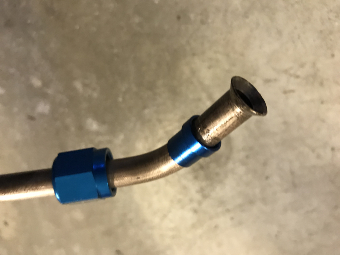
Always remember to put the fitting on first!!!
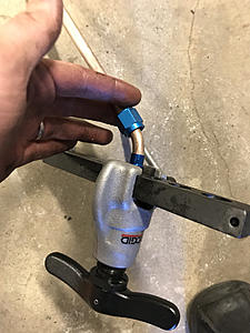
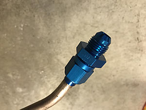
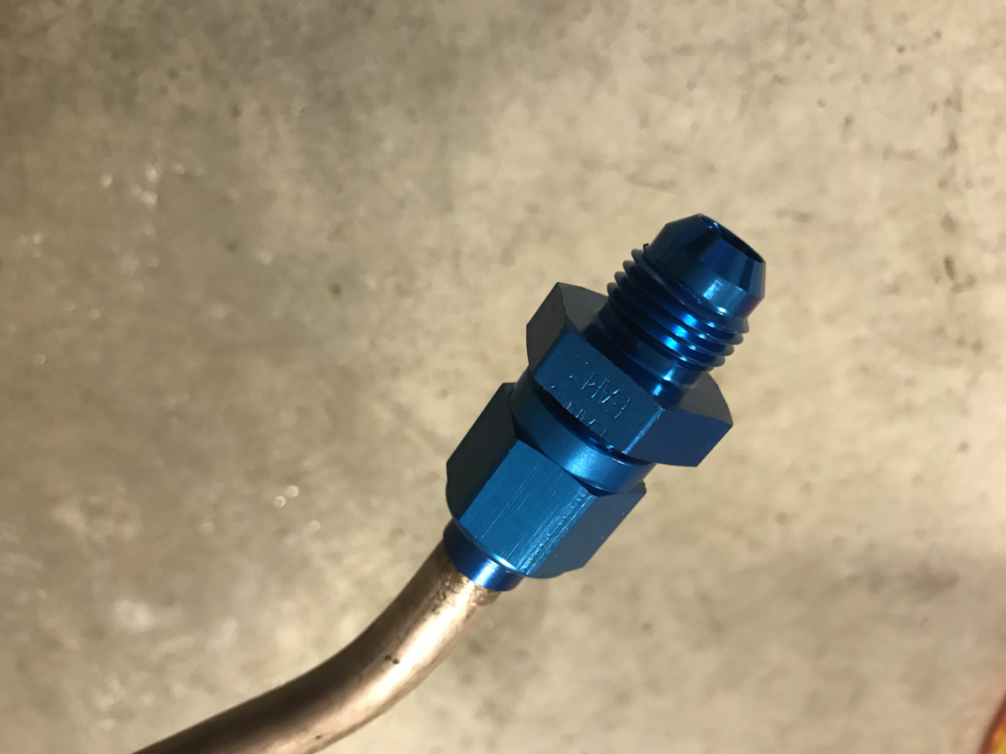
That was easy

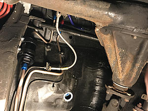
Ready for a soft line to the tank
That's as far as I got today. I'm hoping to finish up this weekend.
Some before shots...

Getting started...
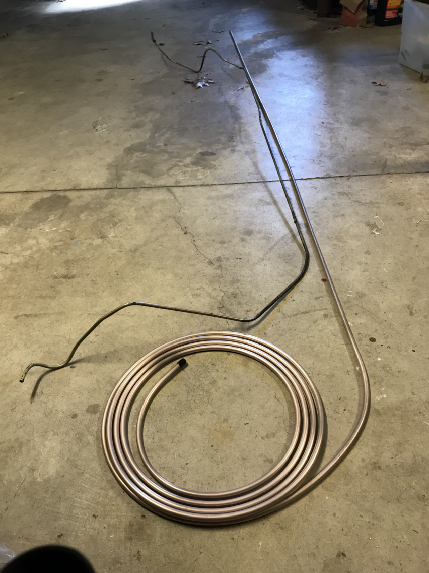
Bending in progress. This was a little more tedious than I had anticipated.
And the fittings...

Always remember to put the fitting on first!!!
That was easy
Ready for a soft line to the tank
That's as far as I got today. I'm hoping to finish up this weekend.

ancient wizard...
Joined: Sep 2014
Posts: 2,335
Likes: 262
From: Maryland
The fittings...once you�ve done fuel/brake line fabrication for a while...you�all still do it.
Best time for this to happen is on a section with a lot of intricate bends that has the perfect length...
Best time for this to happen is on a section with a lot of intricate bends that has the perfect length...

Ahhhh... I remember doing that. Bending by hand using the old line as a reference was a great way to get the new line bent correctly, and I also forgot once or maybe twice to put the new fitting on before flaring the end... One of the more frustrating parts of my build for sure!
Loving the build - it's looking great.
Loving the build - it's looking great.
Frustrating is an understatement. I don't have a lift so the car is on jack stands. It's hard to mark bends, remove the line, make the bend, then get it back up into place without it snagging on other stuff in the engine bay and under the car. Anyway, I'm finally finished with the return line, so now I just have to repeat it all for the feed line.
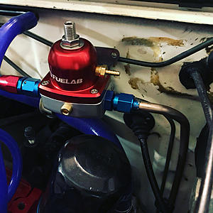

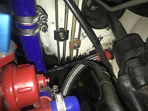
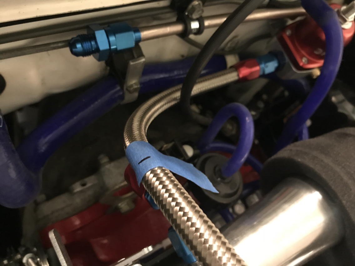
Been working all afternoon. I still have to mount the fuel filter but I am so close! The feed line is done from the engine bay to fuel filter and I took a break from that to put together the soft lines in the engine bay so I could see how it's all going to look...


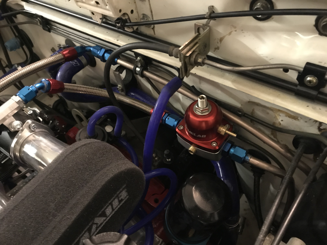
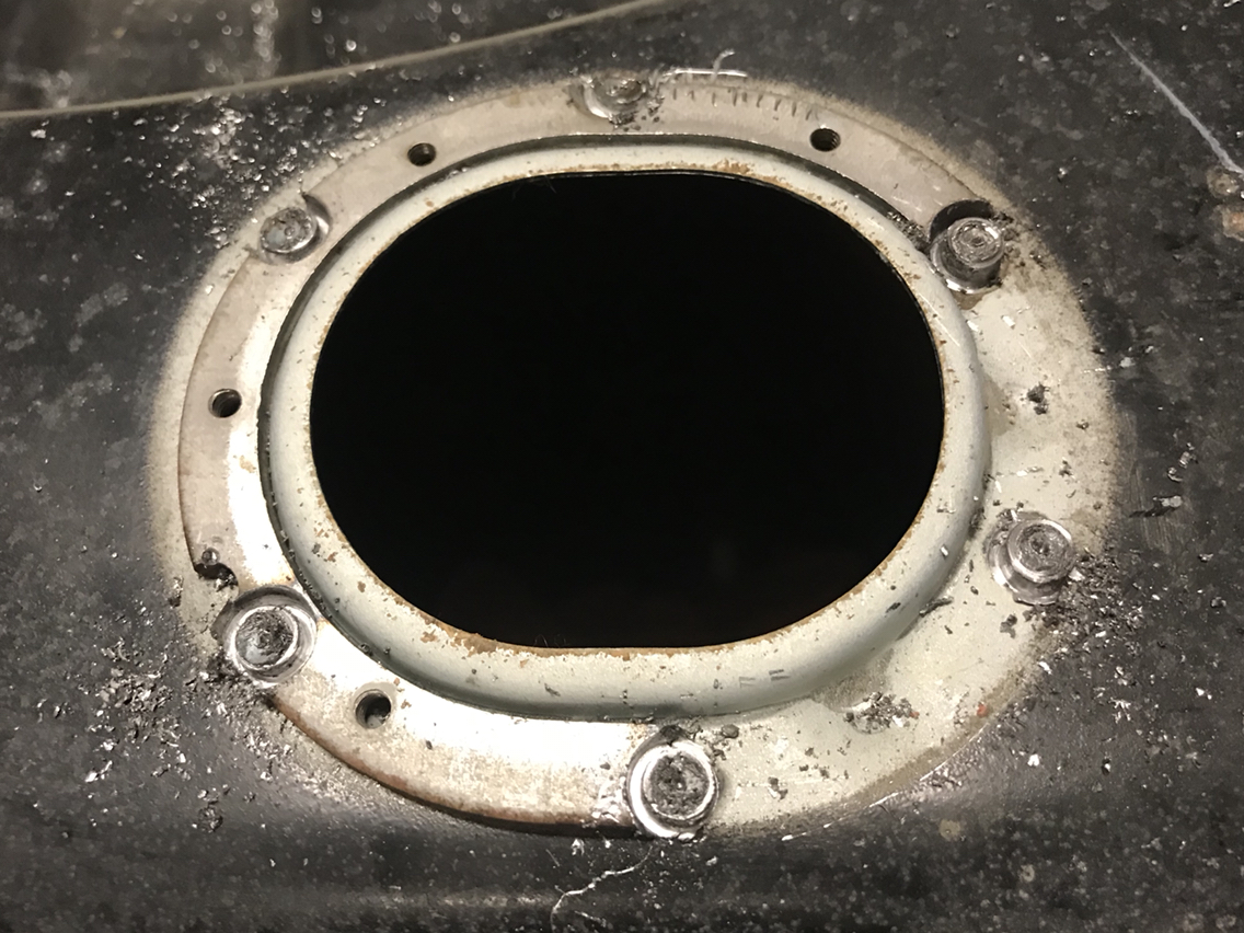
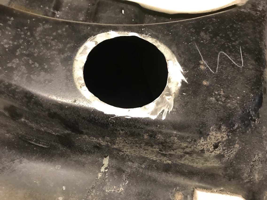
The last of the hard line work is complete. No holes were drilled. I used the two mounting holes for the OEM check valve to mount the Fuelab 10 micron filter. I bought this check valve from vibrant a while back. I'm hoping it will help keep pressure in the lines for easy startup.


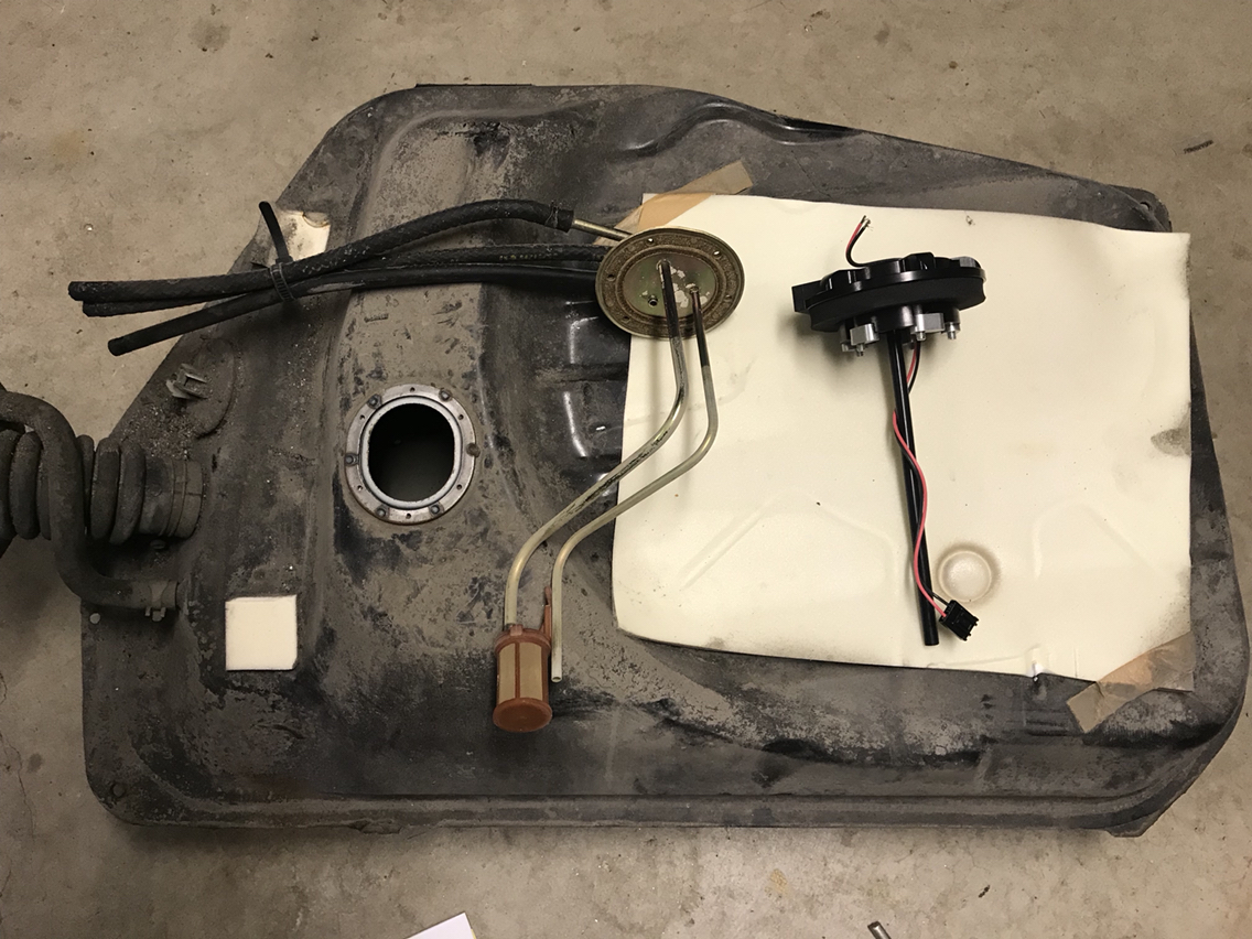
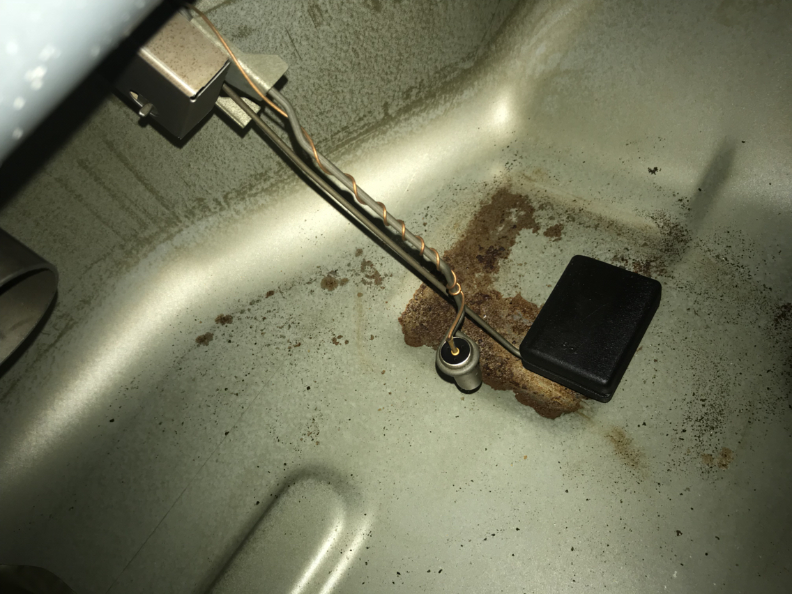
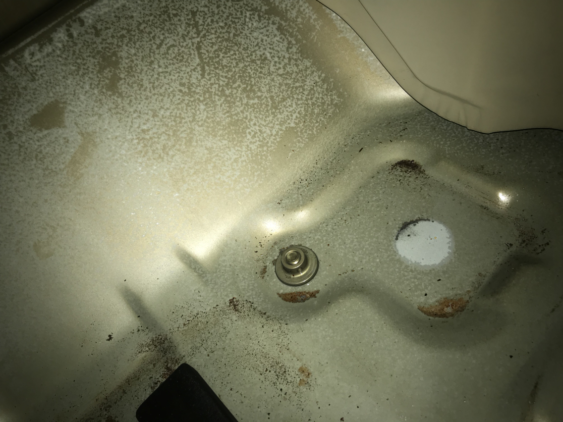
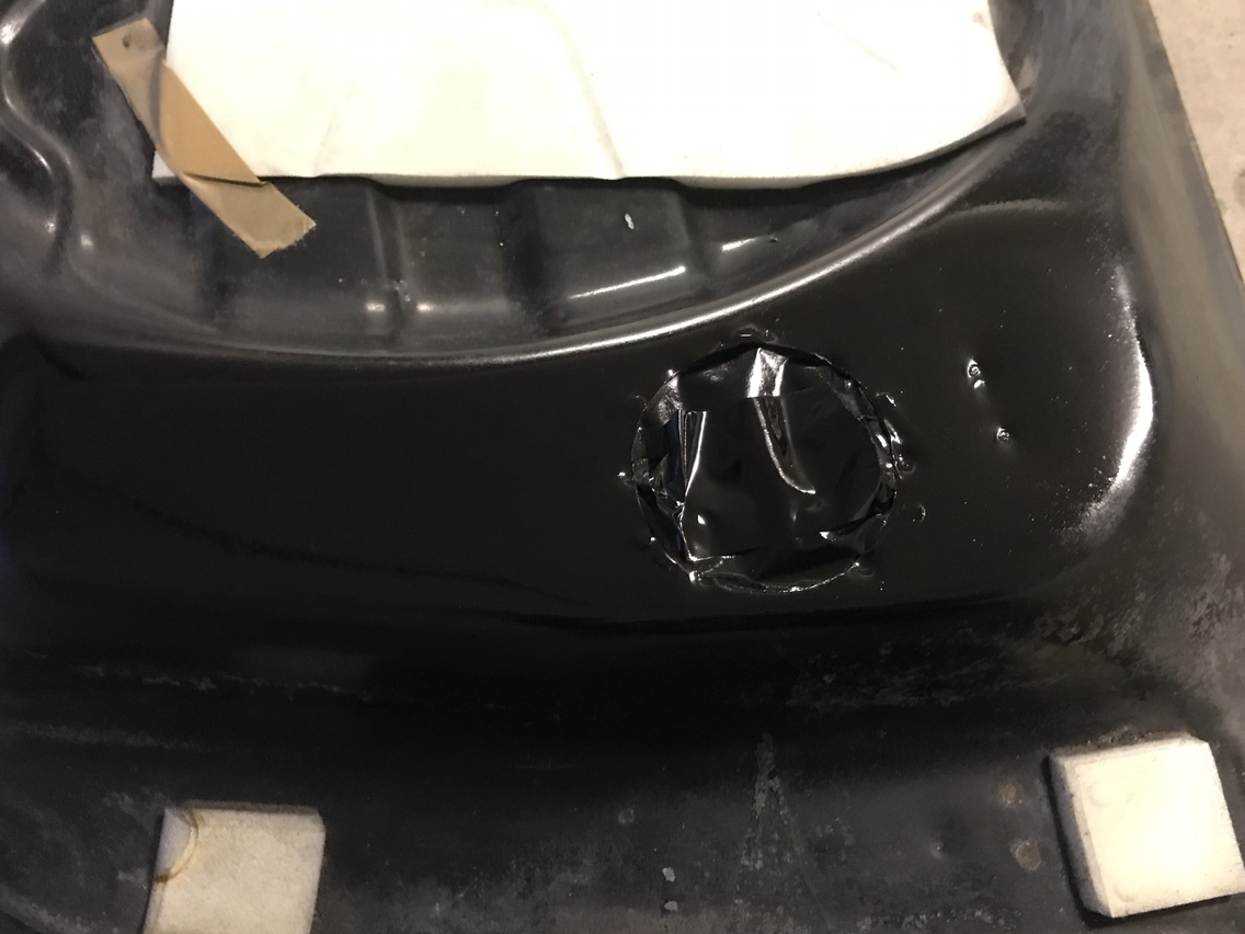
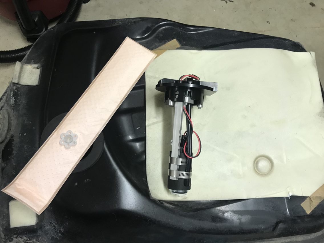
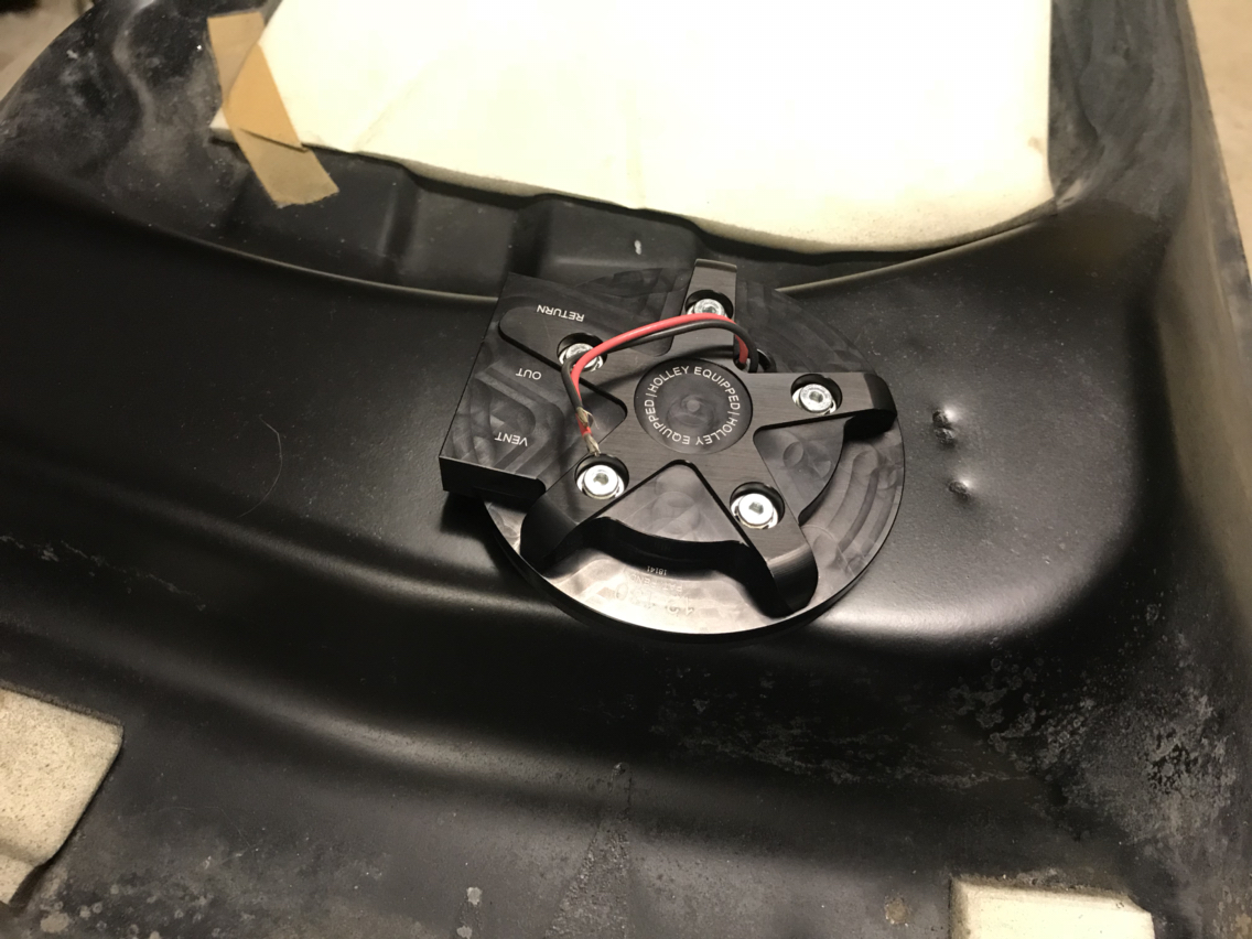
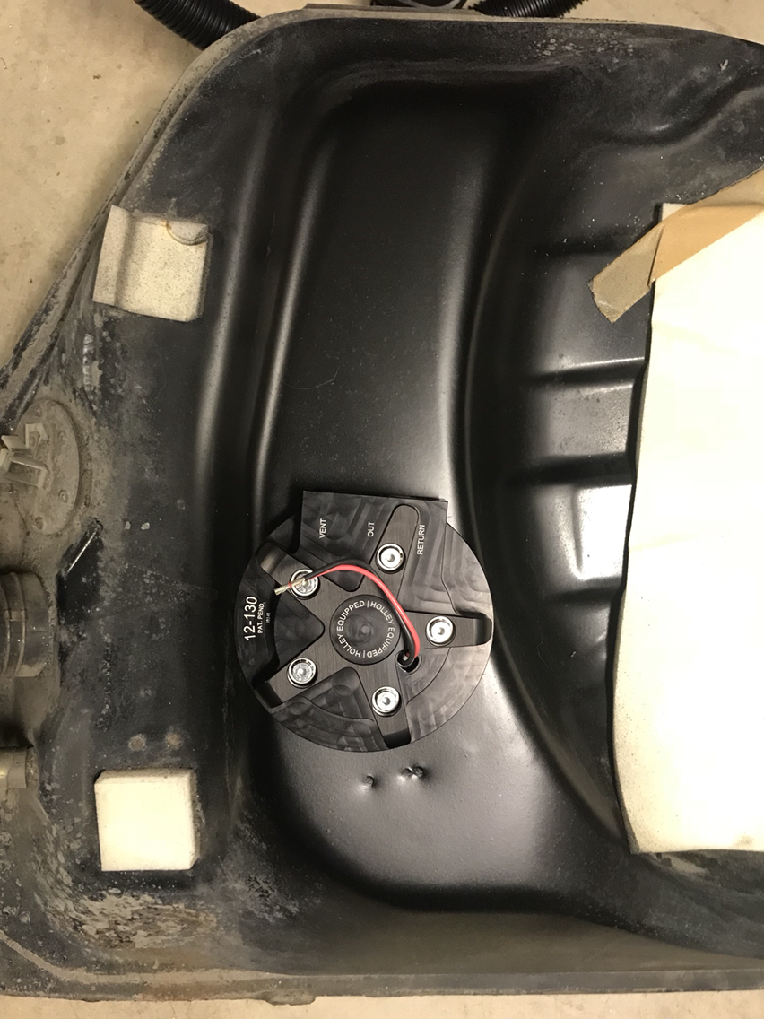
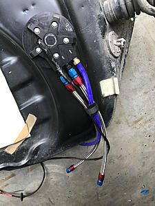
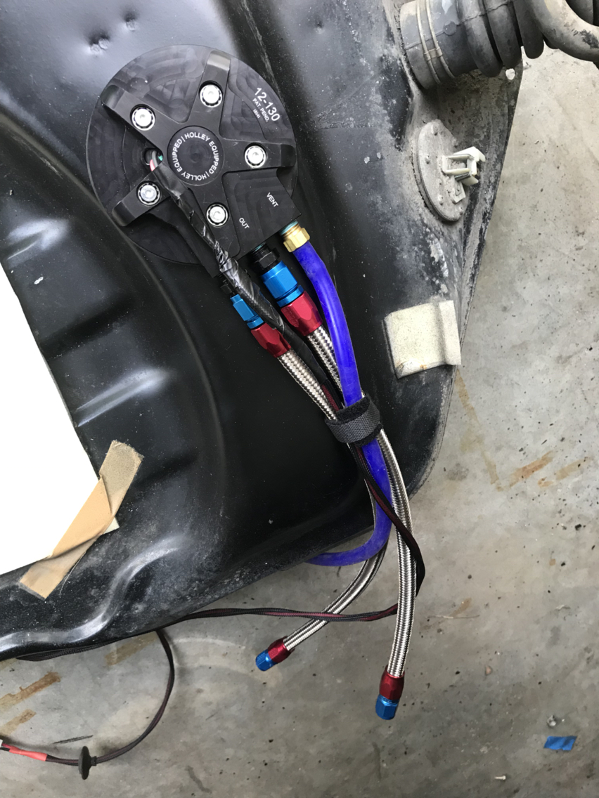
Well, the fuel tank is finally back in. Came out nicely. Power to the fuel pump is 12 gauge wire tucked inside some flex loom and secured to the underside using some of the extra fuel line clips.
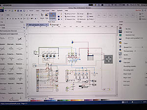
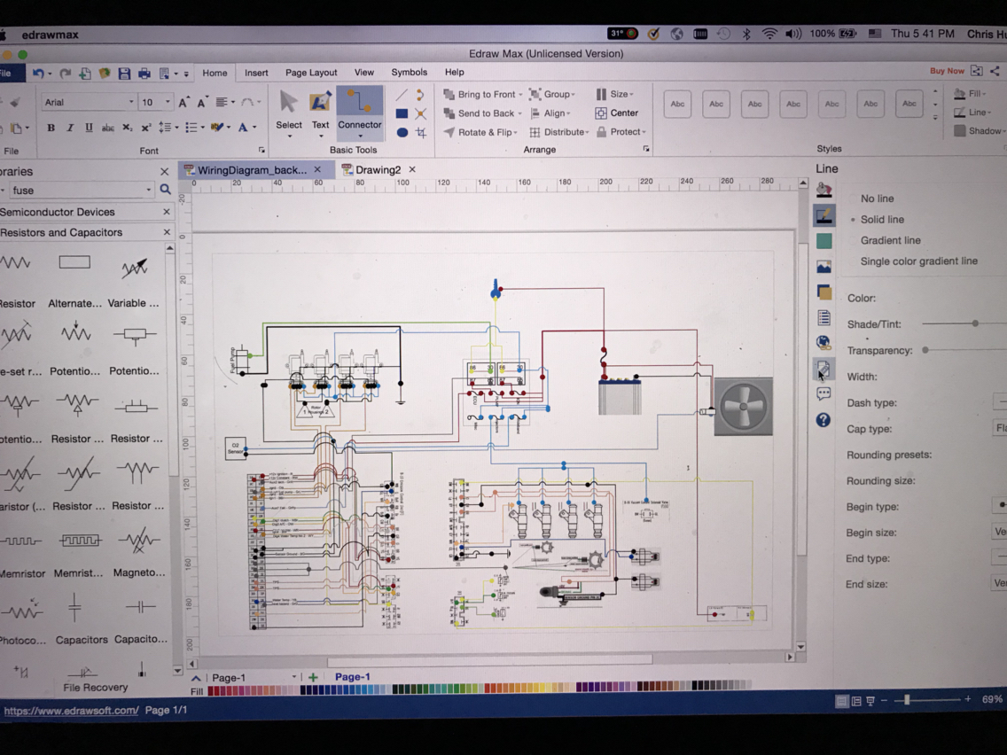
I had my wisdom teeth removed on Friday, and was supposed to take it easy over the weekend. So I spent my time figuring out the wiring harness. Some of you helped me sort this out in my other thread. I have a res version of this for anyone interested but here's a quick export that shows my plans.
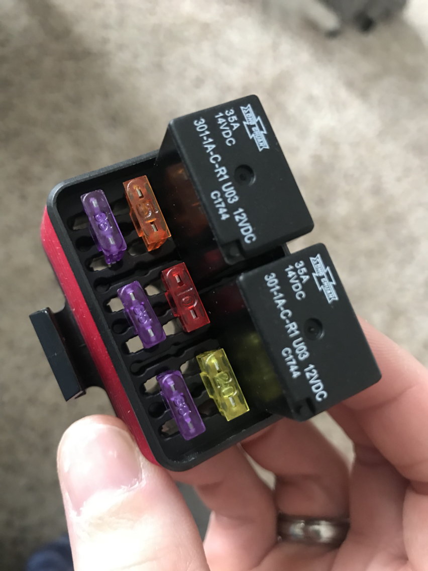
Long story short, a new 6 fuse 2 relay box to cover coils, fuel pump, and EFI related components. IGN-1A coils will be tucked up by the brake booster. A loom will run to the passenger floor for the Adaptronic 440d ECU. I will be using the OEM loom to the engine bay reusing all the emissions computer connections for other things.

I had my wisdom teeth removed on Friday, and was supposed to take it easy over the weekend. So I spent my time figuring out the wiring harness. Some of you helped me sort this out in my other thread. I have a res version of this for anyone interested but here's a quick export that shows my plans.
Long story short, a new 6 fuse 2 relay box to cover coils, fuel pump, and EFI related components. IGN-1A coils will be tucked up by the brake booster. A loom will run to the passenger floor for the Adaptronic 440d ECU. I will be using the OEM loom to the engine bay reusing all the emissions computer connections for other things.
www.AusRotary.com


Joined: Apr 2003
Posts: 905
Likes: 273
From: Melbourne, Australia
Nice wiring diagram! I need to do some planning for my rewire soon and was about to look into some freeware software that might help - I can see you've used eDraw Max - i might give that a go!
I just downloaded this software, not sure if there is a trial period or it just leaves watermarks when you export it. I think the license is like $160 so if I get locked out I'll just pay for it. It's a really good app. I tried a few others that were duds. It didn't have any built in widgets for connectors but I just inserted images I snagged from the workshop manual and then added hotspots to attach wires. You can drag things around the page with varying success but it will mess up your wire paths if you are **** retentive like me and want things evenly spaced.

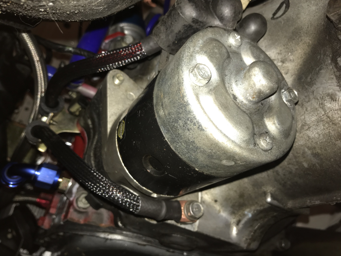
I think I just completed my last "under the car" task. New cables for the starter. 2ga wire that is a tad thicker than the original wires. Nice clean terminals, heat shrink, and some techflex loom. Probably didn't need the loom but it was the standard non-insulated stuff left over from a previous build. I have the nicer insulated loom that I will be using for the more sensitive engine harness wires.

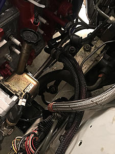
I'm also trying to figure out where I want the new fuse box. I think it will look nice right here piggy backed over the fusible links.

I know "wire tucks" are all the rage, and I will keep my engine harness clean and tidy, but I just don't feel like cutting up the factory harness to hide things I may need access to. So as you read on, don't expect to see my hack up wire looms in an effort to hide a 12" run of wire between the fuse box and the firewall. The only thing I see that accomplishing is a few extra instagram likes and years of unreliability as wires fail from being shifted around.
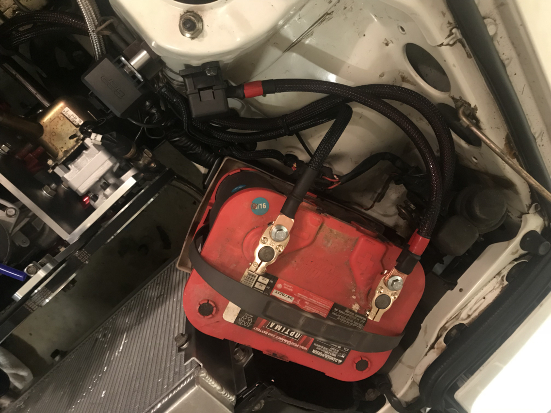
Last bit of under car work for the foreseeable future. New cables for the starter. Brass terminals, heat shrink, and some left over techflex. I snagged the cable bracket off the old motor. Sorry to disappoint anyone that was expecting a wire tuck job or battery relocation. I will have clean wire tidy runs, but I'm not going through the effort to hide everything. I milled over the battery relocation for a while, but decided I want my storage bins, if I don't want my storage bins I want subwoofers or amps or something. Maybe that decision will change if/when i decide to add a turbo, but for now it's staying where it is.


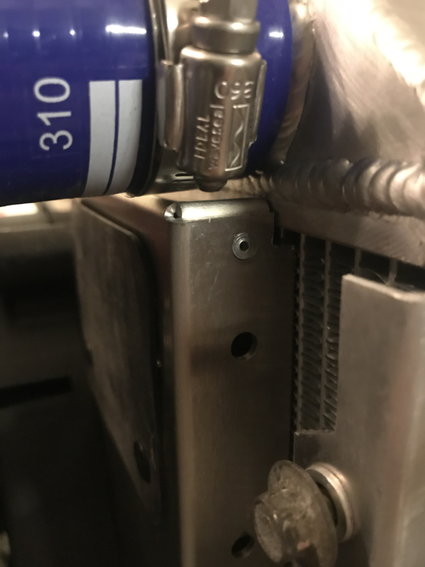
I also played around with where to put the new fuse box. This is the front runner, a small spacer and longer bolt to mount it in the same place as the fusible links.
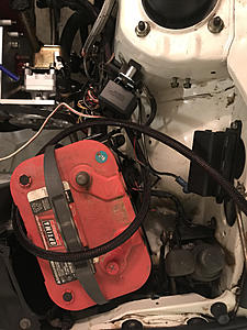


I also played around with where to put the new fuse box. This is the front runner, a small spacer and longer bolt to mount it in the same place as the fusible links.

Cleaning up the battery wiring.
I forget what I paid for these battery terminals but they aren't very good. I should have looked closer. Very small hex screw clamps them down...might not survive long term removal and installation. The top bolt was also hex and didn't have enough threads to hold two thick cable terminals, so I grabbed some 10mm bolts that were longer.
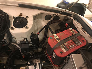

I forget what I paid for these battery terminals but they aren't very good. I should have looked closer. Very small hex screw clamps them down...might not survive long term removal and installation. The top bolt was also hex and didn't have enough threads to hold two thick cable terminals, so I grabbed some 10mm bolts that were longer.

Awesome work. Love how clean this build is.
What adapter did you end up going with the the water temp gauge on the back of your WP housing? I am installing a gauge there and was planning on driling and tapping a M16x1.5mm plug for 1/8NPT.
Did you do something similar for the oil pan plug?
https://www.rx7club.com/1st-generati...stall-1134222/
Also what electric fan did you go with? Looks like it fits really well.
Lots of questions haha.
Thanks!
For the water neck, I used this to replace the choke temp switch with a traditional GM sensor.
https://www.threadtoolsupply.com/alu...m16-38npt.html
For Oil temp, I just bought a Racing Beat oil filter pedestal adapter. It allows me to add oil pressure sensor too, but I don't have a sensor for that yet so I blocked off the extra port.
For air temp, I don't have a solution, I'm probably just going to poke a hole in the air filter or mount it in the vicinity of it. I don't want to drill a hole in the horns.
The fan is made by Derale but it's not fully installed yet. I dropped it in place yesterday just to make sure it was going to fit, but it's going to take a little creativity with the supplied brackets to secure it in place. It's also very close to the heater return neck, I may end up trimming some of the shroud. I'll post pics and details once I've finalized everything.
For the water neck, I used this to replace the choke temp switch with a traditional GM sensor.
https://www.threadtoolsupply.com/alu...m16-38npt.html
For Oil temp, I just bought a Racing Beat oil filter pedestal adapter. It allows me to add oil pressure sensor too, but I don't have a sensor for that yet so I blocked off the extra port.
For air temp, I don't have a solution, I'm probably just going to poke a hole in the air filter or mount it in the vicinity of it. I don't want to drill a hole in the horns.
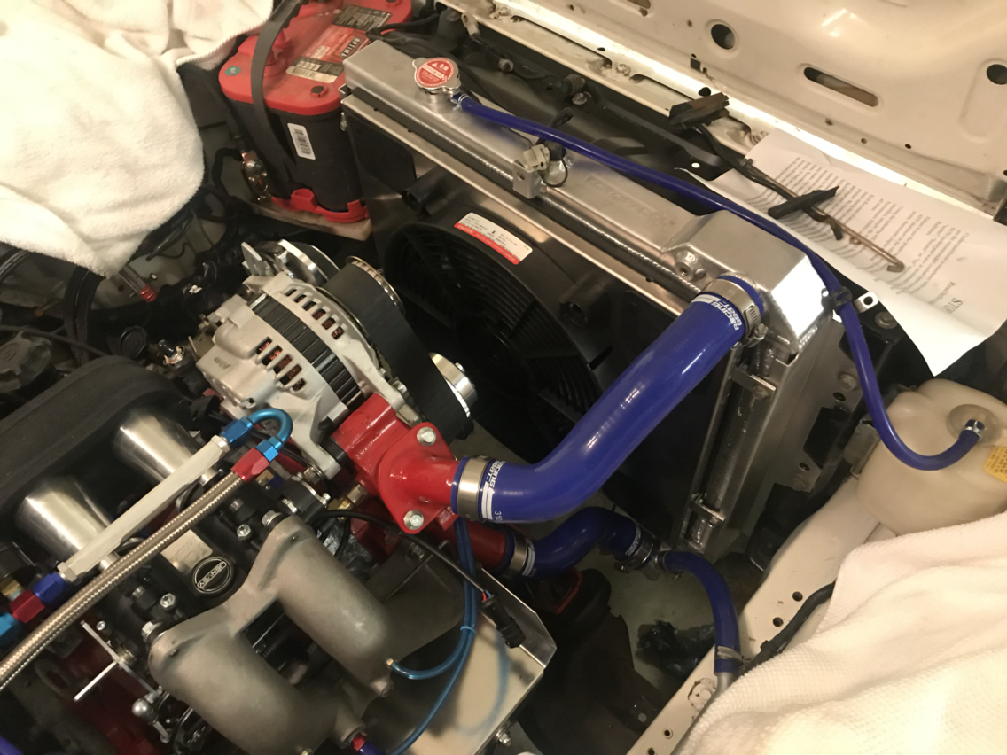
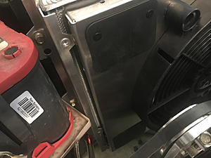
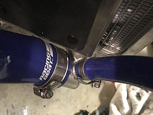
The fan is made by Derale but it's not fully installed yet. I dropped it in place yesterday just to make sure it was going to fit, but it's going to take a little creativity with the supplied brackets to secure it in place. It's also very close to the heater return neck, I may end up trimming some of the shroud. I'll post pics and details once I've finalized everything.
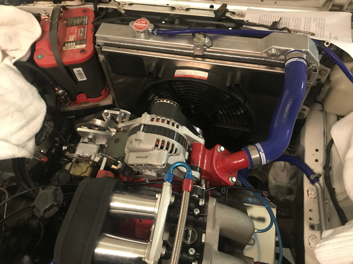
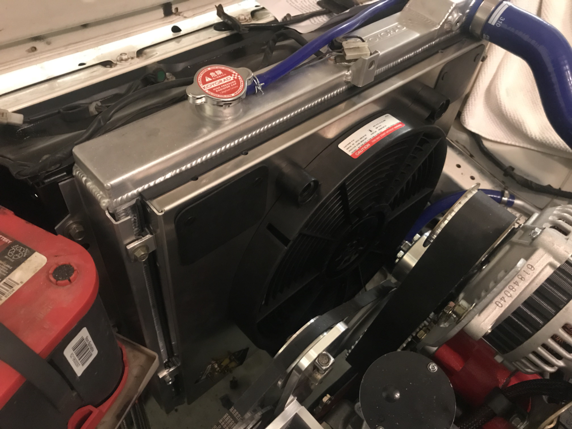
So this is the fan kit I bought.
https://www.summitracing.com/parts/DER-66820
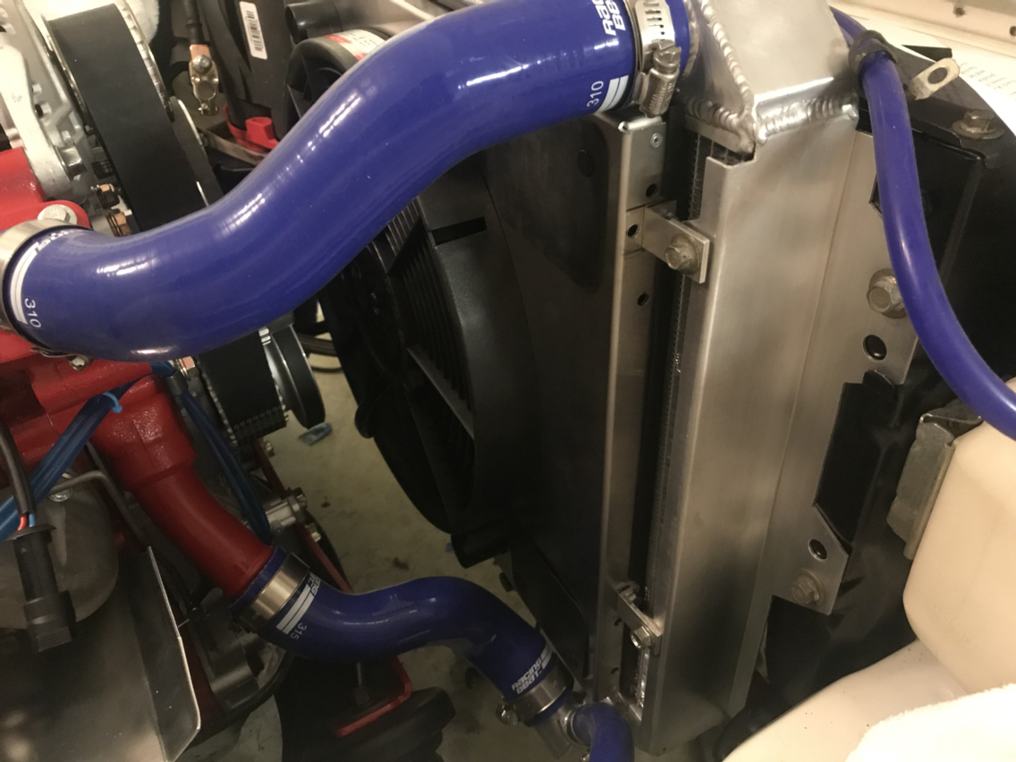
The fit is "snug" and I still need to work out mounting brackets. I'm also thinking about rotating it 180 degrees to place the control module closer to the battery. I may cut up the corner nearest the return neck because I'm not comfortable with how close it is...or I could trim the top edge so i can mount it higher and still have it sit flush. Decisions decisions.
https://www.summitracing.com/parts/DER-66820
The fit is "snug" and I still need to work out mounting brackets. I'm also thinking about rotating it 180 degrees to place the control module closer to the battery. I may cut up the corner nearest the return neck because I'm not comfortable with how close it is...or I could trim the top edge so i can mount it higher and still have it sit flush. Decisions decisions.


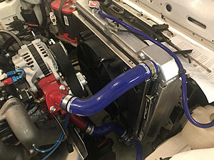
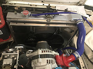
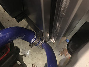
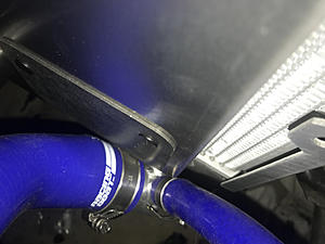
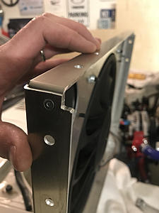
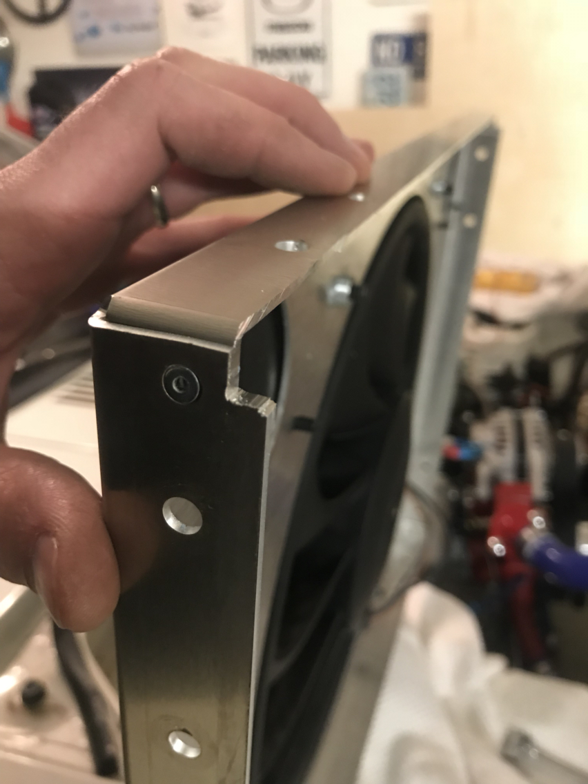
Decided to flip it.
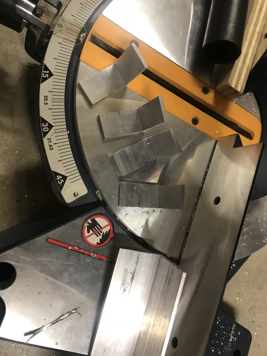
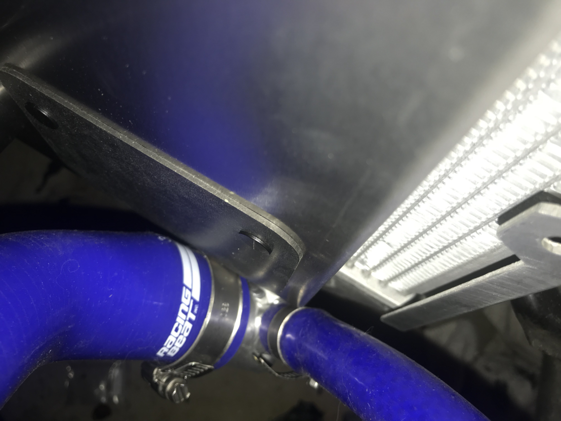
Drilled new holes for the upper flaps so they would hang right. Shaved off about 3/8" off the top so I could have it sit flush on the top and give more clearance below. Now I just need to figure out the brackets. Might start from scratch as the holes they gave me aren't going to work.
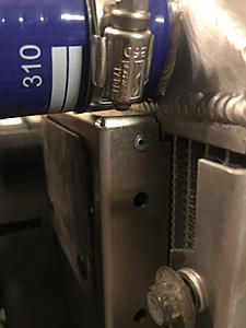
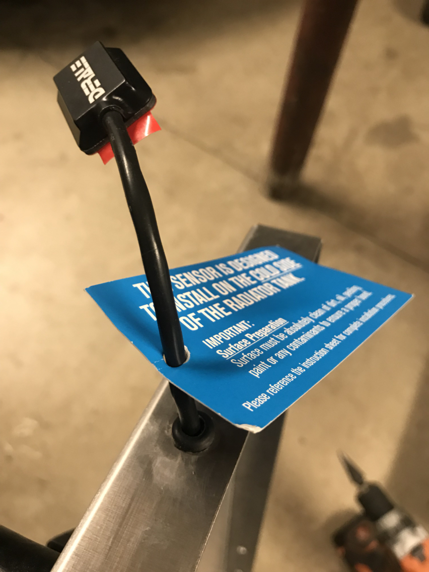
Ran the sensor inside the shroud to keep wires tidy. This will attach at bottom near the outlet.

Drilled new holes for the upper flaps so they would hang right. Shaved off about 3/8" off the top so I could have it sit flush on the top and give more clearance below. Now I just need to figure out the brackets. Might start from scratch as the holes they gave me aren't going to work.

Ran the sensor inside the shroud to keep wires tidy. This will attach at bottom near the outlet.