
79SA to 87EFI. Not nearly as simple as it looked.

frame & hoops by GySgtFrank, on Flickr Been a bit on updates. I have been working on it steadily. I got everything trial fitted only to find that my upper A arm mounts were an inch and a half too far back, oh well that's what trial fits are for. Pulled everything back apart and started clean up and final bracing. I put in frame hoops braced into the firewall. This will stiffen the frame and give me a solid foundation to hang the coil overs from. The driver's side was a little tricky as I had to incorporate a way to run the steering shaft through it (it's a leetle close). I also deleted the brake vacuum booster and incorporated the brake master cylinder mounting plate into the plate for the hoop. Far more compact mounting and should stiffen that up as well. I'll have to see how well the brakes work without it. Will finish doing my driver's side upper A arm mounts tomorrow. Then back to trial fitting and putting the K member back in. work, work, work.
Wow man keep it up! Inspiring work, whole other level!


Jiminy Christmas!
Definitely and ambitious build/learning tool. I would have never thought of using Mustang stuff.
I think I would have splayed those upper hoops in the engine compartment a little wider at the rear to accommodate the brake booster, but I like power brakes. My last manual brake car was my '70 Cutlass with manual DRUMS, so I may have a skewed lack of appreciation. I know plenty of racers and rodders run with manual disc brakes.
I'm planning on using the FC front subframe in my SA, but I was also planning on ZG flares, or the '79 IMSA bubbles if I can find them, so the increased track is not a problem. Wider wheels in the rear to make up the difference with the front. I'm impressed by your efforts to make it all fit under the stock sheetmetal, and now I'm very glad I won't have to!
Definitely subscribed!
^You don't need flares to fit an FC subframe and FC offset wheels in an FB fyi. Not saying you shouldn't get flares, but you don't need to necessarily
I agree, this is a very ambitious project - I'm looking forward to updates.
I agree, this is a very ambitious project - I'm looking forward to updates.
Thread Starter
Joined: Dec 2010
Posts: 645
Likes: 196
From: Stafford, Ks.
Jiminy Christmas!
Definitely and ambitious build/learning tool. I would have never thought of using Mustang stuff.
I think I would have splayed those upper hoops in the engine compartment a little wider at the rear to accommodate the brake booster, but I like power brakes. My last manual brake car was my '70 Cutlass with manual DRUMS, so I may have a skewed lack of appreciation. I know plenty of racers and rodders run with manual disc brakes.
I'm planning on using the FC front subframe in my SA, but I was also planning on ZG flares, or the '79 IMSA bubbles if I can find them, so the increased track is not a problem. Wider wheels in the rear to make up the difference with the front. I'm impressed by your efforts to make it all fit under the stock sheetmetal, and now I'm very glad I won't have to!
Definitely subscribed!
Definitely and ambitious build/learning tool. I would have never thought of using Mustang stuff.
I think I would have splayed those upper hoops in the engine compartment a little wider at the rear to accommodate the brake booster, but I like power brakes. My last manual brake car was my '70 Cutlass with manual DRUMS, so I may have a skewed lack of appreciation. I know plenty of racers and rodders run with manual disc brakes.
I'm planning on using the FC front subframe in my SA, but I was also planning on ZG flares, or the '79 IMSA bubbles if I can find them, so the increased track is not a problem. Wider wheels in the rear to make up the difference with the front. I'm impressed by your efforts to make it all fit under the stock sheetmetal, and now I'm very glad I won't have to!
Definitely subscribed!
), with them any further in. It's going to be interesting enough trying that one as it is. Keeping the bars straight also increases strength. Planning to use a bolt on cross bar to the center of the cowl and across the hoops to give me more bracing across the top of the engine bay.The FC subframe makes more sense for a quick and simple upgrade. I wanted to get rid of the MacPherson strut though and the SN95 spindles are a lot tougher with better aftermarket parts availability.
The FB does look good with the proper flares, not to mention easier, but I was trying for something a little different and thought, "Why not?".
I'm hoping that with the amount of braking surface and the large piston master cylinder in a car this light, that manual brakes won't be too bad. If I'm wrong I'll just have to fabricate something else up that gives me the room I need I guess.

Not knocking your work at all. I've got to keep it fairly simple if I have any hope of finishing!
I definitely like that you're attempting to keep it all under stock sheetmetal - that's just cool. I just happen to like the bubble flares. You're right, I bet you won't have too much trouble with the braking. With brakes that big, and under 3000 pounds, you'll probably be fine. If not, stick in a hydroboost!
I definitely like that you're attempting to keep it all under stock sheetmetal - that's just cool. I just happen to like the bubble flares.
You're right, I bet you won't have too much trouble with the braking. With brakes that big, and under 3000 pounds, you'll probably be fine. If not, stick in a hydroboost!
Thread Starter
Joined: Dec 2010
Posts: 645
Likes: 196
From: Stafford, Ks.
I didn't take it as knocking my work. Even for those that do mean it that way and can't understand why, it doesn't bother me. I'm doing this mainly for the fun of figuring it all out. It's more amusing than most people's obsessions.
The FC sub frame swap is definitely a whole lot simpler and most likely nearly or just as effective as the double A arm suspension for the majority of people. The biggest trick is properly locating the lower cradle and the strut tops so that the tire is centered in the wheel wells and correct caster is maintained. Camber adjustability is semi important too. Alex, (Whizbang), is one of the resident experts on this swap. I think he even swapped one under his bed so he can be near one at all times.
I needed the room though and every time I tried stuffing a wide tire under there, them dratted struts were right in the way. Break out fire wrench and voila, lots of room, ... and lots of work trying to put it back together.
I like the look of the bubble flares as well. I was planning for tires wider than flares can easily accommodate and a larger tire diameter though. The diameter change was going to require some work to maintain suspension travel anyway while maintaining a low ride height. That's if I wanted to actually run the car hard in the corners. I'm not an admirer of rock hard suspension set ups just to keep tires from rubbing/bottoming out. That's kind of a Band-Aid approach IMO.
I seriously considered going with a wide body kit of some kind. I've done one before on a Mustang and wasn't that thrilled with the modified look after a few years. I thought I'd try it this way on the RX-7 instead.
The FC sub frame swap is definitely a whole lot simpler and most likely nearly or just as effective as the double A arm suspension for the majority of people. The biggest trick is properly locating the lower cradle and the strut tops so that the tire is centered in the wheel wells and correct caster is maintained. Camber adjustability is semi important too.
Alex, (Whizbang), is one of the resident experts on this swap. I think he even swapped one under his bed so he can be near one at all times. I needed the room though and every time I tried stuffing a wide tire under there, them dratted struts were right in the way. Break out fire wrench and voila, lots of room, ... and lots of work trying to put it back together.
I like the look of the bubble flares as well. I was planning for tires wider than flares can easily accommodate and a larger tire diameter though. The diameter change was going to require some work to maintain suspension travel anyway while maintaining a low ride height. That's if I wanted to actually run the car hard in the corners. I'm not an admirer of rock hard suspension set ups just to keep tires from rubbing/bottoming out. That's kind of a Band-Aid approach IMO.
I seriously considered going with a wide body kit of some kind. I've done one before on a Mustang and wasn't that thrilled with the modified look after a few years. I thought I'd try it this way on the RX-7 instead.
Manual Brakes
What makes manual brakes work is the pedal ratio. A typical power brake pedal will have a 2 to 1 ratio where as a manual brake pedal will have a 5 to 1 or higher ratio. The net effect is that a similar about of pressure on the pedal by the driver with either power/non-power brakes will stop a car with ease.
The master cylinder/calipers have to matches for good performance as well. The goal is to generate the most clamping force with a reasonable amount of foot pressure on the brake pedal. This is not necessarily gained by installing a larger diameter master cylinder. In fact a good starting point would be to use the master cylinder that the manufacturer used with the brake calipers that are being installed. If the master cylinder is too big the pedal will be too stiff, if the pedal is too soft or the travel is too long the master cylinder is too small.
I have been involved with manual brake conversion on a couple of FOX mustangs. If the correct pedal assembly and master cylinder(s) are used there is no real extra pedal effort required by the driver.
The are other factors too. The brake step up on this car will probably have larger diameter rotors than the stock FB or even FC brakes. Larger diameter brakes have more leverage over the wheel so they get more work done with the same/less effort.
There is an excellent book on the subject of brakes by Fred Puhn called the Brake Handbook. I recommend this for anyone doing custom brakes
Thread Starter
Joined: Dec 2010
Posts: 645
Likes: 196
From: Stafford, Ks.
What makes manual brakes work is the pedal ratio. A typical power brake pedal will have a 2 to 1 ratio where as a manual brake pedal will have a 5 to 1 or higher ratio. The net effect is that a similar about of pressure on the pedal by the driver with either power/non-power brakes will stop a car with ease.
The master cylinder/calipers have to matches for good performance as well. The goal is to generate the most clamping force with a reasonable amount of foot pressure on the brake pedal. This is not necessarily gained by installing a larger diameter master cylinder. In fact a good starting point would be to use the master cylinder that the manufacturer used with the brake calipers that are being installed. If the master cylinder is too big the pedal will be too stiff, if the pedal is too soft or the travel is too long the master cylinder is too small.
I have been involved with manual brake conversion on a couple of FOX mustangs. If the correct pedal assembly and master cylinder(s) are used there is no real extra pedal effort required by the driver.
The are other factors too. The brake step up on this car will probably have larger diameter rotors than the stock FB or even FC brakes. Larger diameter brakes have more leverage over the wheel so they get more work done with the same/less effort.
There is an excellent book on the subject of brakes by Fred Puhn called the Brake Handbook. I recommend this for anyone doing custom brakes
The master cylinder/calipers have to matches for good performance as well. The goal is to generate the most clamping force with a reasonable amount of foot pressure on the brake pedal. This is not necessarily gained by installing a larger diameter master cylinder. In fact a good starting point would be to use the master cylinder that the manufacturer used with the brake calipers that are being installed. If the master cylinder is too big the pedal will be too stiff, if the pedal is too soft or the travel is too long the master cylinder is too small.
I have been involved with manual brake conversion on a couple of FOX mustangs. If the correct pedal assembly and master cylinder(s) are used there is no real extra pedal effort required by the driver.
The are other factors too. The brake step up on this car will probably have larger diameter rotors than the stock FB or even FC brakes. Larger diameter brakes have more leverage over the wheel so they get more work done with the same/less effort.
There is an excellent book on the subject of brakes by Fred Puhn called the Brake Handbook. I recommend this for anyone doing custom brakes

Junior Member
Joined: Feb 2014
Posts: 7
Likes: 0
From: Lester, Mn
Very nice setup, I personally enjoy the muffler setup you have. I thought it was gonna be a bit much when you had pictures of it up in the air and mounted but it looks great when it is on the ground outside! Love it!
Thread Starter
Joined: Dec 2010
Posts: 645
Likes: 196
From: Stafford, Ks.
Thanks for the compliment. That's the theme that I'm trying to go with on this car. Lots of modification, but not really noticeable from the outside unless you know what you're looking at.
Thread Starter
Joined: Dec 2010
Posts: 645
Likes: 196
From: Stafford, Ks.
Time for a little catch up. OK. Plan 436. I ran out of letters a ways back and had to start numbering them.
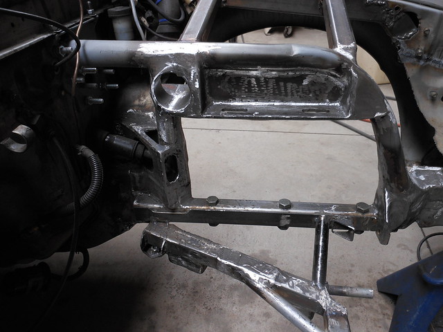
The lower rails are in. The lower rail is what the cradle will bolt to. The holes on the cradle will be slotted so I can adjust it forward and backward. When everything is this close I need to be able get the tire in the opening just right and this will help.
http://www.flickr.com/photos/gysgtfrank/12039158763/http://www.flickr.com/photos/gysgtfrank/12039158763/ by http://www.flickr.com/people/gysgtfrank/, on Flickr
and ... I screwed up again. The upper mounts were off by 1/2" on the driver's side and the passenger side was off by 3/4 - 1". I could have sworn I had them right that time, but it was not to be. I did have enough adjustment to get them where they needed to be (well within .2 degree on caster), but they were at the very end of the adjustment and then some. Not comfortable running it that way so here we go again. Trying to get an accurate measurement with very few squared up surfaces is a pain in the ***. So I need to cut them out one more time. Getting a little smarter this time and building a stand alone box for the mounts. That way I can bolt it in place and move the whole thing when I get the alignment equipment back on it.
Also did a little modification while the mounts are out. I didn't care much for the camber adjustment as it tended to move too far while adjusting and it was a pain to bring it back. So I drilled out the front holes and welded 1/2 - 20 nuts on them then put a cap and nut on the other side as well. That way I can run a fine thread 1/2" bolt in each side to push the mounting block back and forth for fine adjustment. It will also help lock it in place more securely.
http://www.flickr.com/photos/gysgtfrank/12227474796/http://www.flickr.com/photos/gysgtfrank/12227474796/ by http://www.flickr.com/people/gysgtfrank/, on Flickr
To fix the problem of being at the end of my adjustment range (and still being .2 degrees off in caster side to side). I came up with putting an adjustment rail on top of the camber adjustment rail. This necessitated raising the mounting point and opening up some more room to the rear. I'm using stop bolts on both sides of the clamping rails so I hopefully get no movement from my adjusters when under load. This is in addition to the bolts that clamp it all together. I have been a little concerned to make doubly sure I get no movement once I get the @#$%^ thing adjusted to the correct spot.
You can see the brackets for the lower cradle adjustments at the front of the lower rail. I'm in the process of welding in a plate to close up the top of the mount with the upper hoop and put some gusseting across it so that the mount is rock steady.
Not the most elegant solution, but I will have full fine adjustability to dial it in, as well as the ability to make large adjustments when I decide to do something stupid. Such as playing with my wheelbase.
Getting the car to DGRR is starting to look pretty iffy.
http://www.flickr.com/photos/gysgtfrank/12847426843/http://www.flickr.com/photos/gysgtfrank/12847426843/ by http://www.flickr.com/people/gysgtfrank/, on Flickr
Thread Starter
Joined: Dec 2010
Posts: 645
Likes: 196
From: Stafford, Ks.
Yes I'm still working on this. It's a good thing it's still not on it's wheels and I live in Kansas. Can't roll it around and can't find a cliff high enough to push it off of.
Definitely not getting the car to DGRR, but I plan to go anyway. So if you someone thumbing on the dragon it just may be me.
updates:
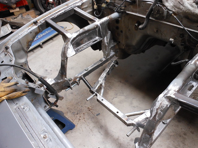
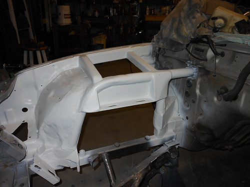
Reinforcements in and cleaned up the mounts. I had to put in a pass through hole on the driver's side for brake lines and wiring harness routing.

filled and ground 1 by GySgtFrank, on Flickr
filled and ground 2 by GySgtFrank, on Flickr
filled and ground 3 by GySgtFrank, on Flickr
filled and ground 4 by GySgtFrank, on Flickr
I have the wheel well mostly closed up on the driver's side. Much metal work, welding and grinding. Progress is still being made though. Just not quickly.
I purchased a pair of crusty old inner fenders for a '66 Galaxy wagon from the local salvage yard. It only took me about 7 hours to get the blankedy blank things out of the car. I'm hoping that they saved me enough metal forming time to make them worth it.

fender wells by GySgtFrank, on Flickr
The left front arch is in.
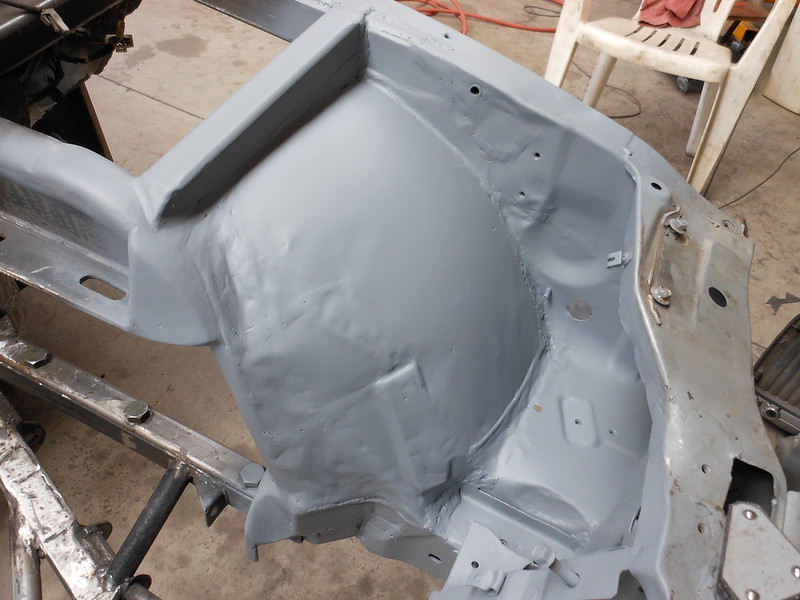
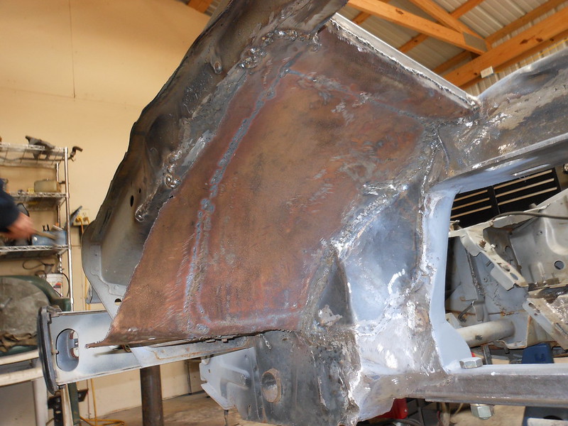
Rear portion of the driver's side wheel well done. It was a pain as I had to make it from small sections of flat sheet, heat and bend them, then weld the whole mess in. The welds are smoothed and I have primer on it anyway.
The portion from the Galaxy fender well wouldn't work as I had to form a pocket in exactly the right shape so that I had enough clearance to get my brake and clutch master cylinders in and out of there while maintaining as much tire clearance as possible. I should be able to use more of the wells on the passenger side as I don't have to worry about clearances over there as much.
Right now I'm busy modifying the original plastic inner fender liner to work with the new larger wheel wells. Then on to the other side.
Definitely not getting the car to DGRR, but I plan to go anyway. So if you someone thumbing on the dragon it just may be me.
updates:
Reinforcements in and cleaned up the mounts. I had to put in a pass through hole on the driver's side for brake lines and wiring harness routing.
filled and ground 1 by GySgtFrank, on Flickr
filled and ground 2 by GySgtFrank, on Flickr
filled and ground 3 by GySgtFrank, on Flickr
filled and ground 4 by GySgtFrank, on Flickr
I have the wheel well mostly closed up on the driver's side. Much metal work, welding and grinding. Progress is still being made though. Just not quickly.
I purchased a pair of crusty old inner fenders for a '66 Galaxy wagon from the local salvage yard. It only took me about 7 hours to get the blankedy blank things out of the car. I'm hoping that they saved me enough metal forming time to make them worth it.
fender wells by GySgtFrank, on Flickr
The left front arch is in.
Rear portion of the driver's side wheel well done. It was a pain as I had to make it from small sections of flat sheet, heat and bend them, then weld the whole mess in. The welds are smoothed and I have primer on it anyway.
The portion from the Galaxy fender well wouldn't work as I had to form a pocket in exactly the right shape so that I had enough clearance to get my brake and clutch master cylinders in and out of there while maintaining as much tire clearance as possible. I should be able to use more of the wells on the passenger side as I don't have to worry about clearances over there as much.
Right now I'm busy modifying the original plastic inner fender liner to work with the new larger wheel wells. Then on to the other side.

I'm not worthy! That's a fantastic job! I love the fact that you've repurposed old Galaxie inner fenders into this. Awesome. I wish my welds were like this, but sadly they are not. You've done an amazing job and I can't wait to see it with the suspension and wheels on sitting on the ground. It's gonna be even more impressive. Bravo to you Sir!
Thread Starter
Joined: Dec 2010
Posts: 645
Likes: 196
From: Stafford, Ks.
I'm not worthy! That's a fantastic job! I love the fact that you've repurposed old Galaxie inner fenders into this. Awesome. I wish my welds were like this, but sadly they are not. You've done an amazing job and I can't wait to see it with the suspension and wheels on sitting on the ground. It's gonna be even more impressive. Bravo to you Sir!
But I've been told I'm not the sharpest pencil in the cup before.
Thread Starter
Joined: Dec 2010
Posts: 645
Likes: 196
From: Stafford, Ks.
 Is yours being a PITA too?
I lost a seal on the front rotor in December, and I saw that as an opportunity rather than a bad thing- I parted it out, sold my Ford Ranger, and bought a sports car that was both fast and reliable I plan on getting an FD in the next year or two. Plus I picked up this GSL SE about 2 weeks before the engine went on the FC, it should hold me over.
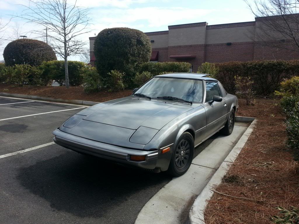
I plan on getting an FD in the next year or two. Plus I picked up this GSL SE about 2 weeks before the engine went on the FC, it should hold me over.
Thread Starter
Joined: Dec 2010
Posts: 645
Likes: 196
From: Stafford, Ks.
Sorry to hear about the FC. Personally I'd just keep the SE and play with that. Lots less money than an FD and about 400lbs. lighter. They also don't seem to have the same garage fetish as the FD.
Thread Starter
Joined: Dec 2010
Posts: 645
Likes: 196
From: Stafford, Ks.
After getting sidetracked with an *ahem* @#$% GM product for a while after DGRR, I have gotten back on it and have made a little more progress.
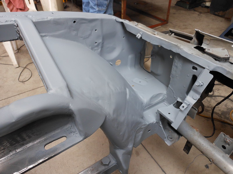
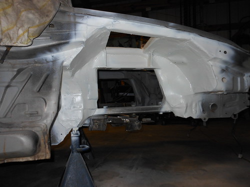
Finally done with the grinding on the left side and threw a quick coat of primer on there. I can no longer get the good 3M etching primer here, so I had to make do with Krylon. Which is why there is a color change in my primer.
Oh well. I'm not going to get carried away with paint yet. A good rattle can job will do in the engine bay until I'm done with the engine and all likely mods. I'll then have everything media blasted and use filler (or lead?) to smooth everything out prior to laying on the actual finish coat.
 left wheel well 1 by GySgtFrank, on Flickr
 left wheel well 2 by GySgtFrank, on Flickr
 left wheel well 3 by GySgtFrank, on Flickr
 left wheel well 4 by GySgtFrank, on Flickr
... and a shot of both wheel wells done and in primer. It's amazing how much faster and easier it always is to tear stuff apart rather than putting it back together again.
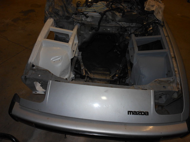 left and right wheel wells by GySgtFrank, on Flickr
I still have to do a little cleanup on the bottom of the right side and get it in primer, then I'll be finished with the sheet metal portion. Then back to the lower K-member/upper shock mounts. *groan* I have to put it all back together again. at least once and probably more, just to check measurements and then take it all back apart again for final fixes to both.
Yes I will get this done this year. At least until I tear something else apart and have it laying in pieces again. I suffer from a little recognized malady known as CQFWI (Can't Quit F***ing With It).
Finally done with the grinding on the left side and threw a quick coat of primer on there. I can no longer get the good 3M etching primer here, so I had to make do with Krylon. Which is why there is a color change in my primer.
Oh well. I'm not going to get carried away with paint yet. A good rattle can job will do in the engine bay until I'm done with the engine and all likely mods. I'll then have everything media blasted and use filler (or lead?) to smooth everything out prior to laying on the actual finish coat.
left wheel well 1 by GySgtFrank, on Flickrleft wheel well 2 by GySgtFrank, on Flickrleft wheel well 3 by GySgtFrank, on Flickrleft wheel well 4 by GySgtFrank, on Flickr... and a shot of both wheel wells done and in primer. It's amazing how much faster and easier it always is to tear stuff apart rather than putting it back together again.
left and right wheel wells by GySgtFrank, on FlickrI still have to do a little cleanup on the bottom of the right side and get it in primer, then I'll be finished with the sheet metal portion. Then back to the lower K-member/upper shock mounts. *groan* I have to put it all back together again. at least once and probably more, just to check measurements and then take it all back apart again for final fixes to both.
Yes I will get this done this year. At least until I tear something else apart and have it laying in pieces again. I suffer from a little recognized malady known as CQFWI (Can't Quit F***ing With It).
Seriously, this is an awesome build and I can't wait to see it on the road. It's gonna be one heck of a machine - a wolf in sheeps clothing. Good job Gunny!
Thread Starter
Joined: Dec 2010
Posts: 645
Likes: 196
From: Stafford, Ks.
Mostly I say "oww!"
Thread Starter
Joined: Dec 2010
Posts: 645
Likes: 196
From: Stafford, Ks.
In the continuing saga of the silly old bastard trying stupid stuff out in the shop ...
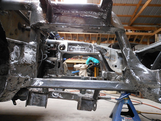
Another not so big surprise when I pulled the lower subframe and put it on a jig. After all of my fiddling and mods it was utterly dic*** up. After staring at it in disgust for quite a while I figured it would be easier just to build a new subframe than try to fix this one yet again.
For those interested in exactly what idiotic plan I have in mind to build a new lower subframe.
I set up a jig of the frame rails on my welding bench and did a solid tack on 1/4" thick 1.5" angle for the base. I'm using schedule 40 pipe (.2" thick) and cutting out 1/4" rounds with the proper 5/8" center holes to make up the A arm mounts. I had to have something to keep the arms in alignment as I moved it around to get the proper inward and downward angles. Welded the first one down and am building a front support piece from 3/16" plate. Then I have to figure out how to mirror all the angles and distances on the other side. Once both sides are in and correct, I will weld in the cross brace and studs to support the steering rack. I figure I can cut away the unneeded excess when everything is solid. That's the plan anyway.
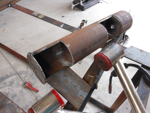 lower subframe version 2.0 by GySgtFrank, on Flickr
supports in and boxed.
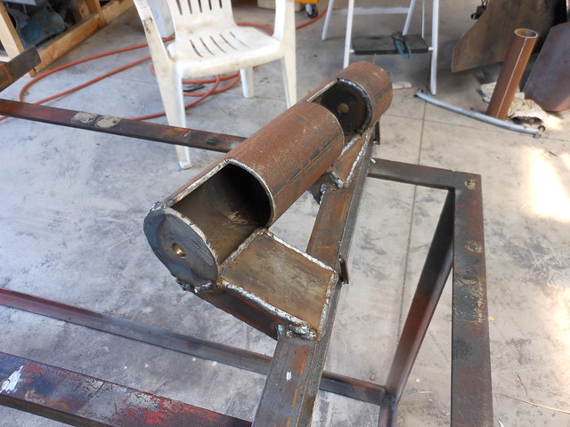 supports in and boxed by GySgtFrank, on Flickr
... a few moons, burns and cursing later ...
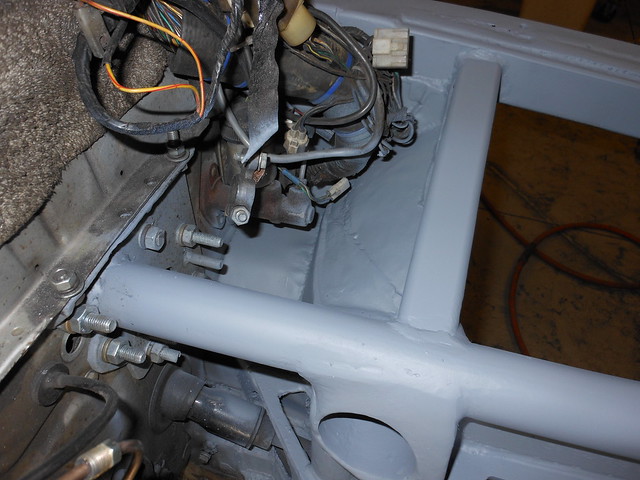
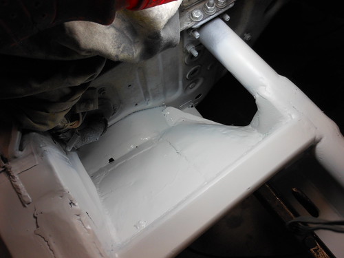
Mostly together. Clearancing the steering rack has been a bit of a PITA. I had to keep nibbling away at the side where the steering shaft goes to get enough room, without going too far. The rack had to come down far enough that the plane of the tie rods was in line with the A arm pivots (as well as centered, with the tie rod pivot points in line with the A arm pivot points, of course). If these angles and pivots aren't pretty damn close you will have bump steer problems. I barely had enough room to make that happen.
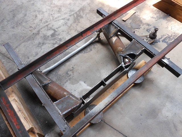 steering rack clearancing 1 by GySgtFrank, on Flickr
... and a shot of the steering rack sitting up against the mounting plate in it's proper position. As you can see, close, damn close.
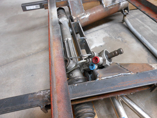 steering rack clearancing 2 by GySgtFrank, on Flickr
I still have to weld in the mounting studs for the rack and close up the gaping holes I made for clearance. I should be done with the steering rack at that point, ... I hope.
Another not so big surprise when I pulled the lower subframe and put it on a jig. After all of my fiddling and mods it was utterly dic*** up. After staring at it in disgust for quite a while I figured it would be easier just to build a new subframe than try to fix this one yet again.
For those interested in exactly what idiotic plan I have in mind to build a new lower subframe.
I set up a jig of the frame rails on my welding bench and did a solid tack on 1/4" thick 1.5" angle for the base. I'm using schedule 40 pipe (.2" thick) and cutting out 1/4" rounds with the proper 5/8" center holes to make up the A arm mounts. I had to have something to keep the arms in alignment as I moved it around to get the proper inward and downward angles. Welded the first one down and am building a front support piece from 3/16" plate. Then I have to figure out how to mirror all the angles and distances on the other side. Once both sides are in and correct, I will weld in the cross brace and studs to support the steering rack. I figure I can cut away the unneeded excess when everything is solid. That's the plan anyway.
lower subframe version 2.0 by GySgtFrank, on Flickrsupports in and boxed.
supports in and boxed by GySgtFrank, on Flickr... a few moons, burns and cursing later ...
Mostly together. Clearancing the steering rack has been a bit of a PITA. I had to keep nibbling away at the side where the steering shaft goes to get enough room, without going too far. The rack had to come down far enough that the plane of the tie rods was in line with the A arm pivots (as well as centered, with the tie rod pivot points in line with the A arm pivot points, of course). If these angles and pivots aren't pretty damn close you will have bump steer problems. I barely had enough room to make that happen.
steering rack clearancing 1 by GySgtFrank, on Flickr... and a shot of the steering rack sitting up against the mounting plate in it's proper position. As you can see, close, damn close.
steering rack clearancing 2 by GySgtFrank, on FlickrI still have to weld in the mounting studs for the rack and close up the gaping holes I made for clearance. I should be done with the steering rack at that point, ... I hope.