1984 5-letter / S5 "Selene"


 01-06-14, 03:25 AM
#157
Deep in the flow on the MSIII & FC ignition install and tuck.
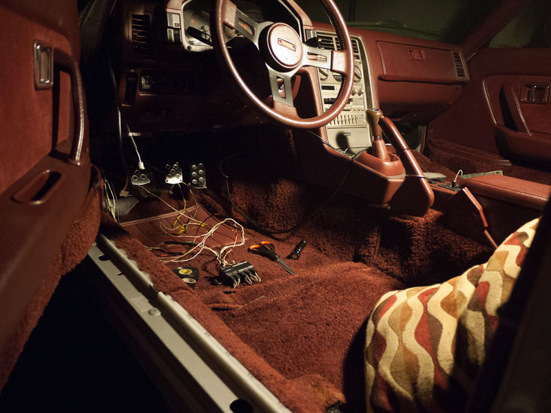
I've finally given up on the idea of keeping the air conditioner, and pulled the main unit from under the dash.
I used to have a sort of sentimental attachment to it, a creature-comfort that was top-of-the-line, factory installed on this premium GSL-SE. and anyways it already had the unit, condenser, and hard lines, all it needed was the pump. Why get rid of a system that was meant to be there?
Well, in my quest for the most optimal NA/FB configuration, I've already had to ditch the condenser to fit the cold air induction. I then decided to move the radiator overflow bottle up there as well to clean up the engine bay. Yet I was still not convinced to ditch the whole thing. Surely there was some way to retrofit some small form-factor, aftermarket condenser into the OEM system?
*Sigh,* this was starting to sound rare and expensive, two things I don't want to be building into my car.
I came to a realization - honestly, the only reason I would keep A/C in the car would be to keep a lady comfy. But ladies prefer to be warm, not cold. And when ladies are warm, they wear less clothing. I would prefer ladies that wear less clothing. No need for AC.
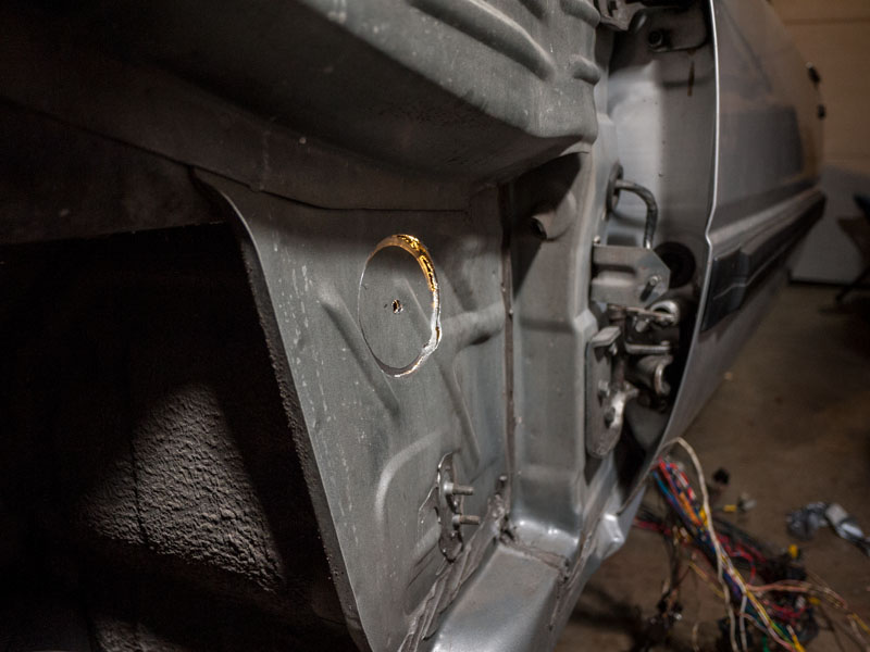
Today when I pulled off the driver-side wheel, fender liner, fender, and headlight for the tuck, I found there are handy holes along the entire length of the fender bracing, almost as if specifically made for wire harness plugs. And, as it turns out, I have a bunch of these plugs left over from where the harness connected on the inside of the engine bay
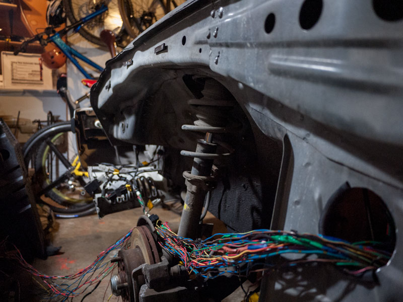
Also pulled out the main ground and power wires. These OEM wires be crimpin my style.
The new starter line will drop down to the frame rail and back to the firewall, across to the starter. The ground wire will drop off the front of the battery, tuck under the battery tray, back the frame rail, grounding out at the strut tower ps cooling line bolt. From here under and across to the rear iron of the engine block. My hope here is that it will better ground out the block, intake, and related ECU sensors, rather than dangling off the back of the starter bolt as was previously.
I will also run another 10ga ground wire back through the fender and across to the ECU. It's best to keep related systems powered and grounded on the same circuit, to isolate and reduce ground loops.
This past week I pulled the engine harness back into the cabin for the wire tuck. I found that the harness that wraps around the nose and back the passenger side fender is the ignition system harness, terminating at the 6-pin connector on the passenger side firewall. It connects into the main harness via a thick 12v black/white stripe and a yellow/green stripe tach signal from the trailing coil.
Since I'm installing an FC direct fire ignition with a standalone computer to control it, this entire harness can be removed. I pulled the thick 12v back into the cabin to hook up to additional hardware such as gauges, ECU, and related relays. Pretty sure it goes back to the fusible links as 12v constant, but I could be mistaken.
Tomorrow I will scope out some firewall grommets for the fender hole, and then buy a large-diameter circular drill bit to match. I need to pull through the stereo power wire as well, which I definitely want to isolate from the rest of the harness.
That's all for now, pictures after the break.
~Geoff
I've finally given up on the idea of keeping the air conditioner, and pulled the main unit from under the dash.
I used to have a sort of sentimental attachment to it, a creature-comfort that was top-of-the-line, factory installed on this premium GSL-SE. and anyways it already had the unit, condenser, and hard lines, all it needed was the pump. Why get rid of a system that was meant to be there?
Well, in my quest for the most optimal NA/FB configuration, I've already had to ditch the condenser to fit the cold air induction. I then decided to move the radiator overflow bottle up there as well to clean up the engine bay. Yet I was still not convinced to ditch the whole thing. Surely there was some way to retrofit some small form-factor, aftermarket condenser into the OEM system?
*Sigh,* this was starting to sound rare and expensive, two things I don't want to be building into my car.
I came to a realization - honestly, the only reason I would keep A/C in the car would be to keep a lady comfy. But ladies prefer to be warm, not cold. And when ladies are warm, they wear less clothing. I would prefer ladies that wear less clothing. No need for AC.
Today when I pulled off the driver-side wheel, fender liner, fender, and headlight for the tuck, I found there are handy holes along the entire length of the fender bracing, almost as if specifically made for wire harness plugs. And, as it turns out, I have a bunch of these plugs left over from where the harness connected on the inside of the engine bay
Also pulled out the main ground and power wires. These OEM wires be crimpin my style.
The new starter line will drop down to the frame rail and back to the firewall, across to the starter. The ground wire will drop off the front of the battery, tuck under the battery tray, back the frame rail, grounding out at the strut tower ps cooling line bolt. From here under and across to the rear iron of the engine block. My hope here is that it will better ground out the block, intake, and related ECU sensors, rather than dangling off the back of the starter bolt as was previously.
I will also run another 10ga ground wire back through the fender and across to the ECU. It's best to keep related systems powered and grounded on the same circuit, to isolate and reduce ground loops.
This past week I pulled the engine harness back into the cabin for the wire tuck. I found that the harness that wraps around the nose and back the passenger side fender is the ignition system harness, terminating at the 6-pin connector on the passenger side firewall. It connects into the main harness via a thick 12v black/white stripe and a yellow/green stripe tach signal from the trailing coil.
Since I'm installing an FC direct fire ignition with a standalone computer to control it, this entire harness can be removed. I pulled the thick 12v back into the cabin to hook up to additional hardware such as gauges, ECU, and related relays. Pretty sure it goes back to the fusible links as 12v constant, but I could be mistaken.
Tomorrow I will scope out some firewall grommets for the fender hole, and then buy a large-diameter circular drill bit to match. I need to pull through the stereo power wire as well, which I definitely want to isolate from the rest of the harness.
That's all for now, pictures after the break.
~Geoff
01-10-14, 04:40 AM
#159
Might wanna tuck that in
I promised myself that this winter I would do a wire tuck.
I put it off as long as I could, made excuses on how I needed to wait until I got the new computer in, or until mercury hits retrograde.
Enough bullshitting, time to actually do it. Thanks to Dave and Jesus for all the inspiration and help!
3" hole drilled into the kick panel above the foot rest. (Note to self: buy that plug-in drill, batteries suck.) I used duct tape on the inside of the kick panel to catch dropped metal shards and the final 3" chunk.
I then took a dremel to the sharp edge and smoothed it down, then cut a bit of vacuum hose and made a temporary gromet. Eventually I'll make a more permanant setup with some split bike tubes covering top and bottom half, allowing a split down the center for the loom.
After spending all of today out and about gathering the electrical supplies, connectors, wires, terminals, etc that I would need for the tuck, I finally get into the flow at 9pm only to realize my wire crimps do not work for the non-insulated butt connectors I plan to use.
And nobody's open.
In a frantic dash, my roomie and I hit up Fred Myer, and they have the absolute junkiest piece possible. but i pay $14 for it anyways, grab a box of Bitter American session ale, and make for the door.
They worked even worse than I had imagined.
Not willing to give up after building so much momentum, i dug through the garage and found a crimp tool that had a solid non-ins crimp. Whew! Time to dive in.
Dave convinced me to switch out all the connectors to weather pack. they will last forever, and the crimping tool is SOLID. I figured if i'm going to be extending or crimping anyways, might as well do it right and do it once.
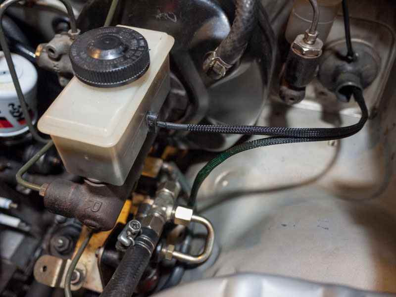
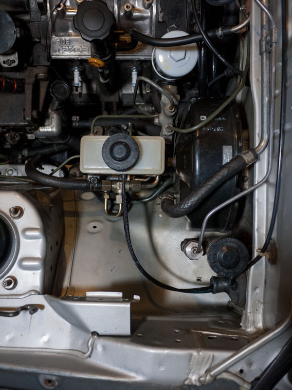
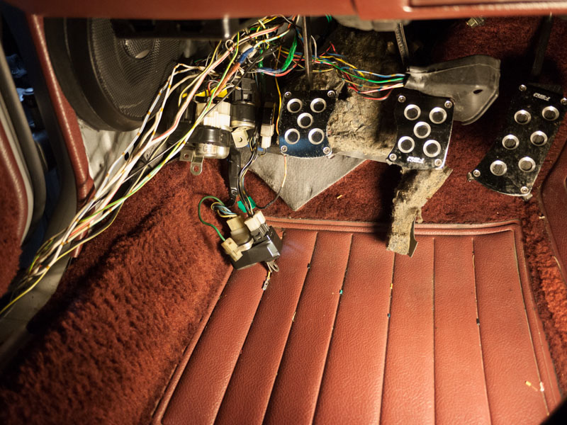
An extended and weather-packed brake fluid signal wire
The steering column wire joins the party
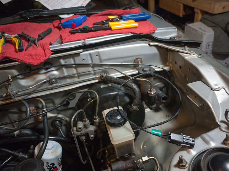
Looking so much better!
Time to get some rest and dive back in tomorrow.
I put it off as long as I could, made excuses on how I needed to wait until I got the new computer in, or until mercury hits retrograde.
Enough bullshitting, time to actually do it. Thanks to Dave and Jesus for all the inspiration and help!
3" hole drilled into the kick panel above the foot rest. (Note to self: buy that plug-in drill, batteries suck.) I used duct tape on the inside of the kick panel to catch dropped metal shards and the final 3" chunk.
I then took a dremel to the sharp edge and smoothed it down, then cut a bit of vacuum hose and made a temporary gromet. Eventually I'll make a more permanant setup with some split bike tubes covering top and bottom half, allowing a split down the center for the loom.
After spending all of today out and about gathering the electrical supplies, connectors, wires, terminals, etc that I would need for the tuck, I finally get into the flow at 9pm only to realize my wire crimps do not work for the non-insulated butt connectors I plan to use.
And nobody's open.
In a frantic dash, my roomie and I hit up Fred Myer, and they have the absolute junkiest piece possible. but i pay $14 for it anyways, grab a box of Bitter American session ale, and make for the door.
They worked even worse than I had imagined.
Not willing to give up after building so much momentum, i dug through the garage and found a crimp tool that had a solid non-ins crimp. Whew! Time to dive in.
Dave convinced me to switch out all the connectors to weather pack. they will last forever, and the crimping tool is SOLID. I figured if i'm going to be extending or crimping anyways, might as well do it right and do it once.
An extended and weather-packed brake fluid signal wire
The steering column wire joins the party
Looking so much better!
Time to get some rest and dive back in tomorrow.
01-10-14, 05:15 PM
#161
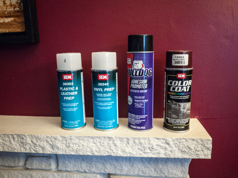
Forum member was asking about the interior resto, and I realized I never took a picture of the materials needed.
So here they are
The step by step is detailed here:
https://www.rx7club.com/build-thread.../#post11402688
Oh and another tip, when cleaning the panels make SURE to use a lint-free cloth!!!!! The rags that i used left micro fibers all over which got painted into the finish its not noticeable unless your face is right up innit, or if you're the one who did it so you notice every time.
So here they are
The step by step is detailed here:
https://www.rx7club.com/build-thread.../#post11402688
Oh and another tip, when cleaning the panels make SURE to use a lint-free cloth!!!!! The rags that i used left micro fibers all over which got painted into the finish
its not noticeable unless your face is right up innit, or if you're the one who did it so you notice every time.
01-11-14, 07:27 AM
#162
I've been missing out not being on the forums lately. Just went through your whole thread and loving the work your doing! Great job and looking forward to more updates! Makes me want to get in the garage and clean up some of the messes bothering me lol
01-12-14, 04:07 PM
#163
Thanks twinkletoes! Loving your build as well, thanks for the new pics, I'd love to get some hi-res versions of those for my collection.
---
Last night I finished up most of the driver's side harness tuck / extend. I've gone through 3 pairs of crimps trying to find the best ones for the solderless crimps i'm using. So far the $7 cheapos have the best/strongest crimp. The $14 ones have the best strippers, and i'm guessing the $20 "heavy duty" ones will be good for the battery cable.
I read in Aaron Cake's "How to Megasquirt your RX7" website that you should only use adhesive-lined heat shrink as normal heat shrink won't protect from moisture. Well, nobody in Seattle sells adhesive lined heat shrink, so i'm making do with what I've got.
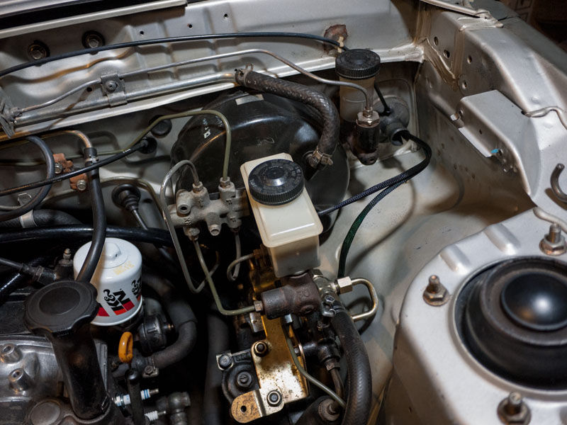
I re-did the power steering column wiring with some black heat shrink underneath, I wasn't down with the green-through-black look. Also tried a little experiment with the brake booster hose. Not sure if I like enough to do all the hoses under the hood, I'm thinking i should just leave them bare/clean rubber.
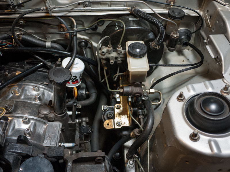
As I've been pulling everything out, I've been deep cleaning the engine bay. I'm employing the use of my Sonicare tooth brush - works GREAT for tight squeezes, behind the brake booster, in the corners, etc. However, nothing can re-apply corroded and stripped paint, and I've got quite a bit of that. Near the battery tray, driver strut tower, and behind / below the brake booster and clutch master.
While I had the headlight retractor out, I decided I might as well freshen up the wiring on that as well. For all the work, when I installed it I realized you can barely see it, but oh well at least its unique and I'LL know that I did it
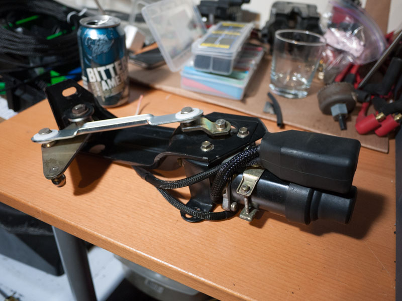
These photos aren't quite an accurate representation of the bay yet, as I still have to install the ignition. For now I'm going to work on a strut tower mount, and re-use my Magnecor R100's. When I get the rack & pinion installed (some distant time down the road, RE-Speed we miss you!) then I'll more than likely relocate the ignition down to the frame rail.
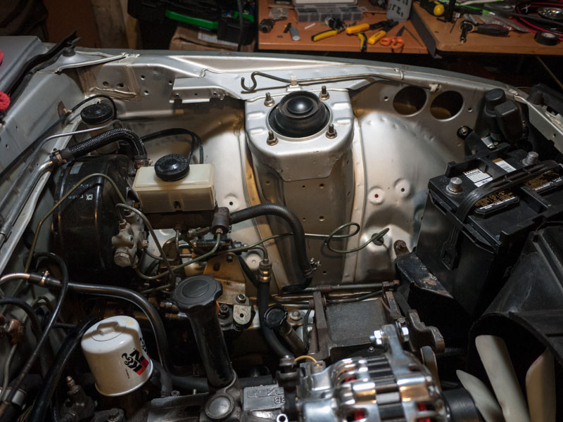
Right now I'm only re-wiring the OEM harness, which includes the lighting harness, radiator wires, horns, and retractor motors. After I've got all this rewired and tucked, then I'll route and install the Megasquirt harness, part of which will drop down the transmission tunnel to the block, and the other part will wrap around the driver fender up to the nose and back (for CAS) and out the factory harness grommet (for ignition)
---
Last night I finished up most of the driver's side harness tuck / extend. I've gone through 3 pairs of crimps trying to find the best ones for the solderless crimps i'm using. So far the $7 cheapos have the best/strongest crimp. The $14 ones have the best strippers, and i'm guessing the $20 "heavy duty" ones will be good for the battery cable.
I read in Aaron Cake's "How to Megasquirt your RX7" website that you should only use adhesive-lined heat shrink as normal heat shrink won't protect from moisture. Well, nobody in Seattle sells adhesive lined heat shrink, so i'm making do with what I've got.
I re-did the power steering column wiring with some black heat shrink underneath, I wasn't down with the green-through-black look. Also tried a little experiment with the brake booster hose. Not sure if I like enough to do all the hoses under the hood, I'm thinking i should just leave them bare/clean rubber.
As I've been pulling everything out, I've been deep cleaning the engine bay. I'm employing the use of my Sonicare tooth brush - works GREAT for tight squeezes, behind the brake booster, in the corners, etc. However, nothing can re-apply corroded and stripped paint, and I've got quite a bit of that. Near the battery tray, driver strut tower, and behind / below the brake booster and clutch master.
While I had the headlight retractor out, I decided I might as well freshen up the wiring on that as well. For all the work, when I installed it I realized you can barely see it, but oh well at least its unique and I'LL know that I did it
These photos aren't quite an accurate representation of the bay yet, as I still have to install the ignition. For now I'm going to work on a strut tower mount, and re-use my Magnecor R100's. When I get the rack & pinion installed (some distant time down the road, RE-Speed we miss you!) then I'll more than likely relocate the ignition down to the frame rail.
Right now I'm only re-wiring the OEM harness, which includes the lighting harness, radiator wires, horns, and retractor motors. After I've got all this rewired and tucked, then I'll route and install the Megasquirt harness, part of which will drop down the transmission tunnel to the block, and the other part will wrap around the driver fender up to the nose and back (for CAS) and out the factory harness grommet (for ignition)
01-13-14, 05:15 AM
#164
Awesome work! You pulled the dash for the wire tuck right? Your wiring work looks really fresh! I'm curious where you get your connectors, black wire sheild wrap, and other necessary items? Online or local stores? I'm planning a wire tuck next time my engine is out, but want to redo some connectors and wiring now on my harness that I never liked after it was installed originally.
01-15-14, 05:44 PM
#166
I left the dash in the car. There's only one spot where the factory harness goes up through the dash (over the stereo) and back down the other side, and you can disconnect it from the rest of the engine harness, let it just hang.
The connectors I got from EBay - search weatherpack kits. Get the big kit. I got the $70 kit and blew through that the first two nights of work. Luckily our buddy David had the full mega kit ($240) and let me borrow it, so i'm pulling from that kit and paying him per connector. They work out to be a buck or two a connection, ebay prices. The thing I like about the weatherpack connectors is they are almost a guaranteed solid crimp, with their specialty tool.
The sleeving and heat shrink i got from Vetco, a local(ish) electronics store, but they sell online as well: Vetco Electronics - www.vetco.net
I got my power, ground, and alternator wire (not yet run) from the local car audio shop. I decided to go with clear wires
Jesus - I decided to ditch the sleeving on the hoses. I did the brake booster and radiator overflow - it looked great, but not the look i'm going for right now, which is keep the natural patina of the oem parts, but keep them hella clean. Fortunately, my brake booster and overflow hoses are in good shape, and I'm replacing all the radiator and heater hoses with Mazda OEM today, so I'll just go for the fresh stock look.
01-17-14, 03:04 PM
#167
I left the dash in the car. There's only one spot where the factory harness goes up through the dash (over the stereo) and back down the other side, and you can disconnect it from the rest of the engine harness, let it just hang.
The connectors I got from EBay - search weatherpack kits. Get the big kit. I got the $70 kit and blew through that the first two nights of work. Luckily our buddy David had the full mega kit ($240) and let me borrow it, so i'm pulling from that kit and paying him per connector. They work out to be a buck or two a connection, ebay prices. The thing I like about the weatherpack connectors is they are almost a guaranteed solid crimp, with their specialty tool.
The sleeving and heat shrink i got from Vetco, a local(ish) electronics store, but they sell online as well: Vetco Electronics - www.vetco.net
I got my power, ground, and alternator wire (not yet run) from the local car audio shop. I decided to go with clear wires
I searched the weatherpack kits and will make a order today. I'm going to ask around with a few local people and see if I can find a local source for wire sleeving. Thanks for the info
01-17-14, 11:10 PM
#168
Great to hear on the wire tuck! Think this is the first one I've seen without the dash being pulled out. Even some of the Miata guys I know in town pull the dash for a full wire tuck. Seems to be a common thing.
I searched the weatherpack kits and will make a order today. I'm going to ask around with a few local people and see if I can find a local source for wire sleeving. Thanks for the info .
.
I searched the weatherpack kits and will make a order today. I'm going to ask around with a few local people and see if I can find a local source for wire sleeving. Thanks for the info
The only part of the harness you can't reach with the dash in is the loom that connects into the ECU harness, which is conveniently un-pluggable at the ecu. I haven't yet connected the power wires, so i'm as yet uncertain how much the ECU plays into the function of the rest of the car.
I have a suspicion that it does nothing at all (in terms of power steering, lights / blinkers, etc). But i'm thinking that even with the stock ECU you should be able to do a tuck without pulling the dash.
Through this process i've pondered doing a write up or how-to, however I don't think that would really be helpful for people. You really need to read through the wiring diagrams, observe the oem harness, and learn how it all connects together and works. Without that process of discovery and a strong confidence in your ability to wire or read diagrams, this is not a project someone should just follow a step-by-step and try for themselves.
That said, I will certainly compile a list of resources, links, diagrams, etc that i have discovered along the way.
On that note, this wiring tutorial has been blowing my mind. It describes how to set up a full-built power and ground circuit for the car, specifically for a battery relocation, but it also applies well to a wire tuck as you're extending several of the same wires. It also has the CORRECT wiring and explination for an FD (s6/s7) alternator upgrade:
AusRotary.com • View topic - MOVING A BATTERY FROM ENGINE BAY TO THE BOOT!!
01-22-14, 06:05 AM
#169
Today: wiring. Almost finished tidying up the fusible link and factory relay relocation to under dash. Running 4ga back from battery to links, then 8ga from links over to megasquirt.
Tested my proposed ground circuit along the driver frame rail - 0 ohm loss from engine-to-chassis ground point and battery ground point. Now that's what I'm talking about!
Will have all main grounds including dedicated 8ga ECU circuit ground tied in at the same battery-to-chassis point. Should be solid.
Decided to run 4ga wire from alternator to starter (+), then 4ga from there back to battery (+). Will simplify my whole power and charging circuit fourfold.
Ordered in a 4 position distro/relay block, which will fuse and distribute in front of the radiator to: headlight relay harness (30amp), e-fans (30ish amp), fusible links & megasquirt (100+ amp) and JL stereo amplifier (60amp).
Need to figure out what to do for fans for the new, smaller radiator. I've found some decent 10" Summit fans for around $60 each, with an 1,100cfm rating (each), which should be more than enough with the high efficiency alu radiator. Now the question is - pusher or puller I'd say pusher - no brainier, however with the cold air intake and radiator overflow up there, it'd be a squeeze.
Tomorrow: get the rest of the power and ground terminals and a thing of dielectric grease to put on top, then plug in the battery and see if this **** works!
Tested my proposed ground circuit along the driver frame rail - 0 ohm loss from engine-to-chassis ground point and battery ground point. Now that's what I'm talking about!
Will have all main grounds including dedicated 8ga ECU circuit ground tied in at the same battery-to-chassis point. Should be solid.
Decided to run 4ga wire from alternator to starter (+), then 4ga from there back to battery (+). Will simplify my whole power and charging circuit fourfold.
Ordered in a 4 position distro/relay block, which will fuse and distribute in front of the radiator to: headlight relay harness (30amp), e-fans (30ish amp), fusible links & megasquirt (100+ amp) and JL stereo amplifier (60amp).
Need to figure out what to do for fans for the new, smaller radiator. I've found some decent 10" Summit fans for around $60 each, with an 1,100cfm rating (each), which should be more than enough with the high efficiency alu radiator. Now the question is - pusher or puller
I'd say pusher - no brainier, however with the cold air intake and radiator overflow up there, it'd be a squeeze.Tomorrow: get the rest of the power and ground terminals and a thing of dielectric grease to put on top, then plug in the battery and see if this **** works!
 01-30-14, 12:20 AM
#171
Last Friday i plugged in the battery to test out the wire tuck so far - immediately blew the injection fusible link. I found this odd as I have removed most of the injection harness. In fact, all of it save for a few wires.
Checked and double checked the harness, everything looked clean. I then realized it was 2am when I tested it - weary and overly enthusiastic to see it work. I had left several wires dangling - even though they all had a clean cut or an insulated connector, one of them was obviously making contact.
Removed ALL old ECU wiring from the car, taped off any un-terminate wires, and voila no blown fuse.
Now I can solidify the relays and fusible link blocks (with FC style drop in fuses) and start wiring in the Megasquirt!
Final component is to get some fusible link wire in for the alternator wires, then wire in the megasquirt harness!
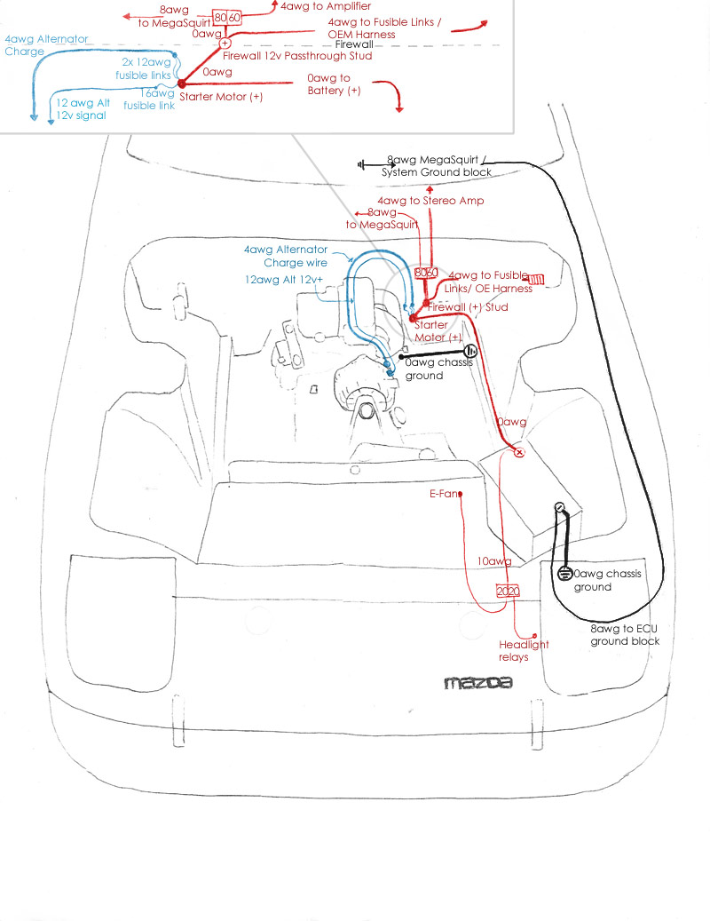
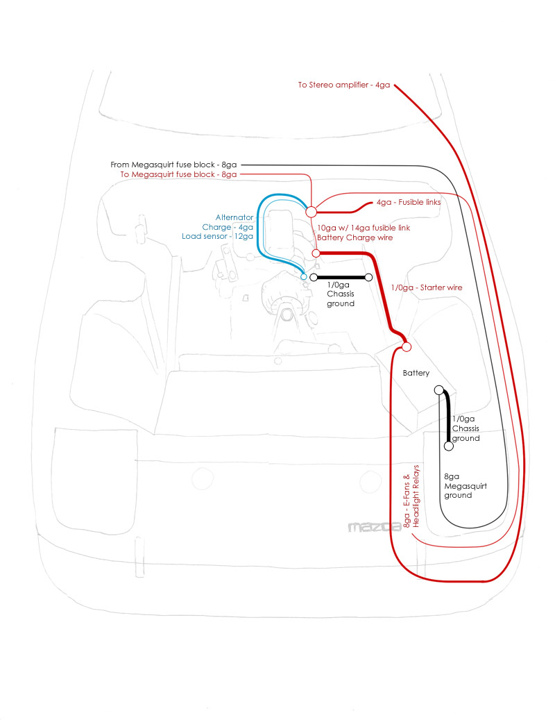
I've included a diagram of the power grid I'm building - I just got the insulated firewall lug for the 0gauge feed into the cabin, will put that in tonight. The only difference between this layout and the grid as its being installed is that I'm pulling the alternator and sensor wire to the firewall stud instead of the starter motor. I had to hella compress the image size to meet the forum requirements (i severely dislike this forum software and how they've chosen to configure it). Contact me for a hi-res version.
Bundling up the relays to tuck under the dash (fusible links are dangling out the door):
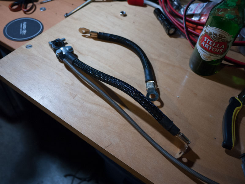
Fusible links ready to be plugged in and tested (make sure to put them in a plastic dish or something in case they blow - they may burn through the cloth insulation)
1/0 awg ground wires - the dual one goes from battery - to frame rail, then the 8awg wire goes up to the Megasquirt fuse / ground distro block. Other short length of 1/0 awg goes from rear iron starter motor bolt over to the frame rail where the power steering line bolt is.
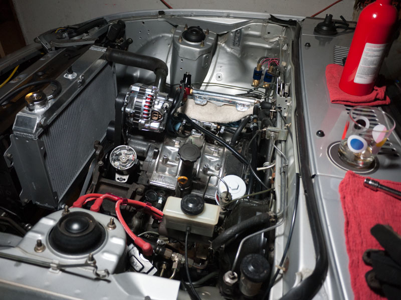
Progress so far (including shitty radiator that doesnt fit and won't accept any OEM sensors! bonus!)
Checked and double checked the harness, everything looked clean. I then realized it was 2am when I tested it - weary and overly enthusiastic to see it work. I had left several wires dangling - even though they all had a clean cut or an insulated connector, one of them was obviously making contact.
Removed ALL old ECU wiring from the car, taped off any un-terminate wires, and voila no blown fuse.
Now I can solidify the relays and fusible link blocks (with FC style drop in fuses) and start wiring in the Megasquirt!
Final component is to get some fusible link wire in for the alternator wires, then wire in the megasquirt harness!
I've included a diagram of the power grid I'm building - I just got the insulated firewall lug for the 0gauge feed into the cabin, will put that in tonight. The only difference between this layout and the grid as its being installed is that I'm pulling the alternator and sensor wire to the firewall stud instead of the starter motor. I had to hella compress the image size to meet the forum requirements (i severely dislike this forum software and how they've chosen to configure it). Contact me for a hi-res version.
Bundling up the relays to tuck under the dash (fusible links are dangling out the door):
Fusible links ready to be plugged in and tested (make sure to put them in a plastic dish or something in case they blow - they may burn through the cloth insulation)
1/0 awg ground wires - the dual one goes from battery - to frame rail, then the 8awg wire goes up to the Megasquirt fuse / ground distro block. Other short length of 1/0 awg goes from rear iron starter motor bolt over to the frame rail where the power steering line bolt is.
Progress so far (including shitty radiator that doesnt fit and won't accept any OEM sensors! bonus!)
01-30-14, 10:30 PM
#173
Corrected wiring diagram
So the above diagram was not finalized - and I knew that there were a couple of iffy things going on there.
One of the reasons I seriously dislike this forum is that you are not allowed to correct WRONG information, and often times that WRONG information is put into stickies, how-tos, or the archive. This is how SO MUCH BAD INFO is perpetuated, and I'll be the first to admit I've posted things on here that are flat-out wrong. I wish with all my heart i could go back and edit them to archive CORRECT and ACCURATE info, but alas it is against forum policy, because they think that editing a post will be used in childish bantering and prank situations. Its for these reasons I'm seriously considering no longer posting on this forum. Anyways, I digress...
I called up Mark @ MAD Enterprises to order some fusible link wire, and instead had a lengthy discussion of proper wiring of charging and power systems. He confirmed some of my suspicions, and dropped a HEAP of knowledge. I wish I had recorded the conversation.
I HIGHLY recommend that anyone altering or upgrading the charging or power system read through Mark's write up on old Chevy systems. Totally different system, but he covers a lot of ground on proper electrical system configurations and wiring. It's essential to understand these concepts to read through a lot of the BS that is out there, on the internet, even from your local rod shops. He makes some particularly interesting points about using wire resistance to your advantage on the charge wire to the battery - a trickle charge is much gentler on the battery (less off gassing, corrosion, etc) than a thick-gauge fast charging wire:
The Chevy Main Power Distribution, pt 1
The ideal charging system diagram is on page 2 in black titled "new system"
The Chevy Main Power Distribution, pt 2
Here are some of my notes, with the corrected (I dare not say finalized, as this is version 4 so far) wiring diagram.
===
First off - the basics of a power and charging system:
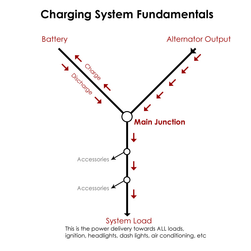
The battery is used almost exclusively during cranking of the starter motor, not to power accessories while the engine is running. The only exception to this would be running accessories while the car is off, powering the accessories for a split second when first turning them on, or when hooking a stereo amplifier up to the battery + terminal (more on this below).
The alternator output and sensor wire need to be connected at a main junction where ALL loads (except stereo amplifier) are to be pulled from. Further junctions can be added downstream, but the alternator must be wired in at the junction on the line that is closest to the battery, where the circuit will see the total system load.
In my install, the length of wire between the firewall stud and the starter motor will become the battery charge wire. The battery charge needs only about 30-40 amp continual draw, and that's in a 100% drained battery charging condition. As the battery is charged, the amperage draw will decrease to a no-load condition when full.
The main system power for all of the accessories is being generated almost exclusively by the alternator, not the battery. The exception to this would be the stereo amplifier.
STEREO AMPLIFIER power needs to be sourced via 4 gauge directly to the battery (+) terminal, and here's why: when the bass hits the amplifier will pull large amounts of amperage in very short duration of time, faster than the alternator can sense and output.
This is why audio shops (even Walmart these days) sell "stiffening capacitors," large capacitors you wire inline with the power feed to the amplifier to smooth out the amp draw from the main system load. It's basically a small battery that holds surplus charge that can be pulled at a moments notice without hitting the rest of the electrical system.
This is why you will want to pull the sound system power directly from the car battery - it will act as a stiffening capacitor and discharge current for those instantaneous bass hits, and as it is drained the alternator will sense the battery drawing a load and up its output to charge the battery back up. As the battery is otherwise only used for cranking (alternator is taking care of running the rest of the system), this is an ideal configuration.
A special note on S5/S6/S7 (FC, FD) alternator installs / swaps:
DO NOT loop the load sensing wire (top of the two wires on the FD alt) to the alternator output wire terminal. It will not properly detect load on the system, and the entire system will be pulling off the battery. The load sensing wire in this configuration will read that the output matches the load, so no additional charge will be output. The sensor wire needs to be at the MAIN load junction, where voltage drop will be accurate to all accessories powered. For an OEM FB, this would be at the fusible link block.
Also do not wire the sensor wire into the OEM fb black alternator wire, this is a 12v constant wire, even when the car is off. This will trigger the alternator to ramp up the amp output, even though the engine is not turning. Although the alternator isn't actually outputting that amperage difference, the fact that its engaging will cause a slight drain on the battery. Daily driven cars may not notice the drain, but if parked for extended periods this drain may be noticeable enough to cause slow or no-start conditions for the starter motor.
Additional notes of worth:
When stacking ring terminals - put largest loads directly on top of or below the feed or source. When stacking terminals, the electrons pass through the outer surface of the ring terminal, not through the threads of the stud.
Battery Surge - When turning accessories on or off, there will be a surge of power for an instant before the alternator can pick up the pace, this will be provided by the battery in a "discharge" surge. The largest surge of power will come from turning on the lights, NOT from an electric fan or any other accessory as many people may say. Each light, even the little ones in the dash, amount to a huge draw, and are all being activated at once. A headlight relay harness is an EXCELLENT idea for ANY car wiring, but particularly our FB's which source their power through the harness and combination switch itself!!!
Similarly, when powering OFF the system, the battery will receive a "charge" surge from the alternator before it can step down its output, which was previously at high amperage to power all the accessories. These are factors to consider when sizing your battery charge wire, although it wont be continually charging or discharging at these amperage values, it will be seeing these conditions regularly for split second intervals.
===
Revised power grid for FB wire tuck:
===
One of the reasons I seriously dislike this forum is that you are not allowed to correct WRONG information, and often times that WRONG information is put into stickies, how-tos, or the archive. This is how SO MUCH BAD INFO is perpetuated, and I'll be the first to admit I've posted things on here that are flat-out wrong. I wish with all my heart i could go back and edit them to archive CORRECT and ACCURATE info, but alas it is against forum policy, because they think that editing a post will be used in childish bantering and prank situations. Its for these reasons I'm seriously considering no longer posting on this forum. Anyways, I digress...
I called up Mark @ MAD Enterprises to order some fusible link wire, and instead had a lengthy discussion of proper wiring of charging and power systems. He confirmed some of my suspicions, and dropped a HEAP of knowledge. I wish I had recorded the conversation.
I HIGHLY recommend that anyone altering or upgrading the charging or power system read through Mark's write up on old Chevy systems. Totally different system, but he covers a lot of ground on proper electrical system configurations and wiring. It's essential to understand these concepts to read through a lot of the BS that is out there, on the internet, even from your local rod shops. He makes some particularly interesting points about using wire resistance to your advantage on the charge wire to the battery - a trickle charge is much gentler on the battery (less off gassing, corrosion, etc) than a thick-gauge fast charging wire:
The Chevy Main Power Distribution, pt 1
The ideal charging system diagram is on page 2 in black titled "new system"
The Chevy Main Power Distribution, pt 2
Here are some of my notes, with the corrected (I dare not say finalized, as this is version 4 so far) wiring diagram.
===
First off - the basics of a power and charging system:
The battery is used almost exclusively during cranking of the starter motor, not to power accessories while the engine is running. The only exception to this would be running accessories while the car is off, powering the accessories for a split second when first turning them on, or when hooking a stereo amplifier up to the battery + terminal (more on this below).
The alternator output and sensor wire need to be connected at a main junction where ALL loads (except stereo amplifier) are to be pulled from. Further junctions can be added downstream, but the alternator must be wired in at the junction on the line that is closest to the battery, where the circuit will see the total system load.
In my install, the length of wire between the firewall stud and the starter motor will become the battery charge wire. The battery charge needs only about 30-40 amp continual draw, and that's in a 100% drained battery charging condition. As the battery is charged, the amperage draw will decrease to a no-load condition when full.
The main system power for all of the accessories is being generated almost exclusively by the alternator, not the battery. The exception to this would be the stereo amplifier.
STEREO AMPLIFIER power needs to be sourced via 4 gauge directly to the battery (+) terminal, and here's why: when the bass hits the amplifier will pull large amounts of amperage in very short duration of time, faster than the alternator can sense and output.
This is why audio shops (even Walmart these days) sell "stiffening capacitors," large capacitors you wire inline with the power feed to the amplifier to smooth out the amp draw from the main system load. It's basically a small battery that holds surplus charge that can be pulled at a moments notice without hitting the rest of the electrical system.
This is why you will want to pull the sound system power directly from the car battery - it will act as a stiffening capacitor and discharge current for those instantaneous bass hits, and as it is drained the alternator will sense the battery drawing a load and up its output to charge the battery back up. As the battery is otherwise only used for cranking (alternator is taking care of running the rest of the system), this is an ideal configuration.
A special note on S5/S6/S7 (FC, FD) alternator installs / swaps:
DO NOT loop the load sensing wire (top of the two wires on the FD alt) to the alternator output wire terminal. It will not properly detect load on the system, and the entire system will be pulling off the battery. The load sensing wire in this configuration will read that the output matches the load, so no additional charge will be output. The sensor wire needs to be at the MAIN load junction, where voltage drop will be accurate to all accessories powered. For an OEM FB, this would be at the fusible link block.
Also do not wire the sensor wire into the OEM fb black alternator wire, this is a 12v constant wire, even when the car is off. This will trigger the alternator to ramp up the amp output, even though the engine is not turning. Although the alternator isn't actually outputting that amperage difference, the fact that its engaging will cause a slight drain on the battery. Daily driven cars may not notice the drain, but if parked for extended periods this drain may be noticeable enough to cause slow or no-start conditions for the starter motor.
Additional notes of worth:
When stacking ring terminals - put largest loads directly on top of or below the feed or source. When stacking terminals, the electrons pass through the outer surface of the ring terminal, not through the threads of the stud.
Battery Surge - When turning accessories on or off, there will be a surge of power for an instant before the alternator can pick up the pace, this will be provided by the battery in a "discharge" surge. The largest surge of power will come from turning on the lights, NOT from an electric fan or any other accessory as many people may say. Each light, even the little ones in the dash, amount to a huge draw, and are all being activated at once. A headlight relay harness is an EXCELLENT idea for ANY car wiring, but particularly our FB's which source their power through the harness and combination switch itself!!!
Similarly, when powering OFF the system, the battery will receive a "charge" surge from the alternator before it can step down its output, which was previously at high amperage to power all the accessories. These are factors to consider when sizing your battery charge wire, although it wont be continually charging or discharging at these amperage values, it will be seeing these conditions regularly for split second intervals.
===
Revised power grid for FB wire tuck:
===
01-31-14, 02:32 AM
#174
For my own future reference as i have to keep looking this **** up:
Fusible links can be replaced with PAL fuses - female end with the two little feet.
Headlights: 30amp (pink)
Main Fuse: match to alternator output (100amp dark blue is as large as the PAL fuses go)
Retractors: 30amp (pink)
Computer: 30amp (pink)
Injectors: 40amp (green)
Fusible links can be replaced with PAL fuses - female end with the two little feet.
Headlights: 30amp (pink)
Main Fuse: match to alternator output (100amp dark blue is as large as the PAL fuses go)
Retractors: 30amp (pink)
Computer: 30amp (pink)
Injectors: 40amp (green)