
Turk’s Buildup, One Dream & Endless Nightmares

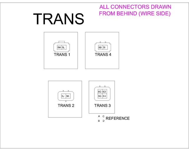
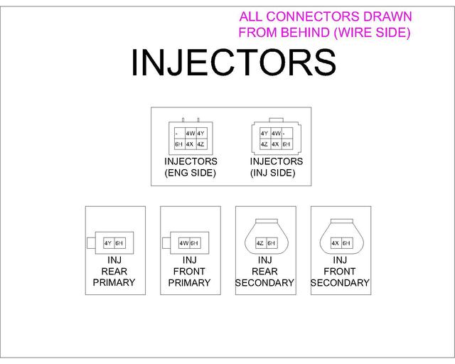
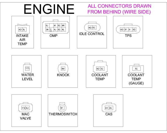
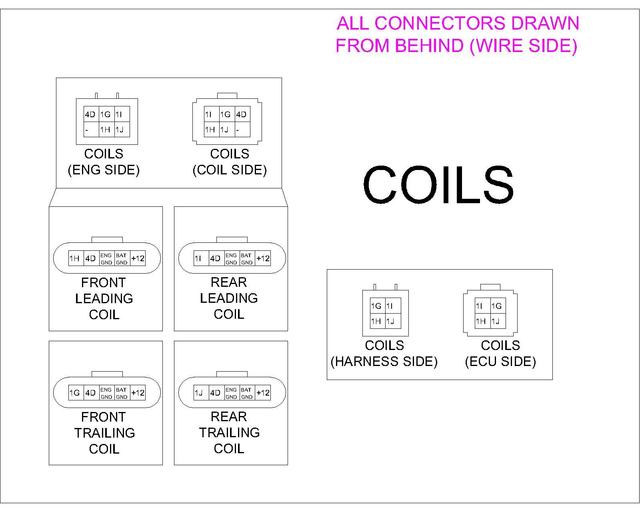
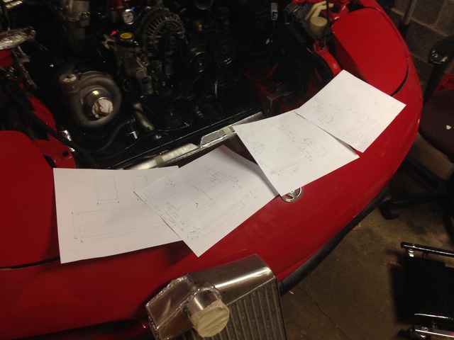
Once the motor was in It came time to wire a new engine harness. I needed a custom harness to fit exactly how I had my engine harness set up. I wanted my coils triggers to run though the harness to make sure all wiring was organized and I wasn't pulling pins from other connectors in the engine bay as the Sakebomb kit does. I also new anything off the shelf wasn't going to fit as I wanted it to and I was not paying $650 plus for something trivial(but time consuming). About $200 in parts and a few hours mapping and I was ready to begin wiring. I have these charts in PDF format if anybody would like to do the same.
Disclaimer about my charts that I am going to provide here. Some things may be wrong and I have found and fixed mistakes since uploading these pictures to the host site.
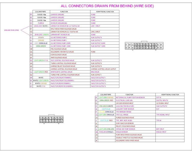
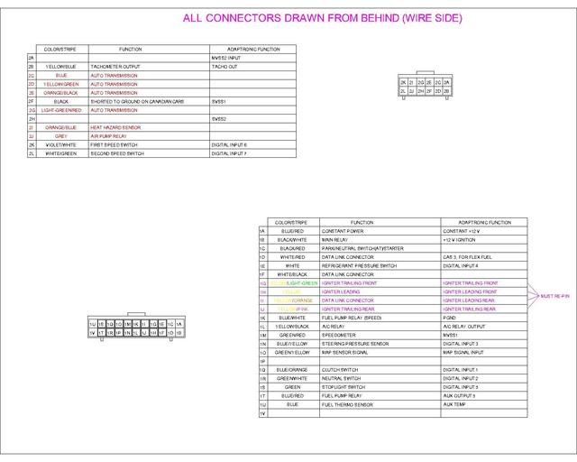
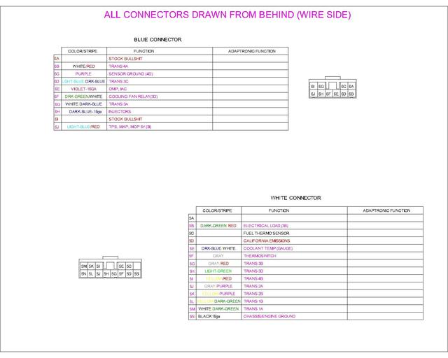
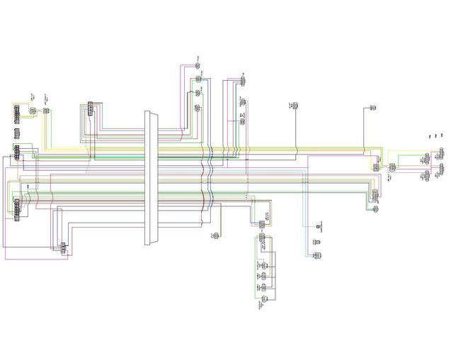
Disclaimer about my charts that I am going to provide here. Some things may be wrong and I have found and fixed mistakes since uploading these pictures to the host site.


With the motor in and the wiring diagrams complete I could start wiring the engine harness. A good crimping tool and a lot of patience is essential for this job. There is a lot of test fit, remove, test fit again, repeat over and over. I started with a bundle of wires from DIYautotune which is intended for use with a Megasquirt but was the best quality wire I could find and it's a cost effective $45 for the 10' bundle. I crimped the in car connectors on and measured for length on my stock harness and this is where I began.
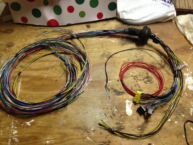
Dropped the loom in the car and began the long tedious process.
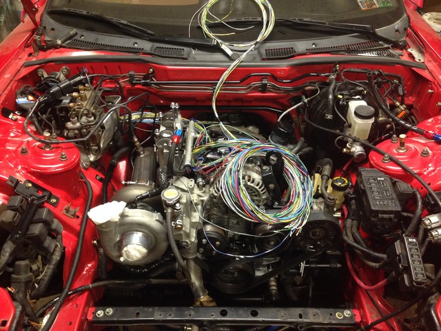
Many hours and test fits later and I was nearly done.
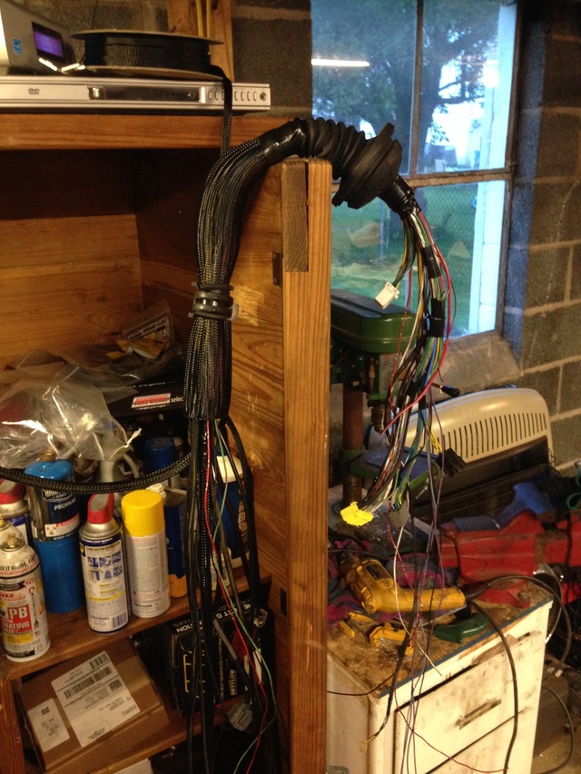
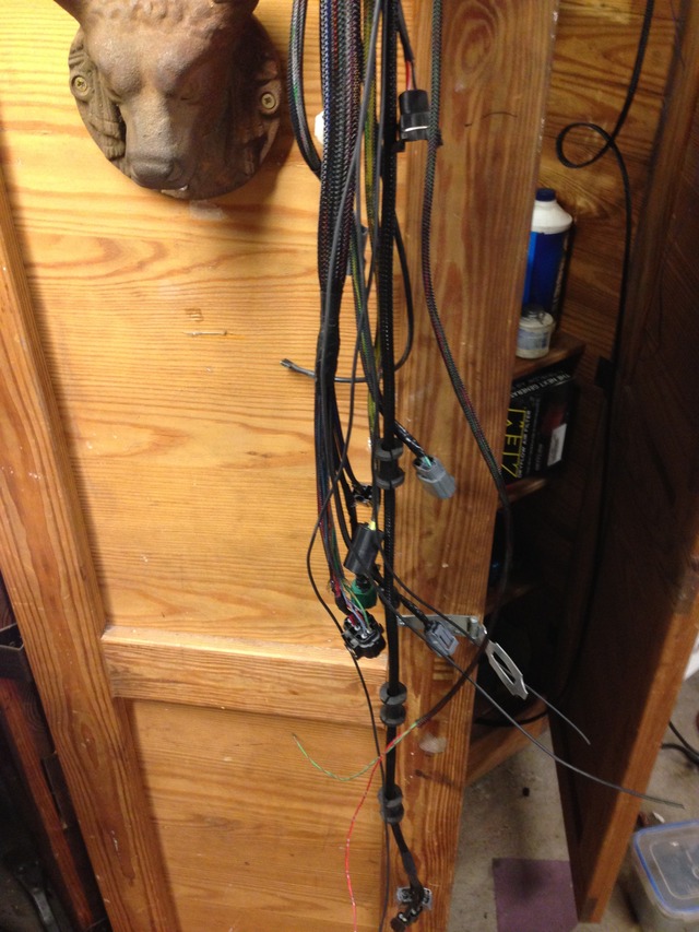
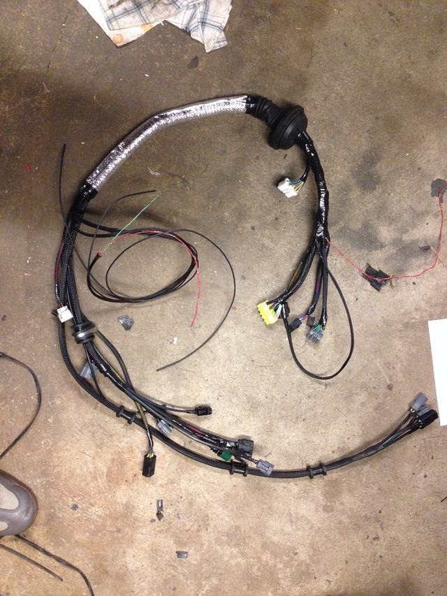
And here's the final product(minus finished grounds). I designed the harness so the coils and injectors had sub harnesses so I can remove the harness more easily if I have to take it out of the car or I swap injectors in the future. In hindsight I should've made a sub harness for the transmission but I can get a connector for that and do it in the future. It really is a shame that something so time consuming and beautiful is essentially hidden once its installed.

Dropped the loom in the car and began the long tedious process.

Many hours and test fits later and I was nearly done.


And here's the final product(minus finished grounds). I designed the harness so the coils and injectors had sub harnesses so I can remove the harness more easily if I have to take it out of the car or I swap injectors in the future. In hindsight I should've made a sub harness for the transmission but I can get a connector for that and do it in the future. It really is a shame that something so time consuming and beautiful is essentially hidden once its installed.


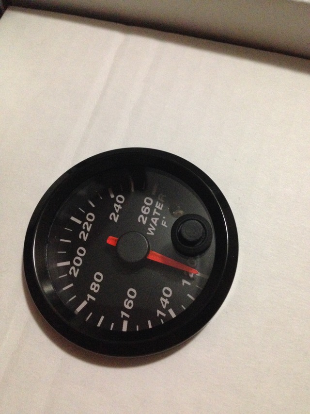
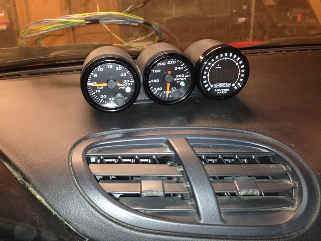
While I was making the engine harness I kept taking breaks and jumping over to another project that somewhat had to be done at the same time. This was wiring my gauges. It also took some of the monotony out of wiring the engine harness. I went with Speed Hut water temp and boost gauges and an innovate MTX-L wideband.
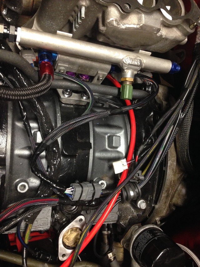
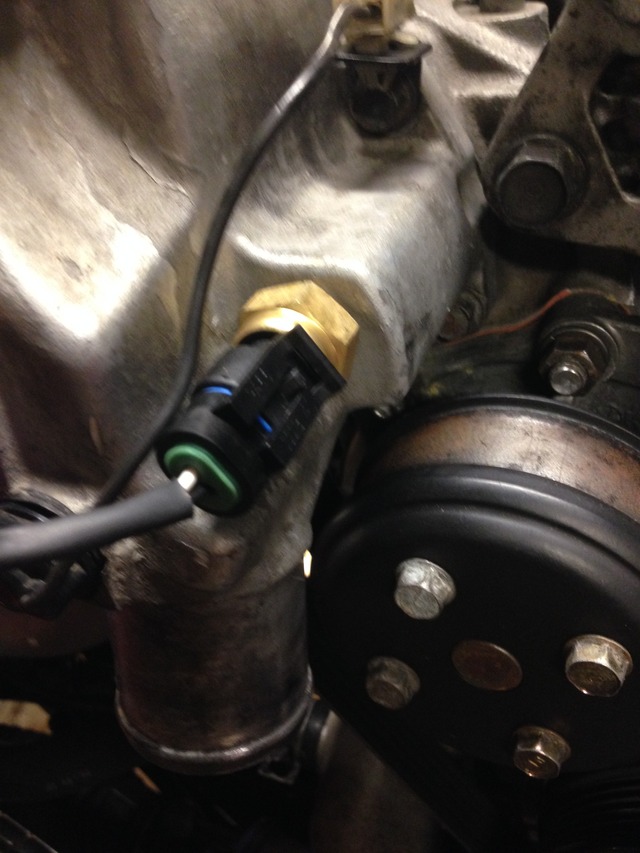
Water temp sensor mounted in the thermostat housing
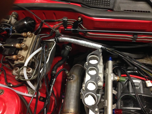
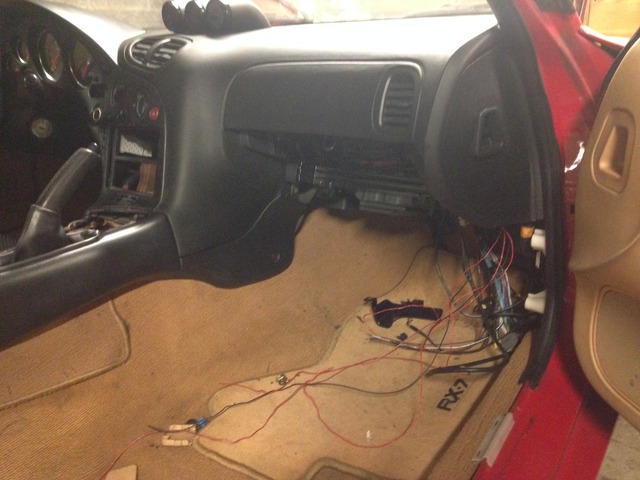
Wiring always has to look terrible before it gets done
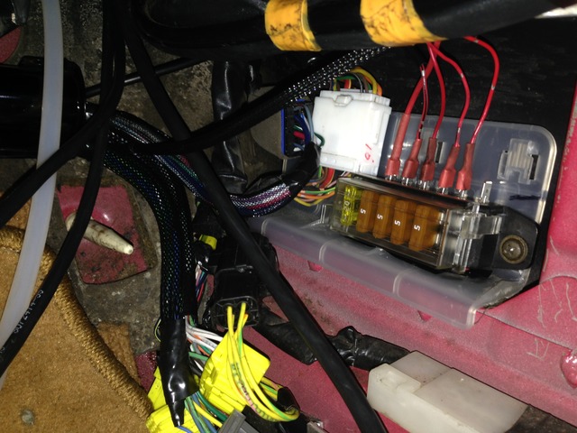
Fuse block all wired up. This will power my three gauges and my MAC solenoid valve. Only downfall is the location of this panel. It's behind the ECU so if I ever do pop a fuse Ill have to unbolt the ECU to change it.
Gauges all mounted up. I'm not sure if this was taken before or after they were wired but the mounting is obviously the same.

Water temp sensor mounted in the thermostat housing

Wiring always has to look terrible before it gets done

Fuse block all wired up. This will power my three gauges and my MAC solenoid valve. Only downfall is the location of this panel. It's behind the ECU so if I ever do pop a fuse Ill have to unbolt the ECU to change it.

Gauges all mounted up. I'm not sure if this was taken before or after they were wired but the mounting is obviously the same.

Just be meticulous about it. Crimping takes patience so take your time and double check each crimp to make sure its tight. Buy extra terminals for your connectors, because you will mess some crimps up or want to change routing while your at it. The last thing I would recommend is to make as many solder connections as you can inside the car. You'll have to splice a few wires together such as sensor grounds so to eliminate the chance of weather affecting them I just ran a separate wire from each connector and spliced after the grommet.
Long time no update. Progress has been slow on finishing the car but that seems to be the case with all projects. The wiring was finished a while ago but I could;t attempt to fire the car because I had no radiator at the time. I had a plan in the works but everything takes much longer than expected.
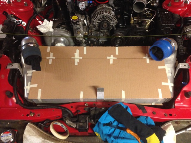
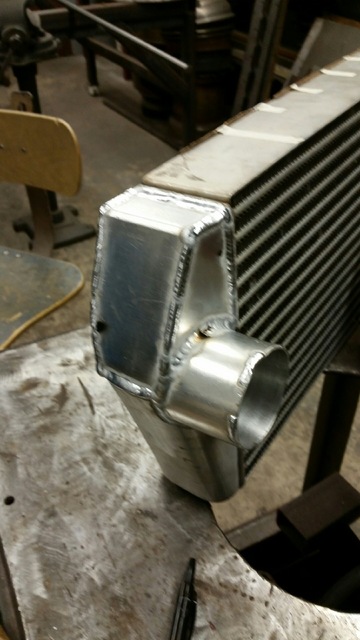
I knew I wanted a VMIC but didn't want to ditch my Greddy FMIC core because I really wouldn't get enough for it to cover the cost of a suitable IC core. So I set my friend on the task to modify the core for VMIC use. We mocked things up a little on the car first to see what needed to be done and then set off on modding the core. I also bought a new Koyo rad to modify for VMIC use.
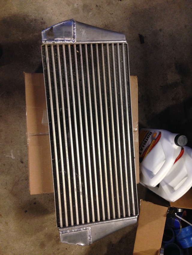
I knew I wanted a VMIC but didn't want to ditch my Greddy FMIC core because I really wouldn't get enough for it to cover the cost of a suitable IC core. So I set my friend on the task to modify the core for VMIC use. We mocked things up a little on the car first to see what needed to be done and then set off on modding the core. I also bought a new Koyo rad to modify for VMIC use.


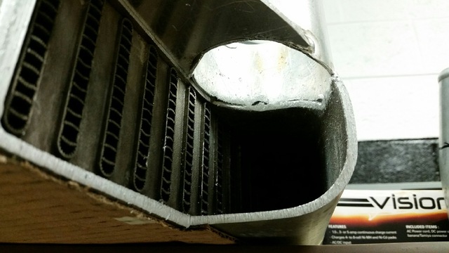
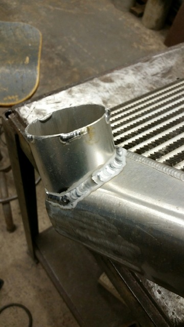
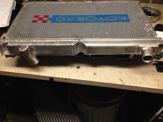
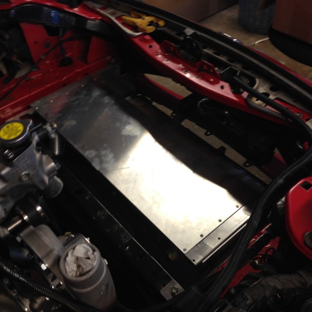
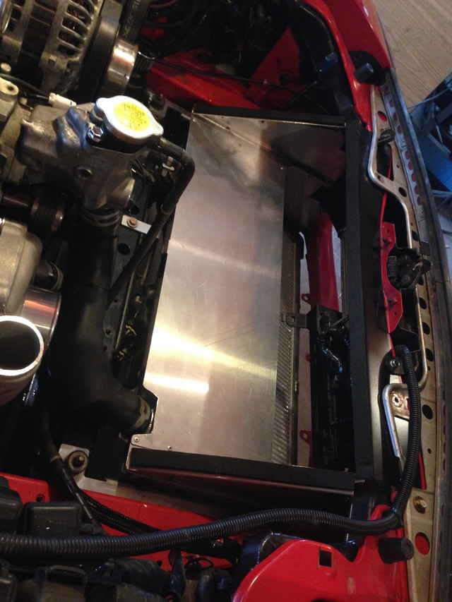
Finished modified Koyo for the VMIC. Welded a new upper end tank in, divider between the two, and closed off the bottom rad outlet. I took a whole lot of measurements and made some rough sketches of the mounting brackets and ducting, leaving plenty of extra to be able to trim the panels to fit as needed. From these trimmed panels I may make panels exactly to size for a slightly cleaner look.
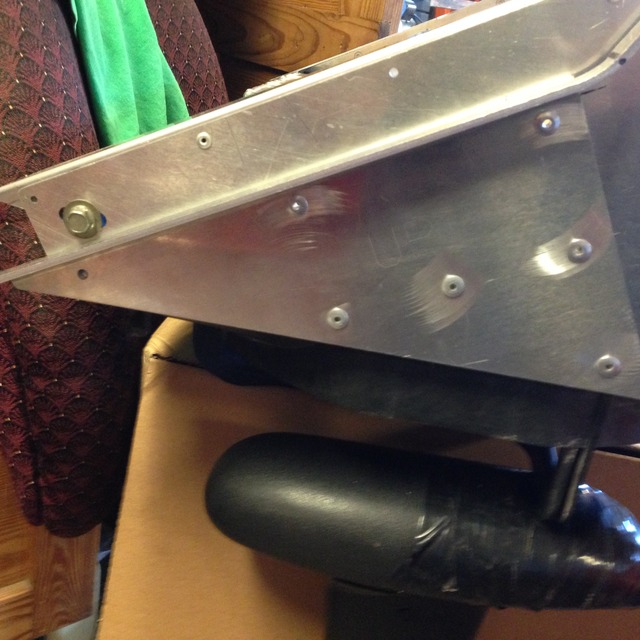
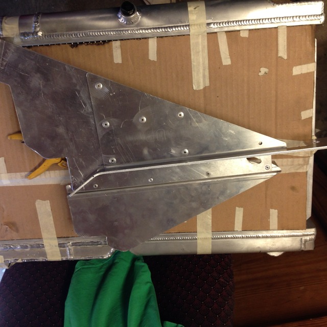
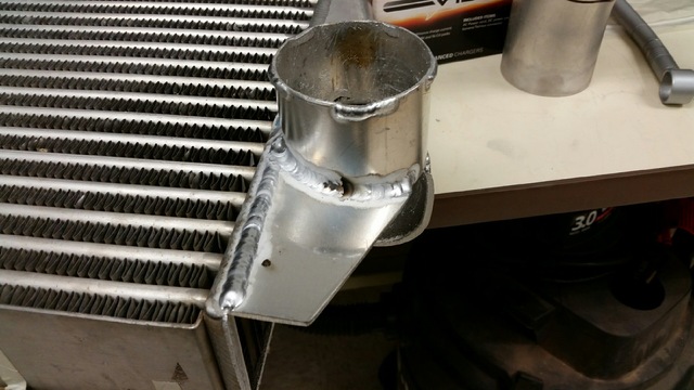
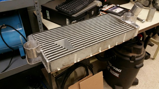
Finished ducting


Finished ducting


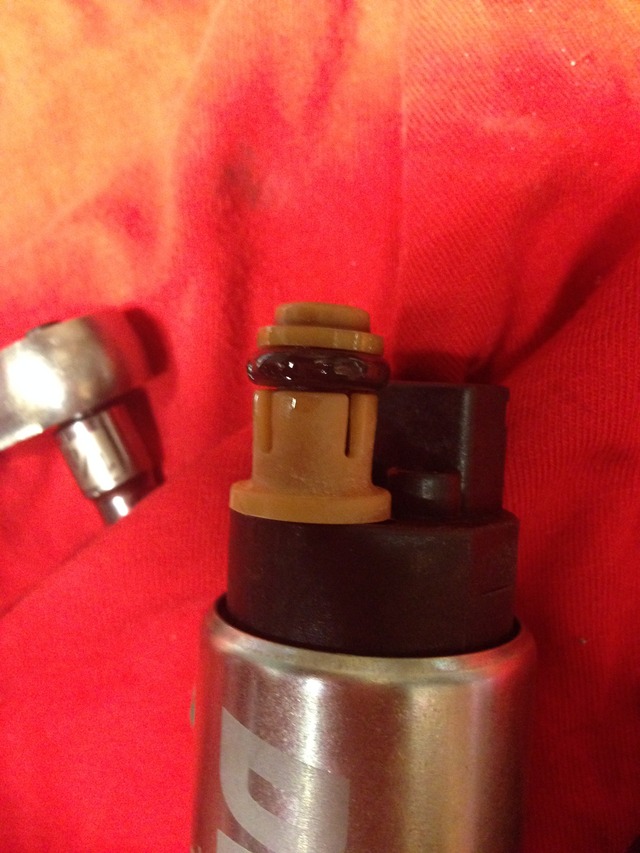
I'm going to go back to the fuel pump install for a post here because the way I did it could be pretty useful to others on here. The DW-300 isn't exactly a direct fit but this is to be expected. Luckily it is setup to be a direct fit in a lot of other cars, a miata being one of them. This makes it pretty easy to use the stock hanger, fuel line, and o-ring/seal. The fuel feed tube was set up just like the OEM pump, just a hair shorter. I took the plastic collet piece and sanded a few thousandth off the bottom side to allow it to fully seat on the pump outlet. Then it was just a matter of popping the pump into the hanger feed and fastening it to the hanger.
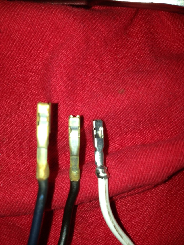
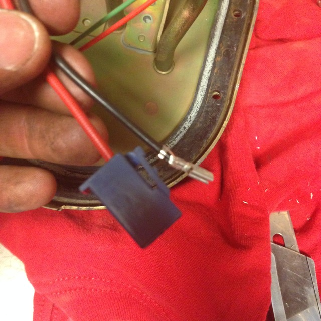
As for the wiring, I wasn't ok with cutting and splicing, especially in the tank with those tiny stock wires. I thought about adding my own bulkhead connector but thought that could create other issues that I don't need. Easy and lucky solution. The crimp on pins for the IAC connector happen to be almost an exact match, with only the crimp portion being different. This meant simply de-pin stock connector and crimp new pins onto the DW300. No cutting, soldering, or crimping old wires together.
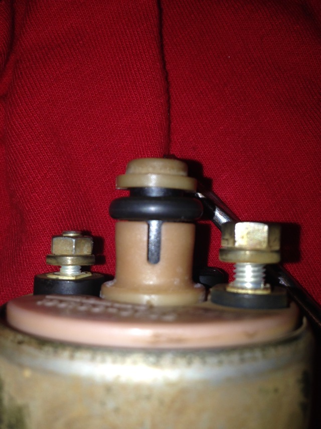
Stock pump feed
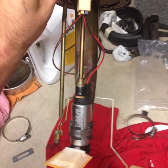
DW-300 with stock feed attached after some slight modification
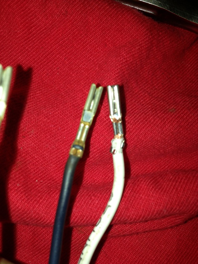
New pins Vs old pins (don't worry about the bad crimp, that was just me testing if these would work)
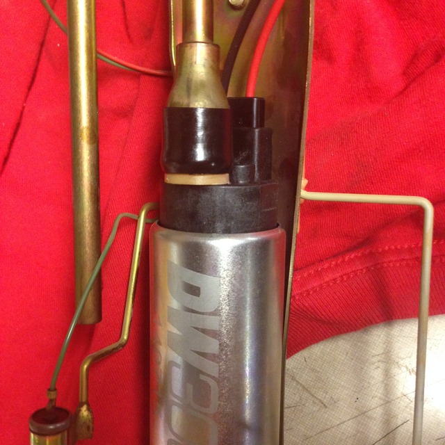
Finished assembly
As for the wiring, I wasn't ok with cutting and splicing, especially in the tank with those tiny stock wires. I thought about adding my own bulkhead connector but thought that could create other issues that I don't need. Easy and lucky solution. The crimp on pins for the IAC connector happen to be almost an exact match, with only the crimp portion being different. This meant simply de-pin stock connector and crimp new pins onto the DW300. No cutting, soldering, or crimping old wires together.
Stock pump feed

DW-300 with stock feed attached after some slight modification


New pins Vs old pins (don't worry about the bad crimp, that was just me testing if these would work)


Finished assembly

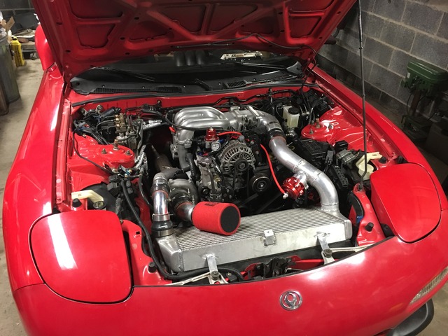
Update on the car. VMICis complete and the car is running. It's currently running on a map I picked up from the Adaptronic forum that had specs similar to my setup and it's acceptable for the time being. Working on getting the car to IRP for a check-up and some base tuning so I can get some good break in miles on it. VMIC is working flawlessly. Had the car out today on a 75 degree PA spring day and temps stayed at a solid 180-185. Only issue Left to sort out is an illusive exhaust leak but I think new midpipe gaskets will solve the issue.
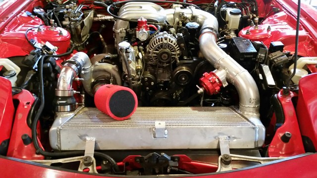
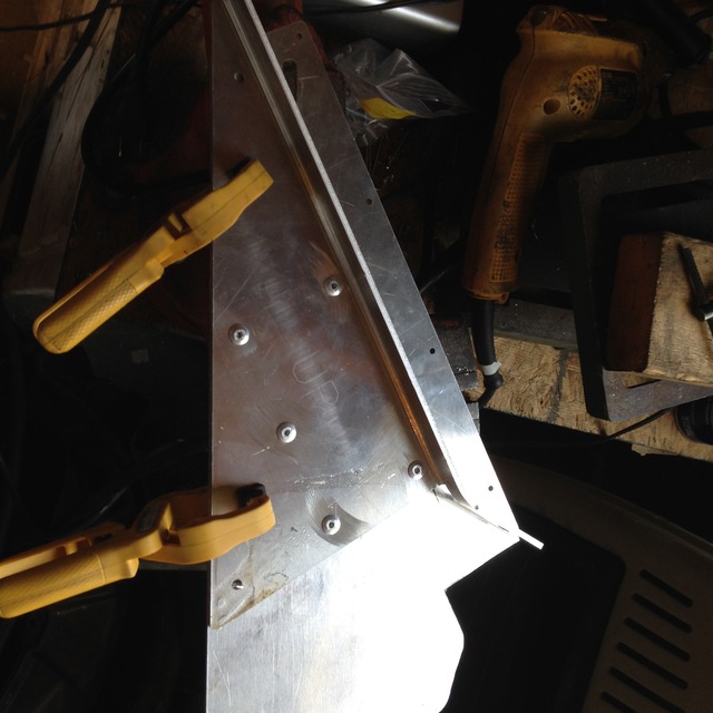
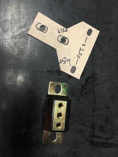
I had to remount the ignition coils for ease of access. The AC bracket location was nearly impossible to access so I remounted them in the cruise control location. Being an engineer I couldn't justify purchasing the Sakebomb kit. A few measurements, some cardboard mockups, CAD files, laser cut parts and a little bit of time, Coil Bracket.
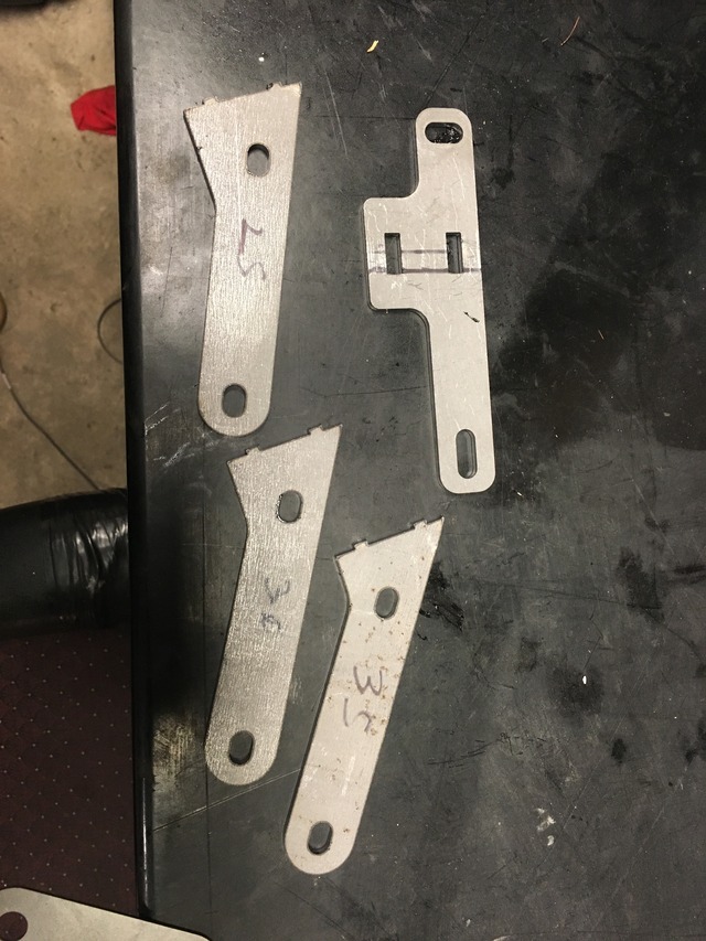
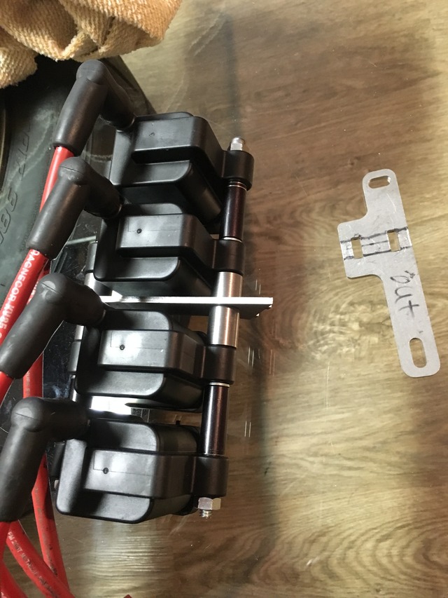
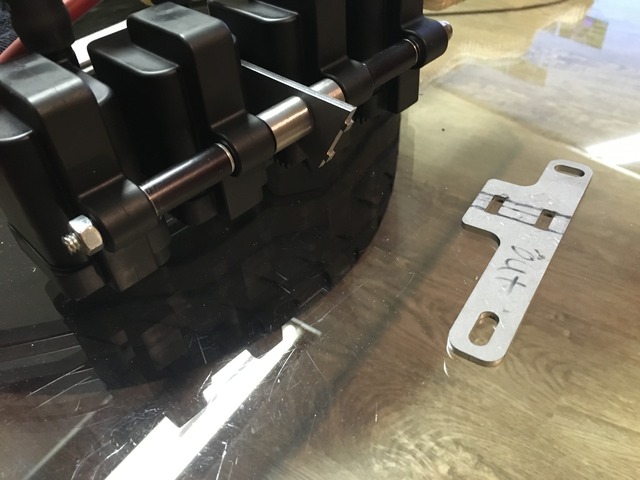
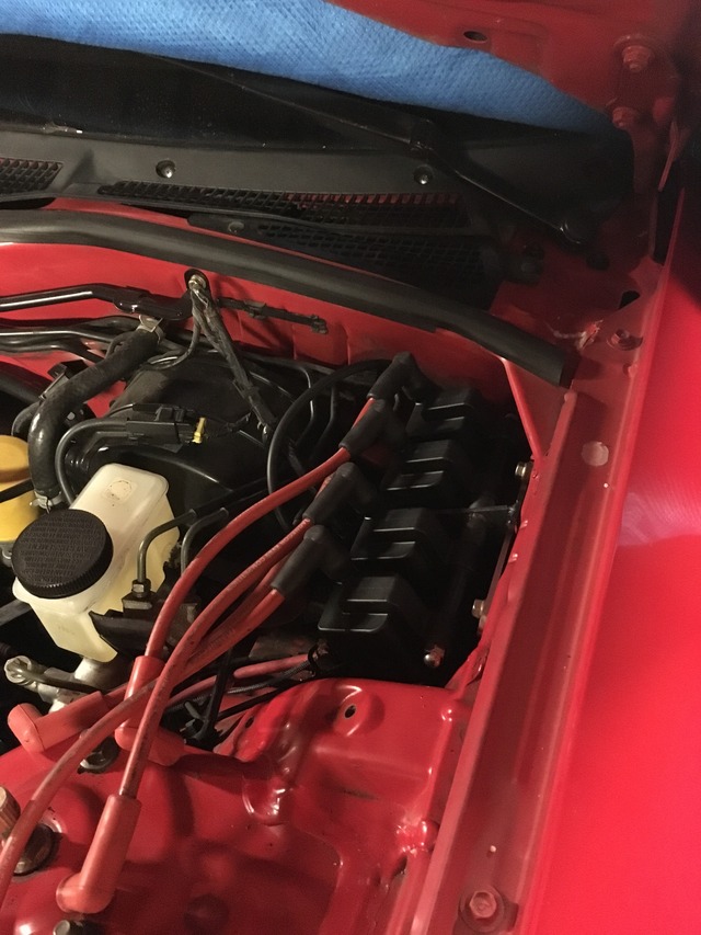
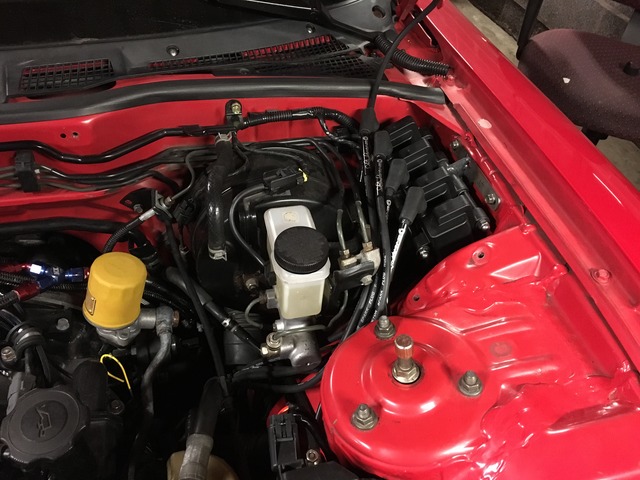


I had to remount the ignition coils for ease of access. The AC bracket location was nearly impossible to access so I remounted them in the cruise control location. Being an engineer I couldn't justify purchasing the Sakebomb kit. A few measurements, some cardboard mockups, CAD files, laser cut parts and a little bit of time, Coil Bracket.


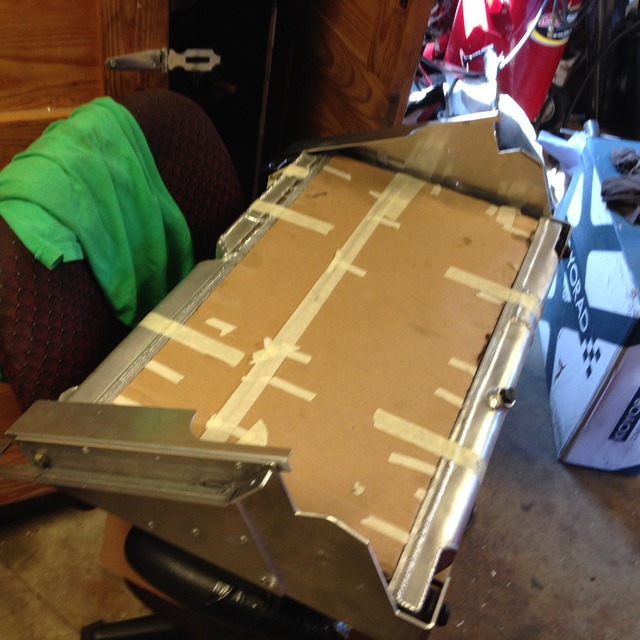
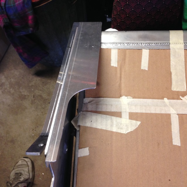
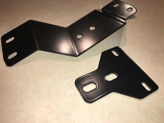
With the weather being on and off here and my tune being a little sketchy I haven't driven the car much. In the downtime I took it upon myself to make a transmission crossmember. I couldn't justify buying the Banzai crossmember because of my skill set and access to equipment. After looking over some bushing, designated transmission mounts, and space constraints I decided that the Banzai method with a Camaro trans mount from energy suspension would be the best option. There is a reason Banzai went with this mount, it's compact, inexpensive, and specifically designed for this application. Did some cardboard templating, measuring, more measuring and a light gage mock up. Welded and powdercoated product soon to come!
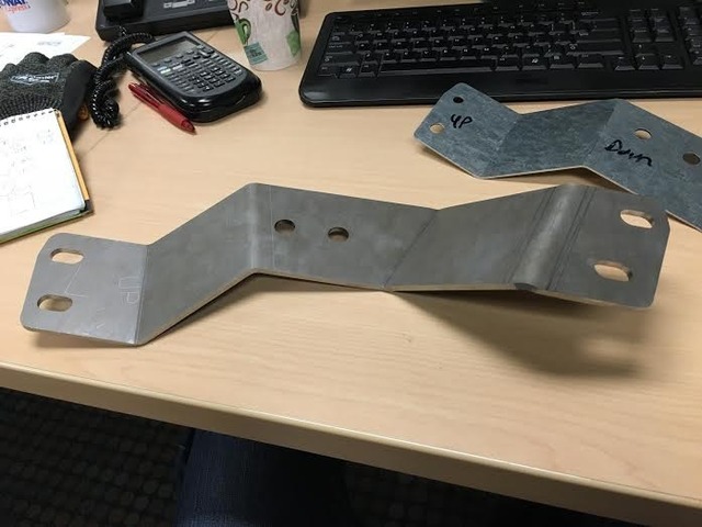
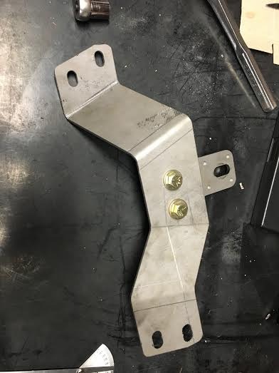
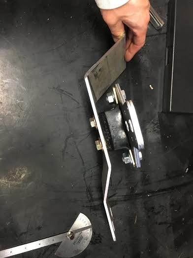
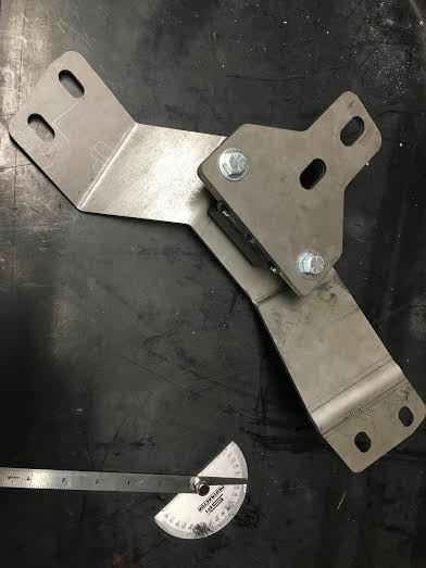
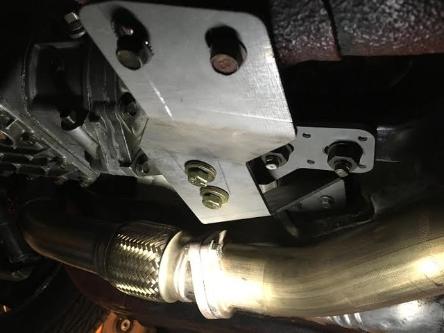
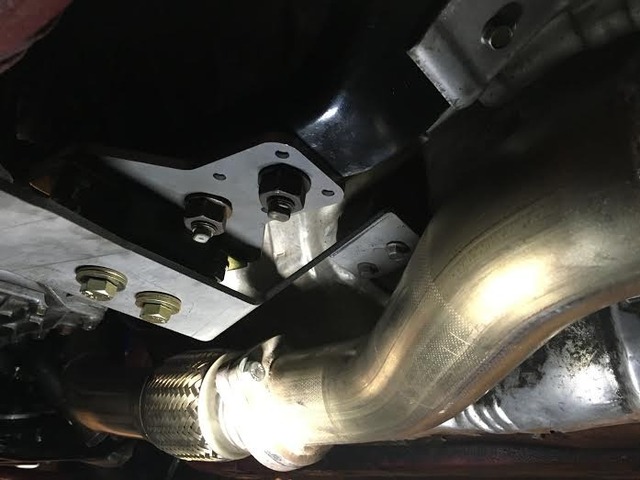


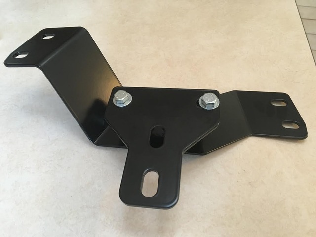
Finished transmission crossmember. Will install in the next few days. I've been daily driving the car without issue due to Subaru problems. If people are interested in these I can deliver them for an incredible price if I produce a quantity of 10 or greater. Made out of 8 gauge (0.160" thick) carbon steel, laser cut and press brake formed.


Last edited by Turk82; May 19, 2016 at 11:47 AM.

Thread
Thread Starter
Forum
Replies
Last Post