The Monsterbox 4 Rotor
#1853
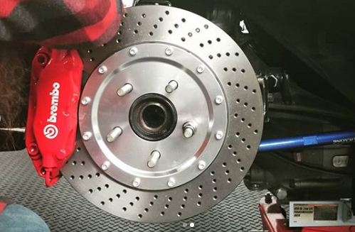
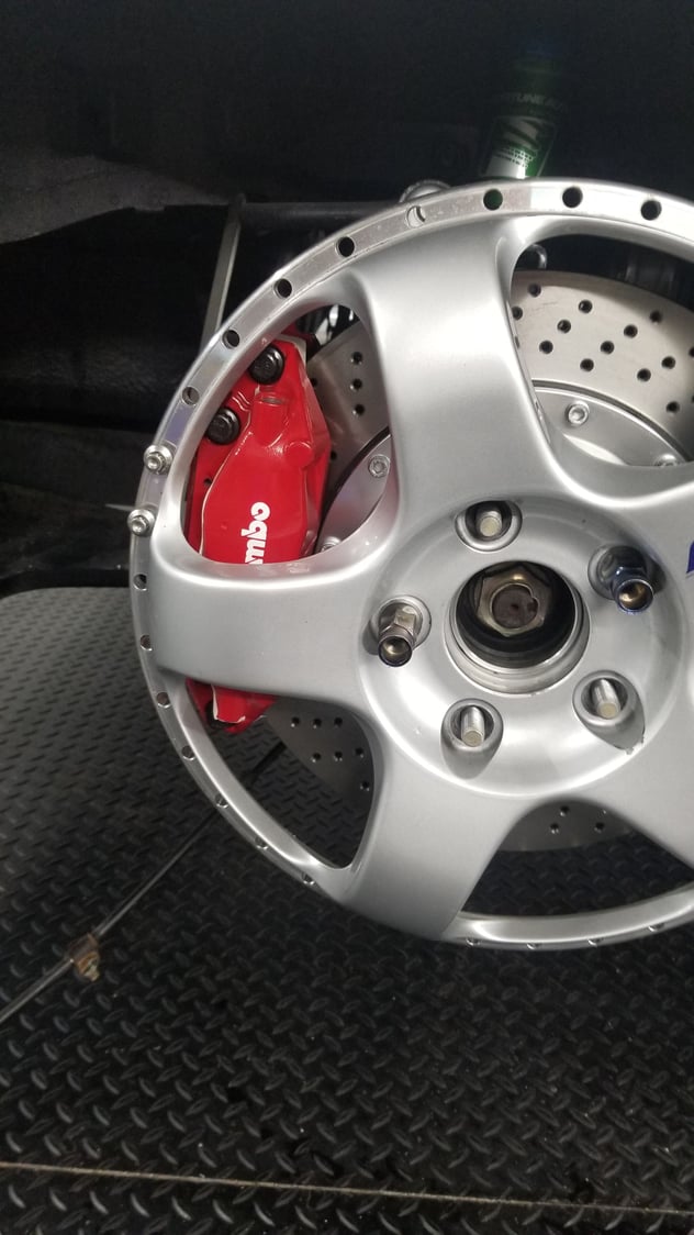
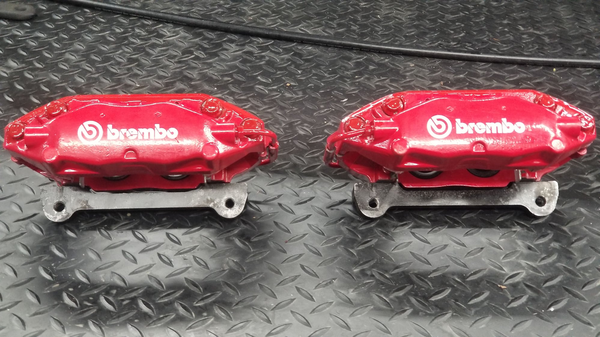
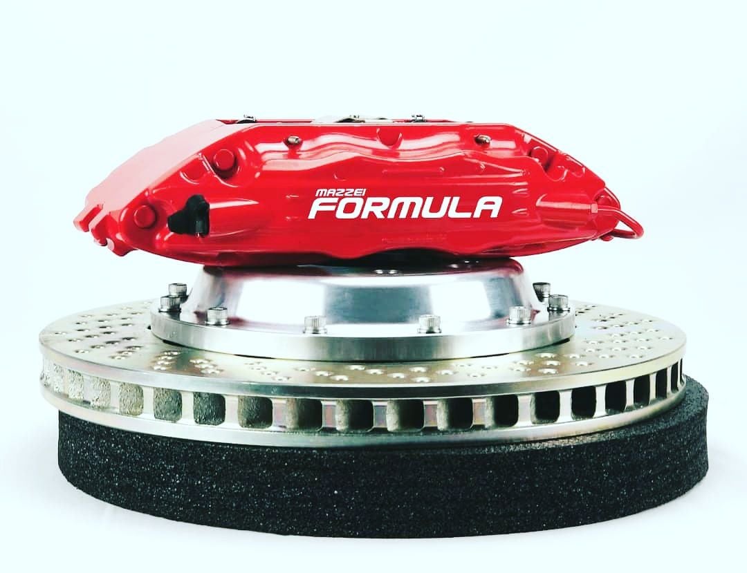
got it pretty close. Was off by about 1.75mm on caliper shimming. Just need to grind the bracket down 1.7mm on a mill.
Wheels don't fit too well, being that they are step lips. Takes about 10mm of spacer and grinding to make it work. I have no issues grinding the f*** out of these calipers to make the step lips fit. Update when finished grinding and fitting.
#1854
I saw the insta post with the rear wheel/tire mounted up with the spacer.
An alternative to running a narrower tire and stretch would be-
widen the existing wheel by adding to the inner barrel (usual way) for more offset and run the same or even wider tire size depending on how wide you go.
Offset places the tire, so adding more inner width will recenter the tire inward away from the fender.
With the big **** downforce and high speeds even a quick rub of the tire on some fiberglass fender over a bump could lead to a highspeed blow-out.
#1855
The Ancient
You need different offset wheels, Zach.
#1856
yokohama tire is 284mm sidewall on 280 size tire with a section width of 292mm
the Pirelli is 276mm sidewall in the 280 size with section width of 285mm
therefore its possible the Pirelli would do the job without having to change the wheel offsets, I was entertaining this idea before selling the wheels and/or purchasing barrels and lips to rebuild the rear.
If I rebuild the rear, i'd likely try to go 13inches and fit the 338mm 27.8inch slicks
#1857
Decked the rear brackets 1.5mm, now the caliper/rotor clearences are dead even on each side of the rotor
Took 2mm off the outside face of the caliper, so now the calipers clear the wheels with only 10mm of spacer required,
the plan now is to rebuild the wheels with 12.5mm (1/2") shorter lips, and 1/2inch wider barrels. This will move the offset inwards, to counteract the 10mm spacer while giving an additional 2 to 2.5mm of clearence. May take this opportunity to widen the wheels an extra inch, derived by adding an additional inch to the inside barrel (+1inch added to the +0.5). This will allow for a 300+mm tread width tire, which will maintain the same profile/aggression of the current 280mm on the 11inch wheel, while still being +/- 2mm to the original flushed fitment before spacing the wheels for the brakes.
The original barrels from the rear wheels will then be used on the front wheels, which will add another half inch to the front wheels, making them 10inches. This will allow a nice 250-260mm upfront, an increase from the current 240mm tires.
Game plan is looking good.
bashed the ever living **** out of the trans tunnel and finally having the transmission clearing nicely. Now onto figuring out the pnuematics while waiting on the input shaft and adapter kit
#1859
yea that looks pretty cool,
it takesa bit of stuff to make a paddle setup work properly. The safest and most efficient way is with a gear control unit that interfaces with paddles, actuator, and ECU. There's a race car driver local to me, who's selling an entire air setup off of a Corvette serious race program, which has everything needed to make the system functional, for pretty cheap. At this point its sort of a risk management, time management, and cost reasons that I'll likely go with the air.l
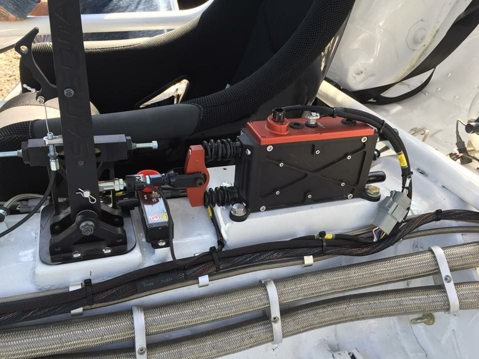
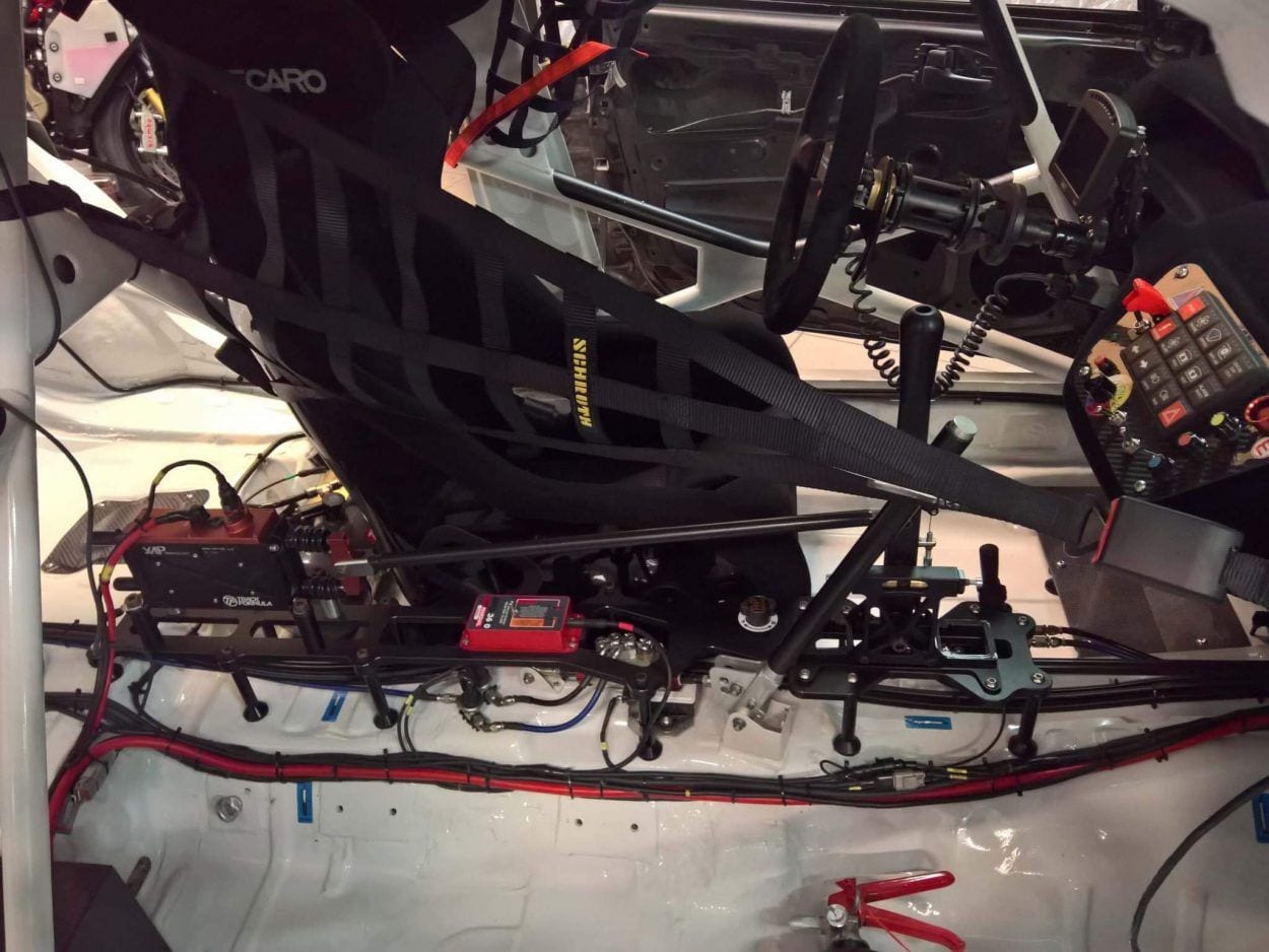
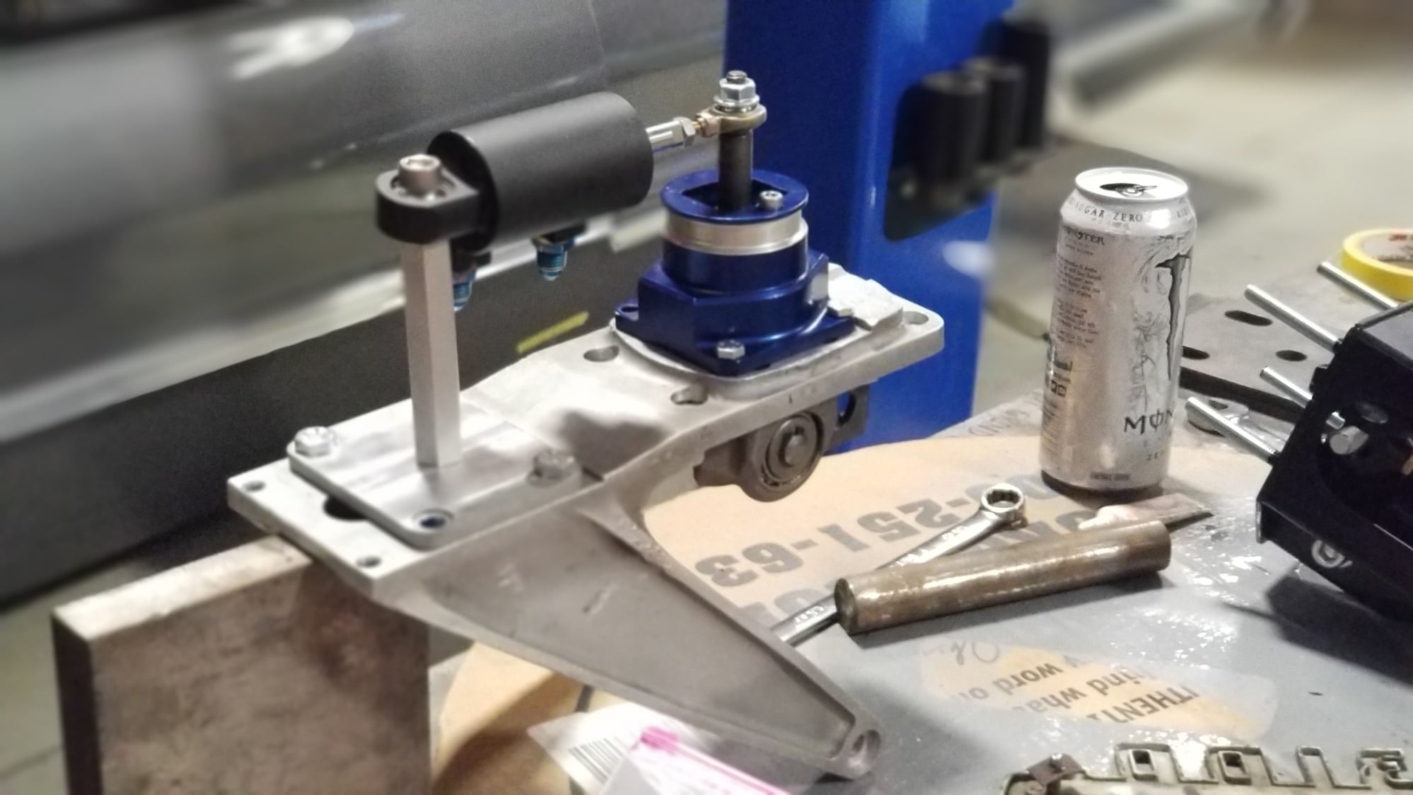
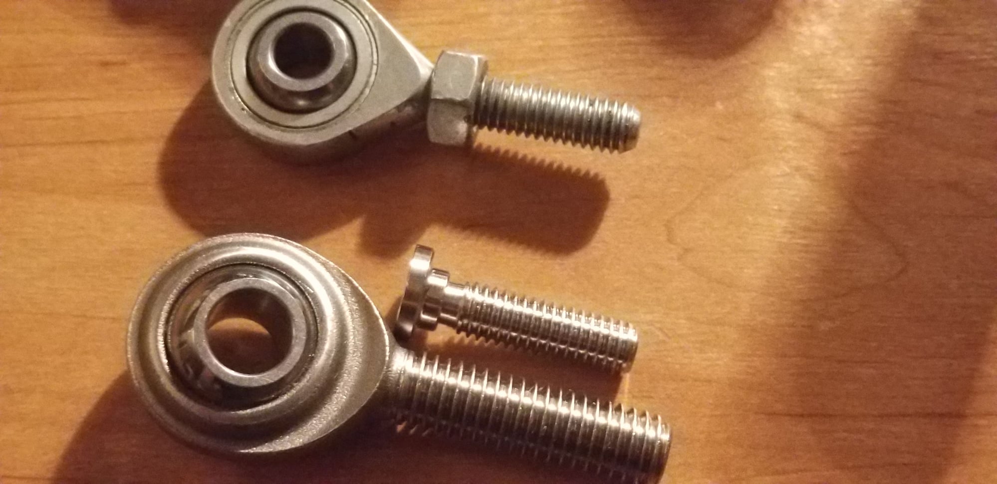
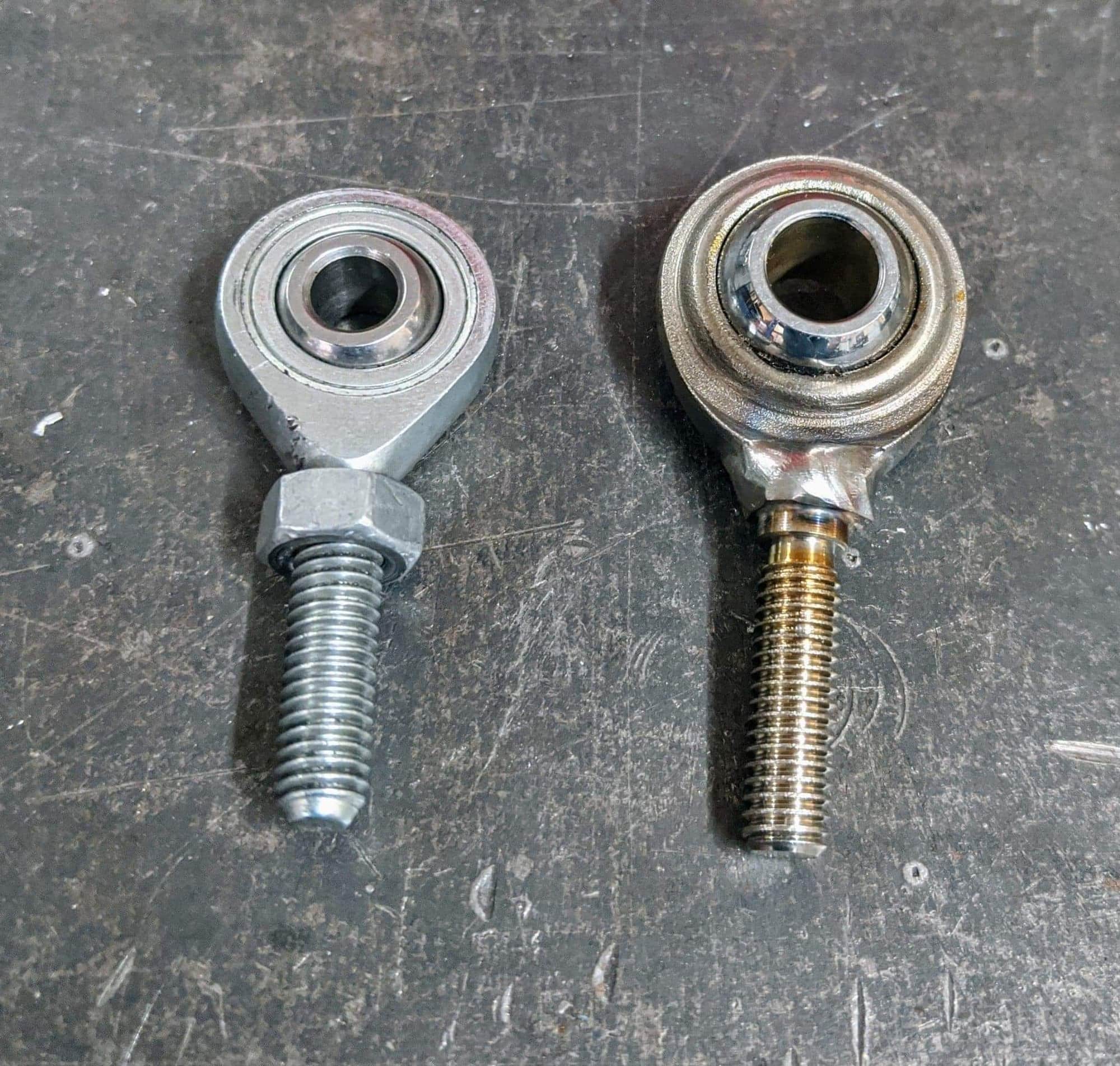
I'm setting it up so that hte shifter can be removed and replaced with actuator. So that they are interchangable. Basically you'll be able to pin the shifter in place, and the actuator will replace the linkage/heim-joints that run from the shift lever to the shifter mechanism on the box. When you wish to go back to manual actuation, simply remove the air actuator, and replace it with the solid linkage/joints and unpin the shifter so you can move it forward / backwards again
#1860
it takesa bit of stuff to make a paddle setup work properly. The safest and most efficient way is with a gear control unit that interfaces with paddles, actuator, and ECU. There's a race car driver local to me, who's selling an entire air setup off of a Corvette serious race program, which has everything needed to make the system functional, for pretty cheap. At this point its sort of a risk management, time management, and cost reasons that I'll likely go with the air.l
I'm setting it up so that hte shifter can be removed and replaced with actuator. So that they are interchangable. Basically you'll be able to pin the shifter in place, and the actuator will replace the linkage/heim-joints that run from the shift lever to the shifter mechanism on the box. When you wish to go back to manual actuation, simply remove the air actuator, and replace it with the solid linkage/joints and unpin the shifter so you can move it forward / backwards again
I'm setting it up so that hte shifter can be removed and replaced with actuator. So that they are interchangable. Basically you'll be able to pin the shifter in place, and the actuator will replace the linkage/heim-joints that run from the shift lever to the shifter mechanism on the box. When you wish to go back to manual actuation, simply remove the air actuator, and replace it with the solid linkage/joints and unpin the shifter so you can move it forward / backwards again
*edit* I kind of liken it to the PDM of paddle shifting, its ultimately simpler, easier to implement, but it's taking longer than one would expect for it to become a standard since people are reluctant to adopt new things once they've decided on a team. Or maybe I'm wrong. Iunno.
Last edited by dguy; 12-30-19 at 11:34 AM.
The following users liked this post:
Darkning (01-06-20)
#1864
Looks like the gearset was only 1 chipped tooth on 3rd gear. And it could have occured by a missed shift. Sometimes when you shift with the clutch, the dogs don't fully disengage because there is no pre-load force on the slider, and every once in a while on rare occasion from 2nd gear to 3rd gear, the 2nd gear slider will stick but the shifter will go onward and get stuck in neutral position while the gear is engaged in 2nd. The driver can't get out of 2nd gear and can't engage 3rd. In this situation you have to drop the oil pan and pop the selector back to neutral so that the shifter and sliders are in synch. In the video it looks like the driver used the clutch from 2nd to 3rd and 2nd gear bounced back and stuck in gear, while he tried to jam it into 3rd. This tries to force the transmission to select 2nd and 3rd at the same time, which I'm 90% sure broke the 3rd gear. The broken tooth then seperates the shafts/bearings and cracks the case. With a new 3rd gear it should be good to go, keeping in mind that fast shifts must require clutchless and preloaded actuation
It does not appear to be the power that broke the transmission. According to the video, 3rd gear was never engaged on the racetrack, yet 3rd gear was the one that broke...
It does not appear to be the power that broke the transmission. According to the video, 3rd gear was never engaged on the racetrack, yet 3rd gear was the one that broke...
#1868

Trimmed the Dash for the Sequential

Rebuilt the front wheels, just waiting on the barrels for the rear. Powder coated Porsche silver metallic.

Input shaft and parts arrived

Mint

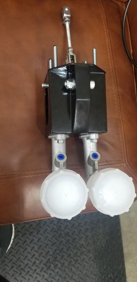
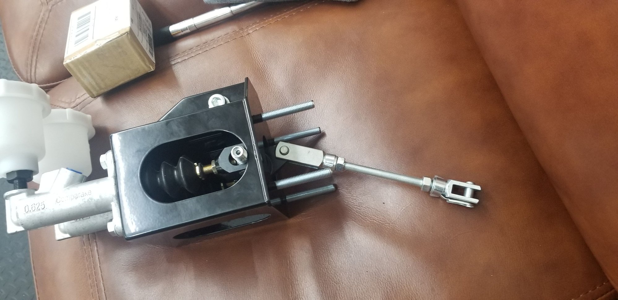
Manual Lever + Pneumatic Actuation

Tilton Remote balance bar adjustment

Toyo Racing Slicks Brand New

Geartronics system installed with Carbon Paddles, Neutral Interlock Switch Green and Momentary Line Lock Blue

Valves

Compressor

Blip Actuator
Swapping input shaft tomorrow. Looking forward to half mile, quarter mile, and road atlanta. Planning to turn it up from 1100hp to 1300hp so we can do boost by gear and ramp it up on the top end for the new transmission
#1870
Will explain it in sequence of upshift / downshift,
So for an upshift,
1. Driver selects the Upshift Paddle
2. Upshift paddle grounds the Upshift Input on the Gear Control Unit (GCU)
3. GCU Throws a Generic 5V signal output to the Haltech ECU, to signal Torque Interruption/Reduction
4. ECU cuts spark by a specific percentage of engine cycles (90% cut, 80% cut, etc)
5. While the Torque Reduction is Active, the GCU simultaneously grounds the Upshift Solenoid, which fires a 150PSI air charge to the "pull-back" side of the actuator on the transmission gear selector
6. During the Torque Reduction sequence/firing sequence, the GCU is also WATCHING, the gear position sensor. The gear position sensor is a hall-effect sensor located on the sequential selection barrel. Each gear position has a voltage "window". Initial movement of the barrel/sensor, indicates the "upshift" is in-progress, and the gear selection is "complete" once the voltage is now within the tolerance window at the end of the movement.
7. The duration of the Torque Reduction signal, sent to the ECU, is directly tied to the initial/complete voltages of the gear position sensor. They call this "closed-loop" torque reduction/shifting. So basically, torque is only reduced as long as necessary for the gear change to occur, yet it is never reintroduced Too Early, like in the middle of a gear change. This is what happens with older tech Strain Gauges that use open-loop timer settings in ECU. Some shifts occur faster than others, and we used to rely on a timer, say 150-200ms, to cut spark. Driver might have already made the shift, before the spark is re-engaged, and there's a slight wait period of a 50-100ms before power comes back on. Its too risky to lower the timer, because if the driver doesn't pull the shifter hard enough or fast enough or something goes wrong with the gear change, the power might be re-engaged before the gear change is in the safe window of completion, and you'll round of the dogs or beak the box. Closed loop prevent this from happening, while always maintain the fastest possible shift time. Fastest shift time is now all determined by air pressure and solenoid performance
8. another trick i'll be playing with is blending the torque back in. When the GCU de-activates the spark cut signal to the ECU, the ECU would normally immediately resume full power. But we can play with this, by adding a gradual recovery of spark cut % back to 0% cut over 200ms or so. And we could play with a retarded timing ramp out. So any time the cut occurs, power is always brought back on with a pre-set -30* retard, which is ramped out to baseline timing over a desired millisecond time frame. This will essentially calm down the upshift aggression, so that although the shift will be abrupt, and power comes back on-line, there will be less "shock" to the drivetrain as the ramp out duration and amount should dampen the drivetrain.
For a Downshift, its a little more complicated,
1. Driver pulls the downshift paddle
2. signal to GCU, GCU responds a little differently this time
3. GCU actually cuts spark on downshift, using the same method, sending signal to the ECU for "active" torque reduction
4. ECU cuts spark
5. At the same time the spark is shut off, the GCU sends two signals, one to the Blip Solenoid and One to the Downshift Solenoid, however these signals can be adjusted in timing from one another, both start time, and duration
6. In a nutshell, the throttle will be blipped with an air-charge to the throttle body, while (essentially) simultaneously shifting the transmission selector down 1 gear
7. While this is all happening, the spark will be turned back on in the process, but only while the gear selection is within a certain voltage range/position within the rotation
8. The goal here is to cut the spark before the throttle blip, so that the throttle is opened before spark is turned back on, making for the quickest blip time which also causes the least amount of "push". This is called "anti-push" strategy. This is so that you can downshift while ON THE THROTTLE and/or without ever using the clutch. There's a lot of strategy to play with here.
9. I haven't played with it yet, but for spark re-introduction I have some tricks to help the ECU know that its a downshift, and not an upshift. We do not want a ramp out on a downshift. So the ECU needs to know the difference between up/down. I believe I can do this by using a conditional TPS% threadhold for the ramp out. Meaning, if a certain TPS% isn't met, then ramp out won't occur. This way spark reintroduction is immediate upon de-activation of the spark cut signal UNLESS the TPS is over say 50% throttle, which indicates an upshift or major power trying to be transferred to the rear wheels. The logic here is that you're more than likely going to be under 50% throttle on a downshift. And if you're under 50% throttle on an up-shift, drivetrain shock won't be an issue anyhow. Therefore, you reserve the ramp-out for heavy throttle, which will always be upshifts. This may also have you wondering, well what about the throttle blip itself? Will that not trigger the ramp out, erroneously? It will not, because it should only need about 20% TPS for adequate blipping.
Aside from the shift strategies, you have the neutral lock-out/reverse lock-out. This is setup with a switch on the steering wheel to prevent shifting down into neutral on the racetrack by accident or reverse. You must hold the button while hitting the paddle for neutral. And you must hold the button for at least 2 seconds to get into reverse.
We also have air pressure adjustment, and pressure transducer on the accumulator tank. The pressure transducer gives the GCU ability to monitor accumulator pressure so that it can determine how and when to cycle the compressor.
That's about it lol
Last edited by Monsterbox; 03-02-20 at 03:40 PM.
The following users liked this post:
alexdimen (03-10-20)
#1871
Sick. Was watching F1 videos with the camera facing the driver/back of steering wheel.
The downshift controls seem like they'll take a lot of tinkering to get working right. Such fast downshifts and timed throttle blips.
Do you think it might be worth going to a drive by wire throttle and avoiding the blip solenoid?
The downshift controls seem like they'll take a lot of tinkering to get working right. Such fast downshifts and timed throttle blips.
Do you think it might be worth going to a drive by wire throttle and avoiding the blip solenoid?
#1872
Sick. Was watching F1 videos with the camera facing the driver/back of steering wheel.
The downshift controls seem like they'll take a lot of tinkering to get working right. Such fast downshifts and timed throttle blips.
Do you think it might be worth going to a drive by wire throttle and avoiding the blip solenoid?
The downshift controls seem like they'll take a lot of tinkering to get working right. Such fast downshifts and timed throttle blips.
Do you think it might be worth going to a drive by wire throttle and avoiding the blip solenoid?
#1875
sure, while it is still untested, this is my preliminary shift strategy
Will explain it in sequence of upshift / downshift,
So for an upshift,
1. Driver selects the Upshift Paddle
2. Upshift paddle grounds the Upshift Input on the Gear Control Unit (GCU)
3. GCU Throws a Generic 5V signal output to the Haltech ECU, to signal Torque Interruption/Reduction
4. ECU cuts spark by a specific percentage of engine cycles (90% cut, 80% cut, etc)
5. While the Torque Reduction is Active, the GCU simultaneously grounds the Upshift Solenoid, which fires a 150PSI air charge to the "pull-back" side of the actuator on the transmission gear selector
6. During the Torque Reduction sequence/firing sequence, the GCU is also WATCHING, the gear position sensor. The gear position sensor is a hall-effect sensor located on the sequential selection barrel. Each gear position has a voltage "window". Initial movement of the barrel/sensor, indicates the "upshift" is in-progress, and the gear selection is "complete" once the voltage is now within the tolerance window at the end of the movement.
7. The duration of the Torque Reduction signal, sent to the ECU, is directly tied to the initial/complete voltages of the gear position sensor. They call this "closed-loop" torque reduction/shifting. So basically, torque is only reduced as long as necessary for the gear change to occur, yet it is never reintroduced Too Early, like in the middle of a gear change. This is what happens with older tech Strain Gauges that use open-loop timer settings in ECU. Some shifts occur faster than others, and we used to rely on a timer, say 150-200ms, to cut spark. Driver might have already made the shift, before the spark is re-engaged, and there's a slight wait period of a 50-100ms before power comes back on. Its too risky to lower the timer, because if the driver doesn't pull the shifter hard enough or fast enough or something goes wrong with the gear change, the power might be re-engaged before the gear change is in the safe window of completion, and you'll round of the dogs or beak the box. Closed loop prevent this from happening, while always maintain the fastest possible shift time. Fastest shift time is now all determined by air pressure and solenoid performance
8. another trick i'll be playing with is blending the torque back in. When the GCU de-activates the spark cut signal to the ECU, the ECU would normally immediately resume full power. But we can play with this, by adding a gradual recovery of spark cut % back to 0% cut over 200ms or so. And we could play with a retarded timing ramp out. So any time the cut occurs, power is always brought back on with a pre-set -30* retard, which is ramped out to baseline timing over a desired millisecond time frame. This will essentially calm down the upshift aggression, so that although the shift will be abrupt, and power comes back on-line, there will be less "shock" to the drivetrain as the ramp out duration and amount should dampen the drivetrain.
For a Downshift, its a little more complicated,
1. Driver pulls the downshift paddle
2. signal to GCU, GCU responds a little differently this time
3. GCU actually cuts spark on downshift, using the same method, sending signal to the ECU for "active" torque reduction
4. ECU cuts spark
5. At the same time the spark is shut off, the GCU sends two signals, one to the Blip Solenoid and One to the Downshift Solenoid, however these signals can be adjusted in timing from one another, both start time, and duration
6. In a nutshell, the throttle will be blipped with an air-charge to the throttle body, while (essentially) simultaneously shifting the transmission selector down 1 gear
7. While this is all happening, the spark will be turned back on in the process, but only while the gear selection is within a certain voltage range/position within the rotation
8. The goal here is to cut the spark before the throttle blip, so that the throttle is opened before spark is turned back on, making for the quickest blip time which also causes the least amount of "push". This is called "anti-push" strategy. This is so that you can downshift while ON THE THROTTLE and/or without ever using the clutch. There's a lot of strategy to play with here.
9. I haven't played with it yet, but for spark re-introduction I have some tricks to help the ECU know that its a downshift, and not an upshift. We do not want a ramp out on a downshift. So the ECU needs to know the difference between up/down. I believe I can do this by using a conditional TPS% threadhold for the ramp out. Meaning, if a certain TPS% isn't met, then ramp out won't occur. This way spark reintroduction is immediate upon de-activation of the spark cut signal UNLESS the TPS is over say 50% throttle, which indicates an upshift or major power trying to be transferred to the rear wheels. The logic here is that you're more than likely going to be under 50% throttle on a downshift. And if you're under 50% throttle on an up-shift, drivetrain shock won't be an issue anyhow. Therefore, you reserve the ramp-out for heavy throttle, which will always be upshifts. This may also have you wondering, well what about the throttle blip itself? Will that not trigger the ramp out, erroneously? It will not, because it should only need about 20% TPS for adequate blipping.
Aside from the shift strategies, you have the neutral lock-out/reverse lock-out. This is setup with a switch on the steering wheel to prevent shifting down into neutral on the racetrack by accident or reverse. You must hold the button while hitting the paddle for neutral. And you must hold the button for at least 2 seconds to get into reverse.
We also have air pressure adjustment, and pressure transducer on the accumulator tank. The pressure transducer gives the GCU ability to monitor accumulator pressure so that it can determine how and when to cycle the compressor.
That's about it lol
Great explanation on your part though. I've been watching the videos and semi-following but didn't have an understanding of how the whole electro-mechanical system worked together. It seems like that the real key to function will like in the gear position signal control and finding the right blend of settings for torque reduction and re-introduction so that you have a smooth in-sync operation in both directions.
Good **** though man, can't wait to see it all come together.
Skeese


