IV-Rotor Build: 12 plugs/ 9 bearings/ 8 ports = 1 monster
#51
RX 4BPT
Join Date: Feb 2011
Location: Huddersfield, England
Posts: 293
Likes: 0
Received 0 Likes
on
0 Posts
Yeh the external cooling is great, makes it better to see all the work and details of the engine.
I think I might be in the minority in that I am looking forward to the building and engineering of things on your car more than the start up, even though it will be awesome to hear it start up. I prefer to figure out and see how it's made to work rather than it working.
I think I might be in the minority in that I am looking forward to the building and engineering of things on your car more than the start up, even though it will be awesome to hear it start up. I prefer to figure out and see how it's made to work rather than it working.
Thanks Grant! I didn't photo the eshaft, was always in a hurry. It's a custom 4-piece unit, so trick. I am releasing a video that has a bunch of footage showing most of the internal parts. Stay tuned on it :-)
I was going to do center cooling, but the center bearing feed tube made it too complex. Had to skip it. The external method is rather nice still, so not too big a deal
I was going to do center cooling, but the center bearing feed tube made it too complex. Had to skip it. The external method is rather nice still, so not too big a deal
#52
Yeh the external cooling is great, makes it better to see all the work and details of the engine.
I think I might be in the minority in that I am looking forward to the building and engineering of things on your car more than the start up, even though it will be awesome to hear it start up. I prefer to figure out and see how it's made to work rather than it working.
I think I might be in the minority in that I am looking forward to the building and engineering of things on your car more than the start up, even though it will be awesome to hear it start up. I prefer to figure out and see how it's made to work rather than it working.
Turns out I was wrong on the e-shaft photo, I found one. Technically two. The video will go into much more detail, guess this is a temporary fix

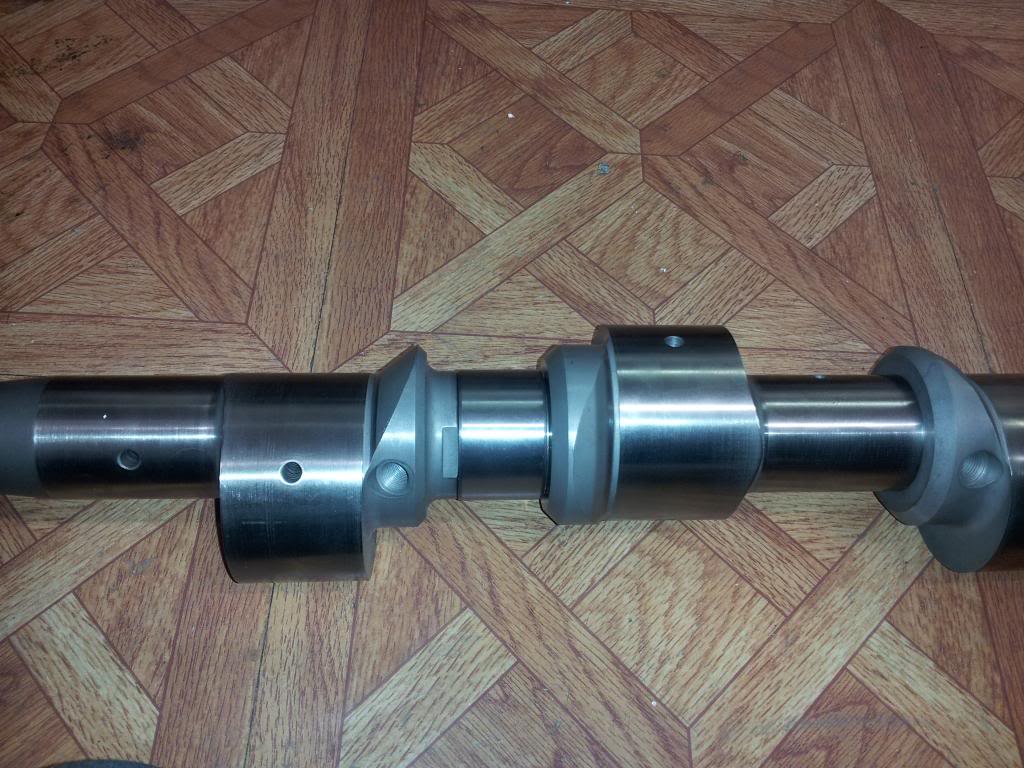
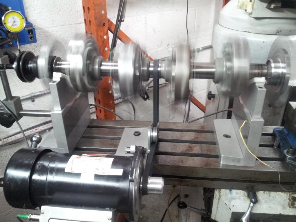
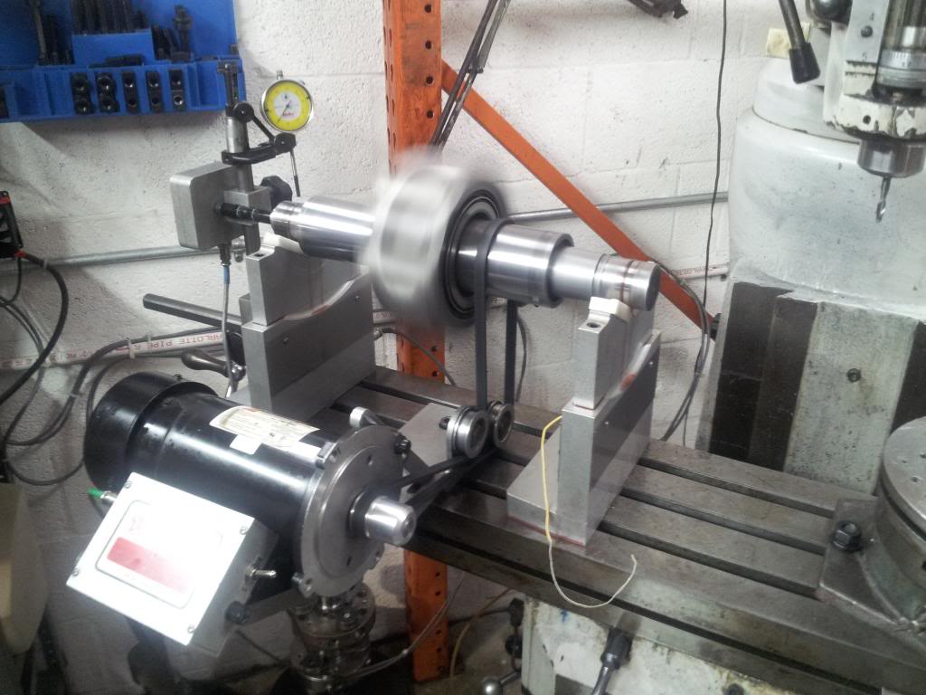
Here it is being balanced at CLR.
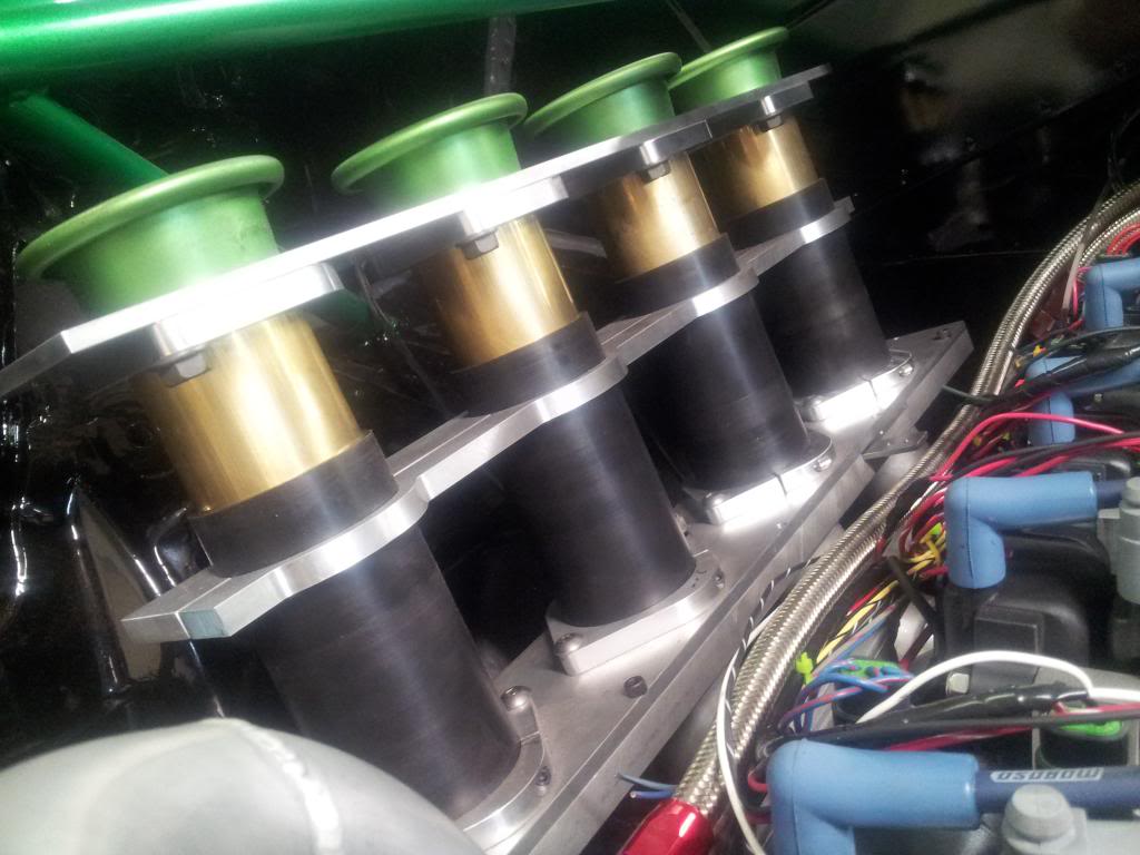
Another shot of the intake, Also some wiring in the works
#56
Wastegate John
iTrader: (13)
Join Date: Feb 2008
Location: Long Island NY 11746
Posts: 2,979
Likes: 0
Received 9 Likes
on
9 Posts
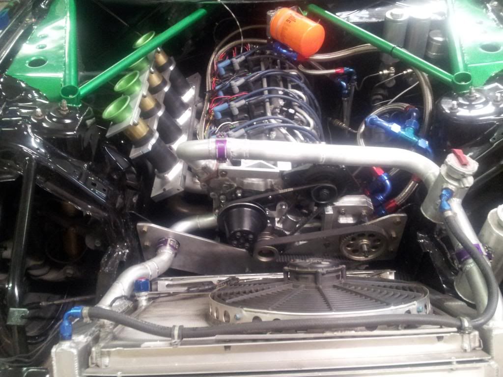
Logan, on the other forum you posted pic showing the radiator coolant lines. The lower one has no ability to flex even with the wiggins coupling. I would be concerned with a coolant leak due to cracking. Unless this is just a temp setup until you install an EWP as I assume you will.
Last edited by RENESISFD; 06-13-13 at 02:00 PM.
#58
Logan, on the other forum you posted pic showing the radiator coolant lines. The lower one has no ability to flex even with the wiggins coupling. I would be concerned with a coolant leak due to cracking. Unless this is just a temp setup until you install an EWP as I assume you will.
His engine is solidly mounted therefore, no torque twist at the radiator lines.
#62
Bump'n it and joining the thread.
I'm kinda with Big John on the coolant hoses. Chassis and engine vibration "could" certainly cause some cracking IMO. The current setup would make me very nervous. Even a very short hose length to give you some dampening would be ideal I would think, but hey, I'm all ears.
I'm kinda with Big John on the coolant hoses. Chassis and engine vibration "could" certainly cause some cracking IMO. The current setup would make me very nervous. Even a very short hose length to give you some dampening would be ideal I would think, but hey, I'm all ears.
#65
The torque is what twist the chassis and even a NA 4 rotor doesn't have a hugh amount of torque. Don't get me wrong but I too was a little worried when I saw it. I'm sure he's thought about that. He's also got quite a bit chassis reinforcement/bracing so I guess we'll find out. If you don't experiment, you will never know.

#66
Wastegate John
iTrader: (13)
Join Date: Feb 2008
Location: Long Island NY 11746
Posts: 2,979
Likes: 0
Received 9 Likes
on
9 Posts
There are certainly more forces acting on the engine and chassis than just engine torque. There is a ton of twisting and flexing forces applied to the chassis due to the large amount of force transferred through the chassis due to the wide slicks and significant down-force this car will produce extremely high cornering g's that will transfer to high chassis loads. Even with all of that additional bracing the chassis WILL flex. It will not be a lot but all it takes is 1 millimeter or 2 over an extended period to fatigue and crack the aluminum. Since this is an endurance engine that is intended to compete in many endurance races this is certainly a plausible scenario.
It is also just not sound engineering practice to deliberately not allow for flex based on the assumption that there will be none.
The top radiator "hose" has plenty of room for flex it is just the bottom one that concerns me.
However, all of this may be a moot point because I think I spy an additional clamp behind the water pump pulley but I am not sure.
#68
There are certainly more forces acting on the engine and chassis than just engine torque. There is a ton of twisting and flexing forces applied to the chassis due to the large amount of force transferred through the chassis due to the wide slicks and significant down-force this car will produce extremely high cornering g's that will transfer to high chassis loads. Even with all of that additional bracing the chassis WILL flex. It will not be a lot but all it takes is 1 millimeter or 2 over an extended period to fatigue and crack the aluminum. Since this is an endurance engine that is intended to compete in many endurance races this is certainly a plausible scenario.
It is also just not sound engineering practice to deliberately not allow for flex based on the assumption that there will be none.
The top radiator "hose" has plenty of room for flex it is just the bottom one that concerns me.
However, all of this may be a moot point because I think I spy an additional clamp behind the water pump pulley but I am not sure.
It is also just not sound engineering practice to deliberately not allow for flex based on the assumption that there will be none.
The top radiator "hose" has plenty of room for flex it is just the bottom one that concerns me.
However, all of this may be a moot point because I think I spy an additional clamp behind the water pump pulley but I am not sure.
#69
There are certainly more forces acting on the engine and chassis than just engine torque. There is a ton of twisting and flexing forces applied to the chassis due to the large amount of force transferred through the chassis due to the wide slicks and significant down-force this car will produce extremely high cornering g's that will transfer to high chassis loads. Even with all of that additional bracing the chassis WILL flex. It will not be a lot but all it takes is 1 millimeter or 2 over an extended period to fatigue and crack the aluminum. Since this is an endurance engine that is intended to compete in many endurance races this is certainly a plausible scenario.
It is also just not sound engineering practice to deliberately not allow for flex based on the assumption that there will be none.
The top radiator "hose" has plenty of room for flex it is just the bottom one that concerns me.
However, all of this may be a moot point because I think I spy an additional clamp behind the water pump pulley but I am not sure.
It is also just not sound engineering practice to deliberately not allow for flex based on the assumption that there will be none.
The top radiator "hose" has plenty of room for flex it is just the bottom one that concerns me.
However, all of this may be a moot point because I think I spy an additional clamp behind the water pump pulley but I am not sure.
You can still engineer around the flex with a floating radiator mounting system that allows for some give. I look at it this way. Solidly mount the radiator and allow flex with the hoses or you can do the opposite and float/dampin the mounting of the radiator so you can run the hard lines. Either way should work. You'll never know unless you try it. I mean I love that he's trying to find a way to eliminate any chance of a ruptured hose.
#70
Wastegate John
iTrader: (13)
Join Date: Feb 2008
Location: Long Island NY 11746
Posts: 2,979
Likes: 0
Received 9 Likes
on
9 Posts
^ It will still apply a ton of undue stress at the radiator piping.
"I mean I love that he's trying to find a way to eliminate any chance of a ruptured hose."
I've done that already.
"I mean I love that he's trying to find a way to eliminate any chance of a ruptured hose."
I've done that already.
#74
Rotary Enthusiast
love the intake


