
Home brew 2jz

Thread Starter
Full Member
Joined: Dec 2011
Posts: 74
Likes: 0
From: England
Home brew 2jz
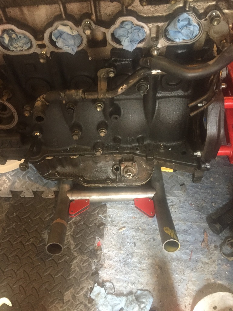
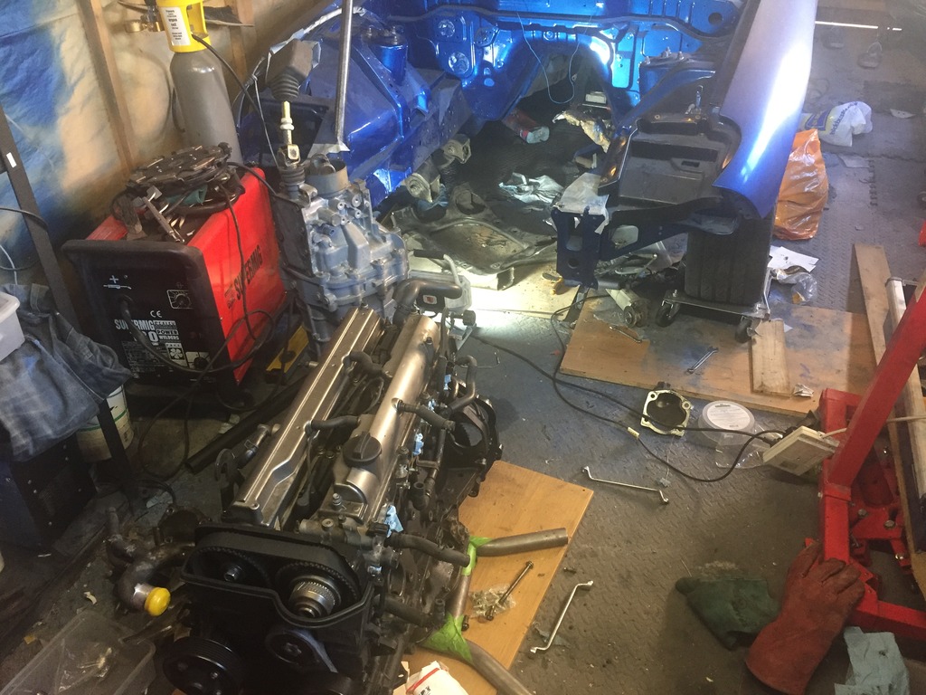
So even though I'm keeping the twins and all the OEM manifolds and bits, for the time being it's ALOT easier to strip it all off so i can do teh fabrication to mount the engine.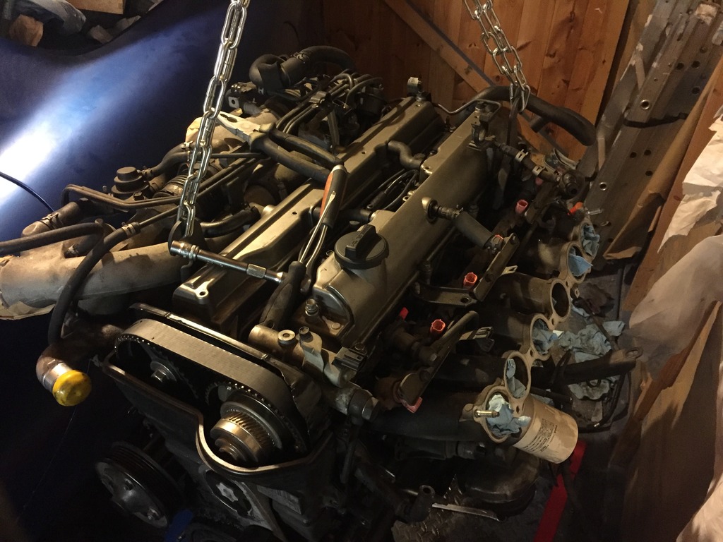
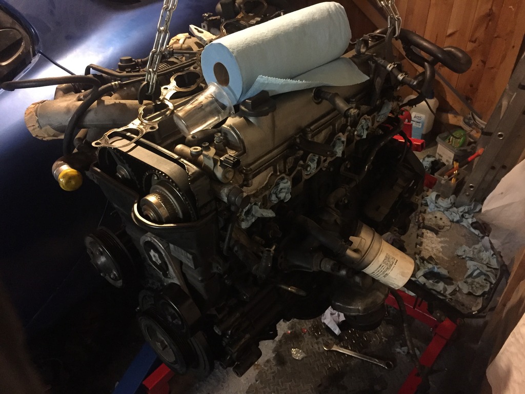
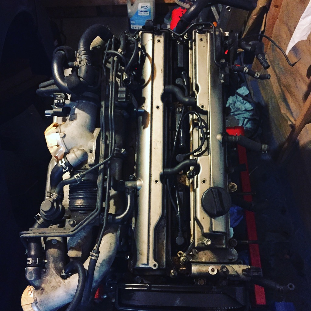
Removing the twin turbo's gave me horrible flash backs of removing the twins from the 13b many years ago. So glad i didnt have to remove these while the engine was inside of a bag! Pain in the ***!!
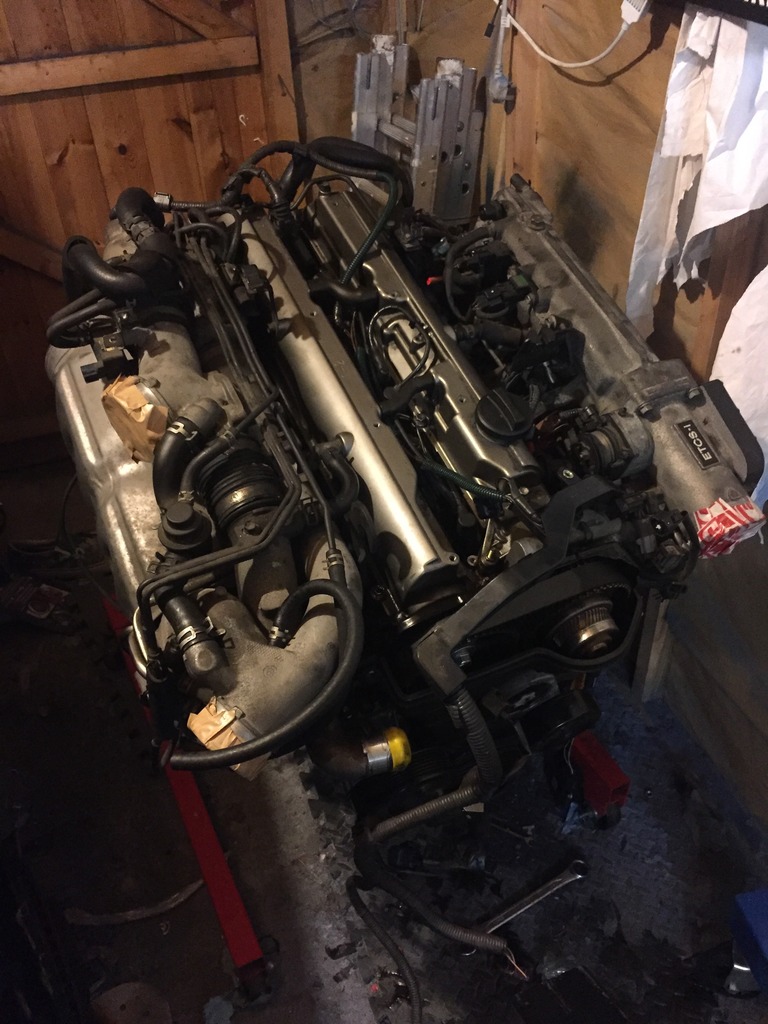
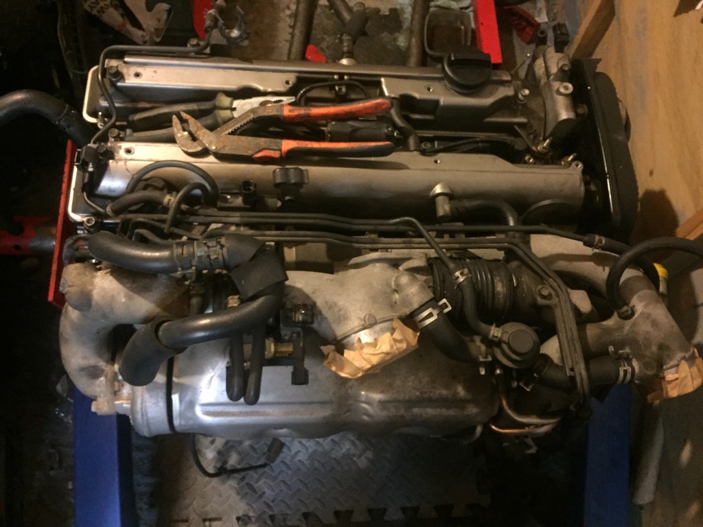
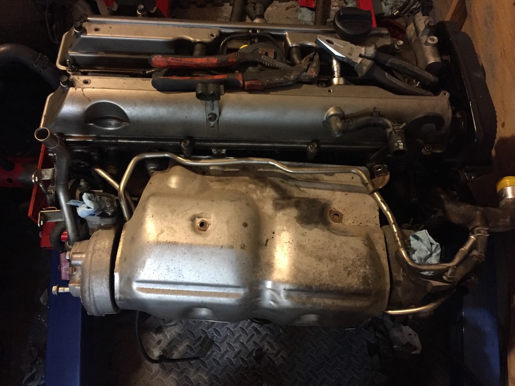
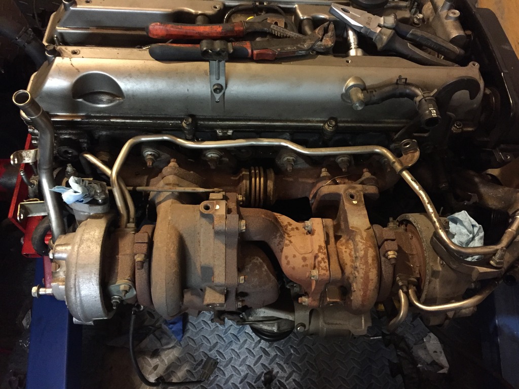
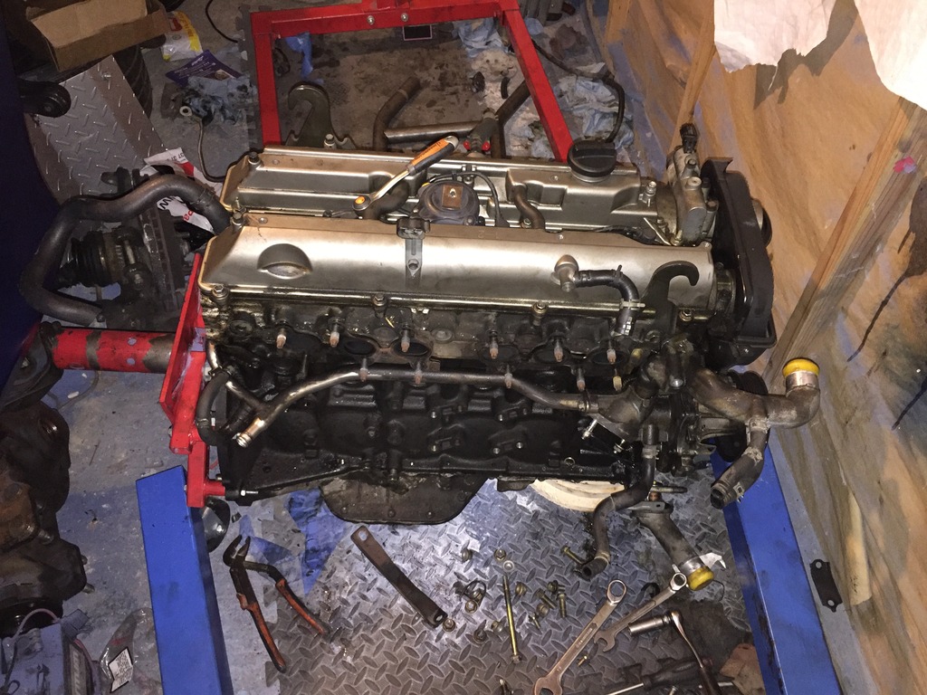
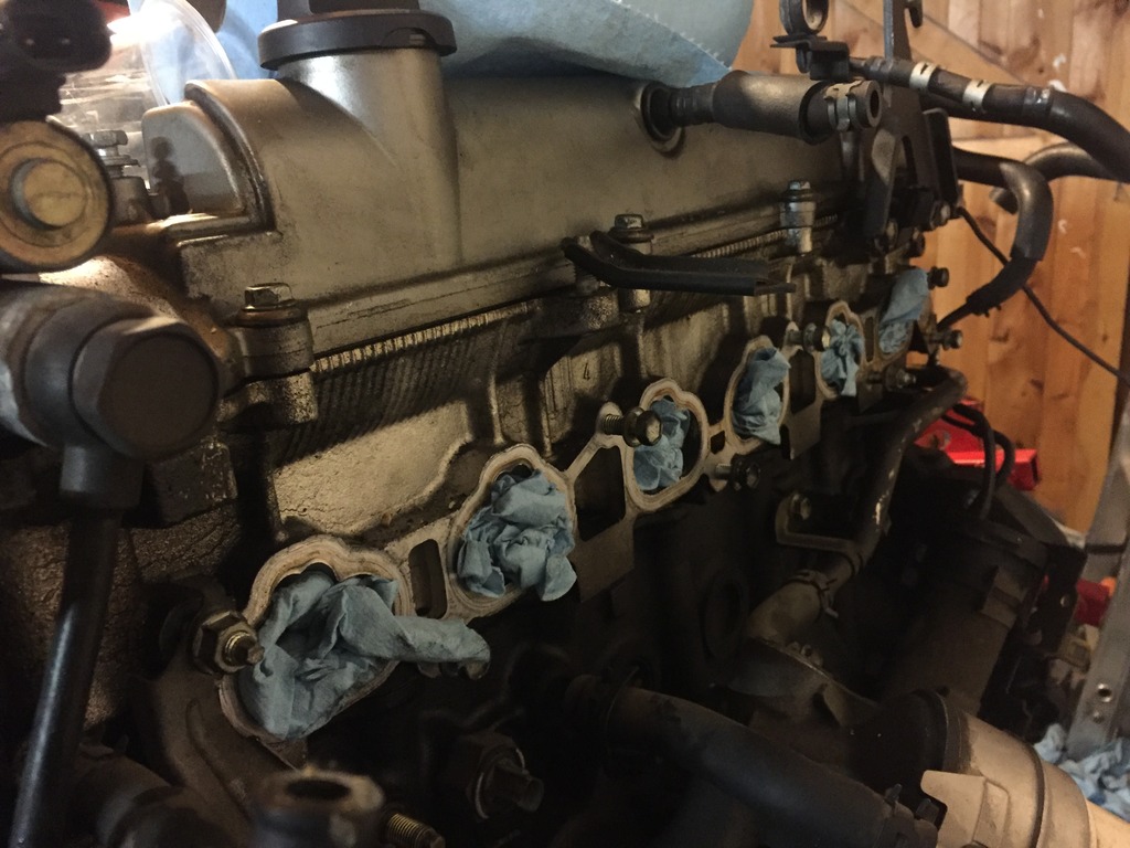
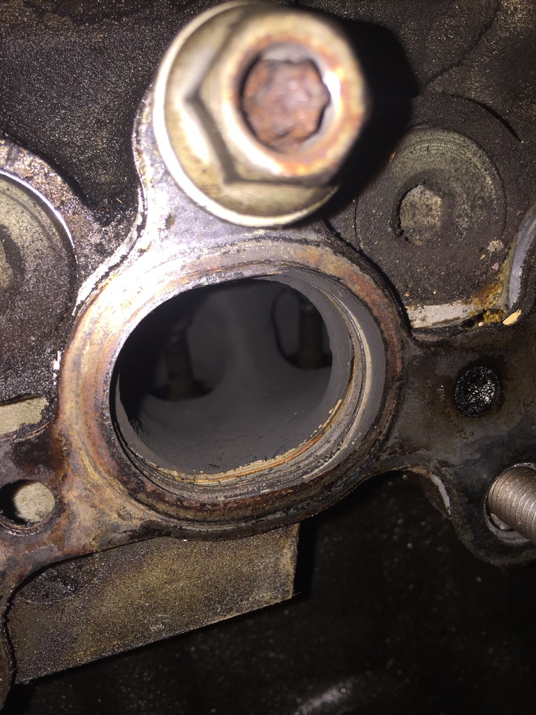
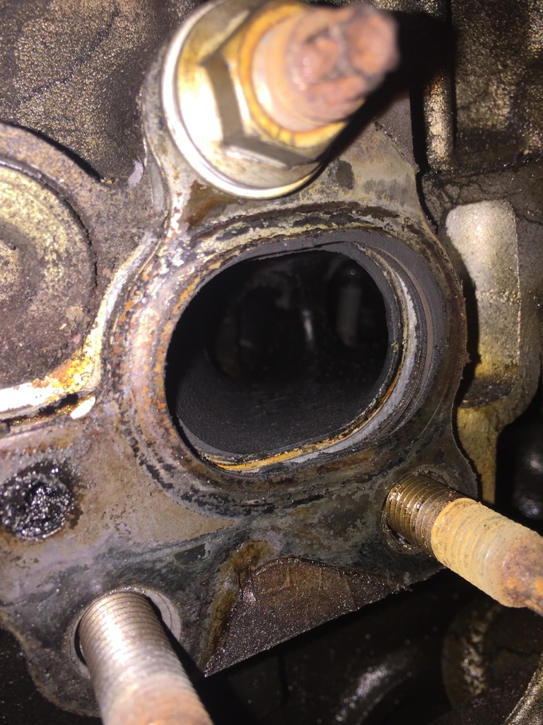
Any while the manifold is off it's a chance to take a look inside.. apex seals look a bit strange?!
Removing the twin turbo's gave me horrible flash backs of removing the twins from the 13b many years ago. So glad i didnt have to remove these while the engine was inside of a bag! Pain in the ***!!
Any while the manifold is off it's a chance to take a look inside.. apex seals look a bit strange?!
Thread Starter
Full Member
Joined: Dec 2011
Posts: 74
Likes: 0
From: England
engine mounting....
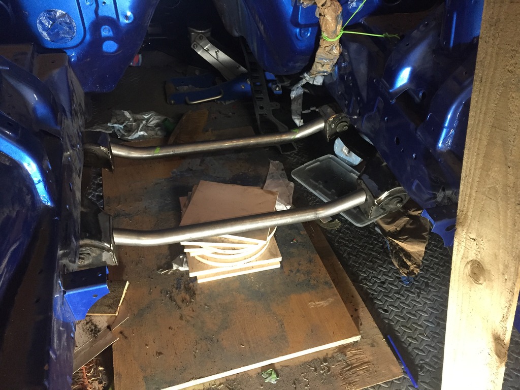
Mandrel bent CDS steel tubing and notched tubes for cross members. I had debated using a "pipe bender" and making these myself, but having done a couple of test runs i thought better of it! These were supplied by tube-bender.co.uk,
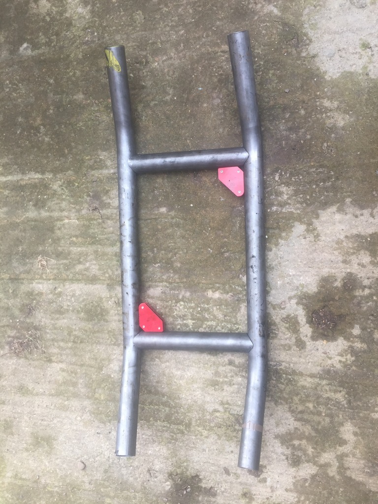
Fits perfectly around the sump
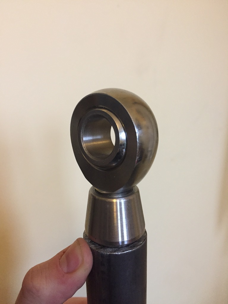
As well as a custom subframe, I'm also ditching the OEM engine mounts in favour of an ALMOST solid mound. I'm using 3/4" rose joints which will be bolted to the sub frame cross members.
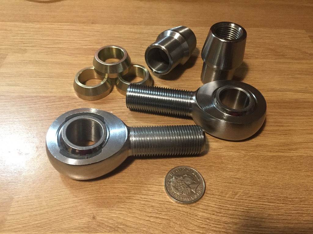
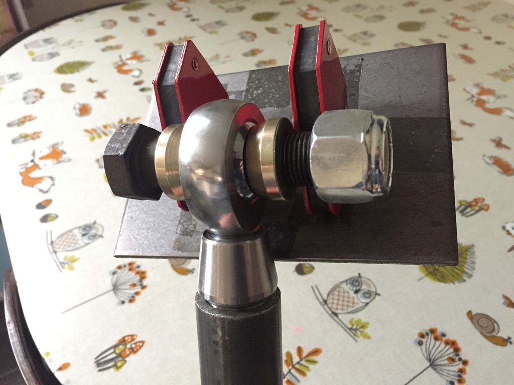
Here's the mock up of the mounting tabs which the rose joints will be bolted to:
more soon...:p
Mandrel bent CDS steel tubing and notched tubes for cross members. I had debated using a "pipe bender" and making these myself, but having done a couple of test runs i thought better of it! These were supplied by tube-bender.co.uk,
Fits perfectly around the sump
As well as a custom subframe, I'm also ditching the OEM engine mounts in favour of an ALMOST solid mound. I'm using 3/4" rose joints which will be bolted to the sub frame cross members.
Here's the mock up of the mounting tabs which the rose joints will be bolted to:
more soon...:p
Thread Starter
Full Member
Joined: Dec 2011
Posts: 74
Likes: 0
From: England
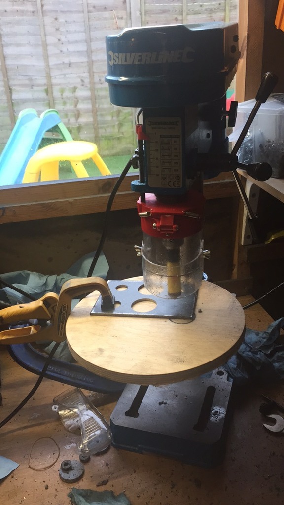
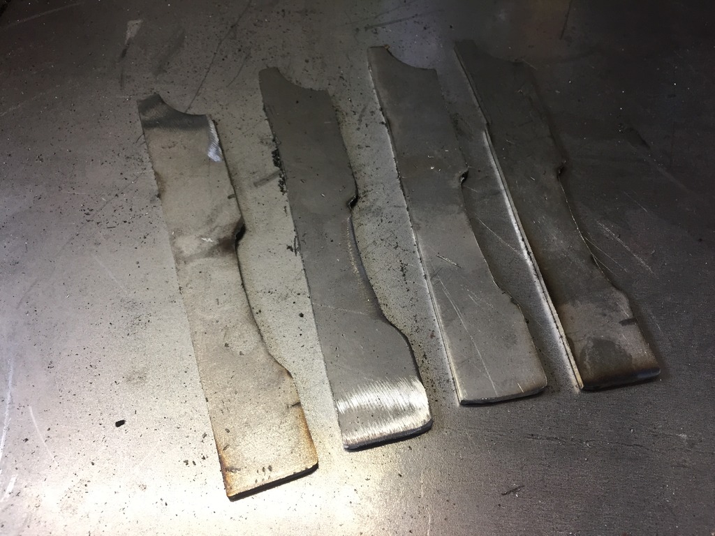
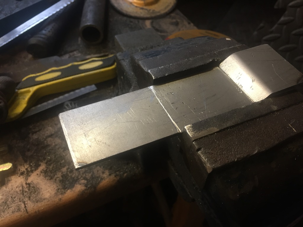
Got a little more garage time and using my new mini bench drill and some hole saw bits i cut out the engine mount tabs:
As you can see, a LARGE amount of cutting oil was used
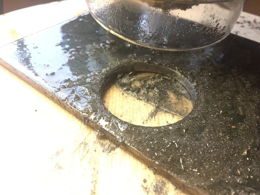
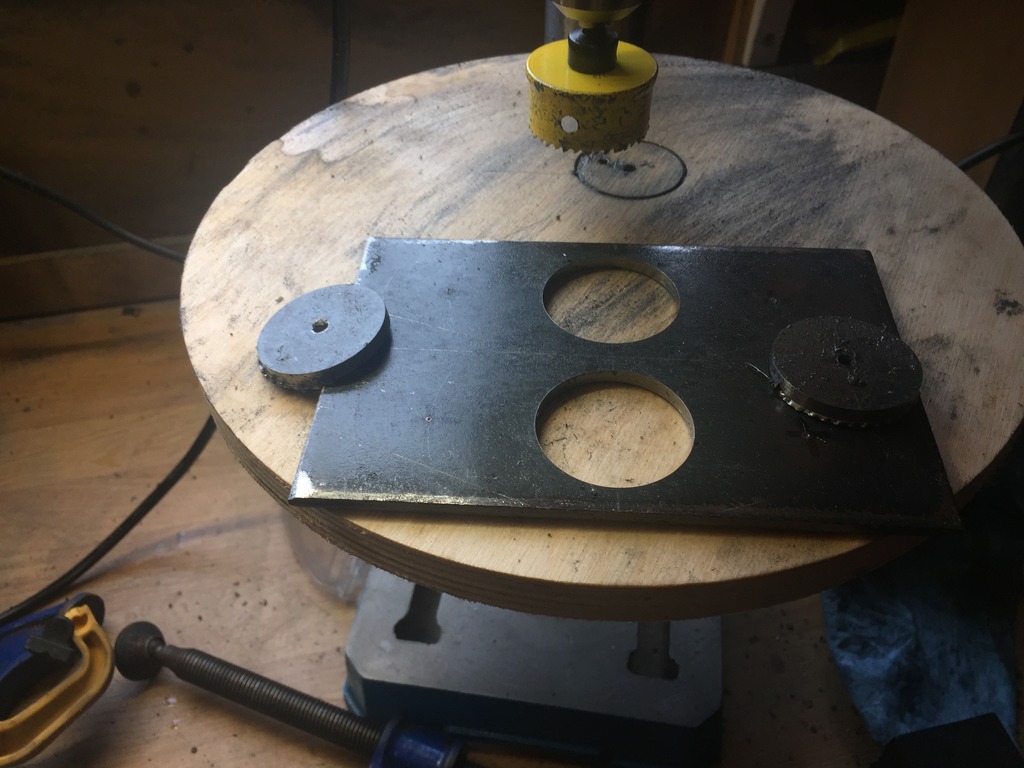
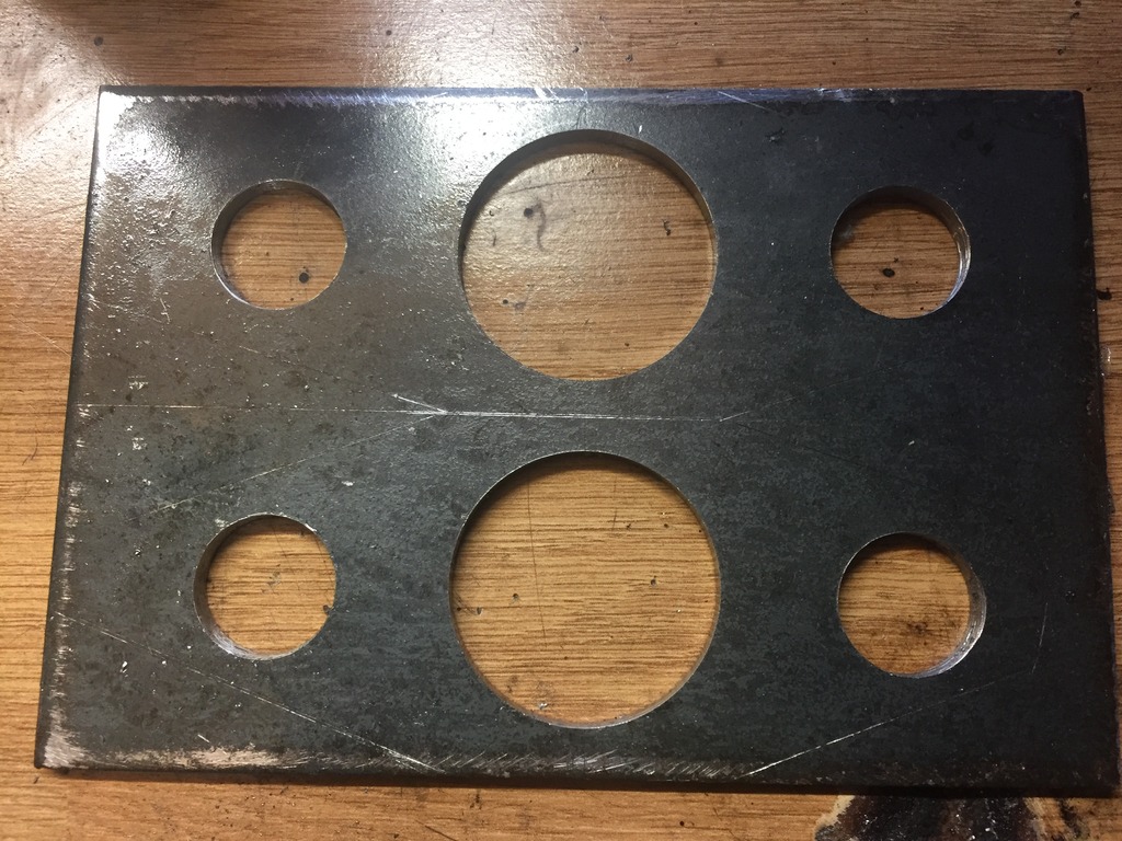
This is the end result, they need a tidy up final couple of cuts and a side up to finish off but you get the general idea.
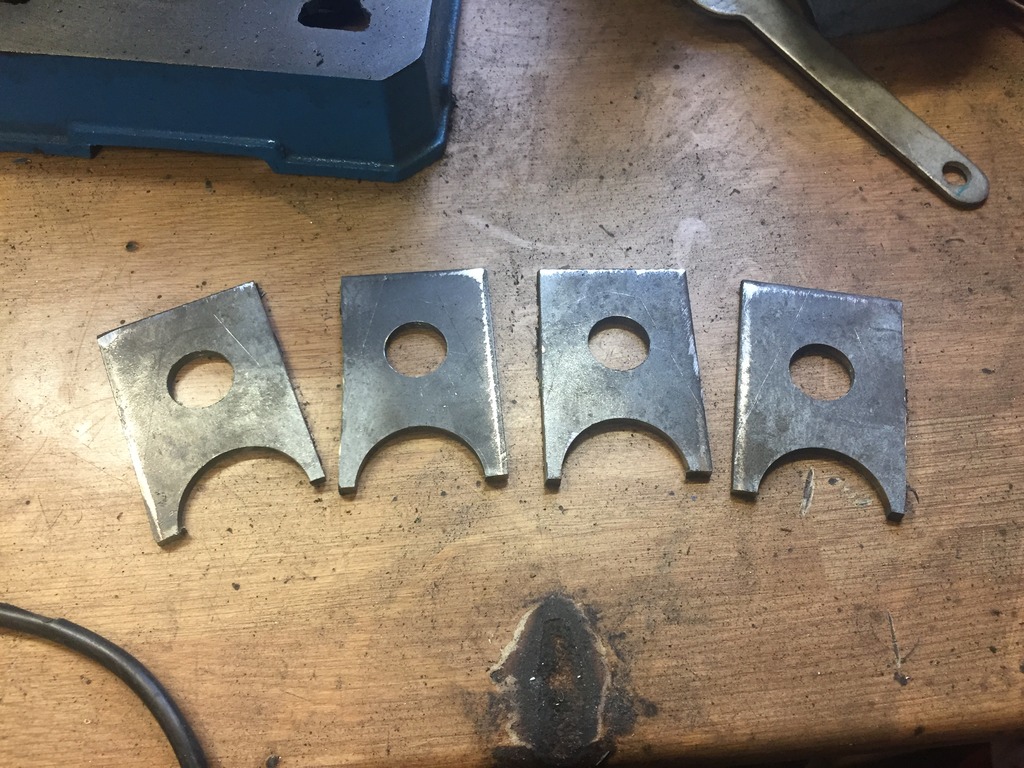
Next on the shopping list is a chop saw which i need for cutting the ends short for the tubular subframe and also for the the 4mm wall tube which will go between the rose joints and the engine block for the mounts.
As you can see, a LARGE amount of cutting oil was used
This is the end result, they need a tidy up final couple of cuts and a side up to finish off but you get the general idea.
Next on the shopping list is a chop saw which i need for cutting the ends short for the tubular subframe and also for the the 4mm wall tube which will go between the rose joints and the engine block for the mounts.
Thread Starter
Full Member
Joined: Dec 2011
Posts: 74
Likes: 0
From: England
Cheers for the mixed feedback guys, i expected nothing else 
Some minor progress:
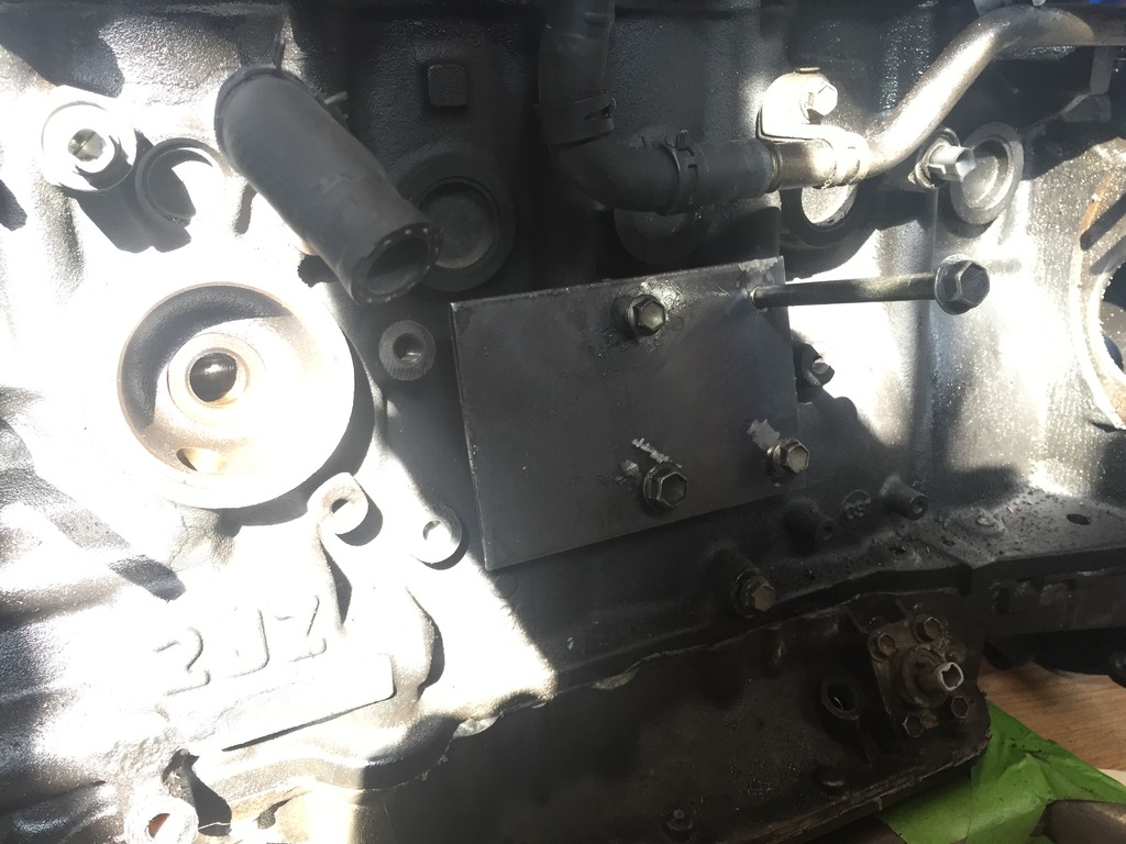
After working out where where the new engine mounts could line up i made one of the new base plates from 4mm steel, should be tough enough.
Next on the agenda was cutting the subframe apart ready for the test fit and fab work. I quickly made a note of the steering rack position so i can mount as close to the original position as possible, or at least compensate later on with alternative track rod ends.
AND THEN I CUT... no going back now!
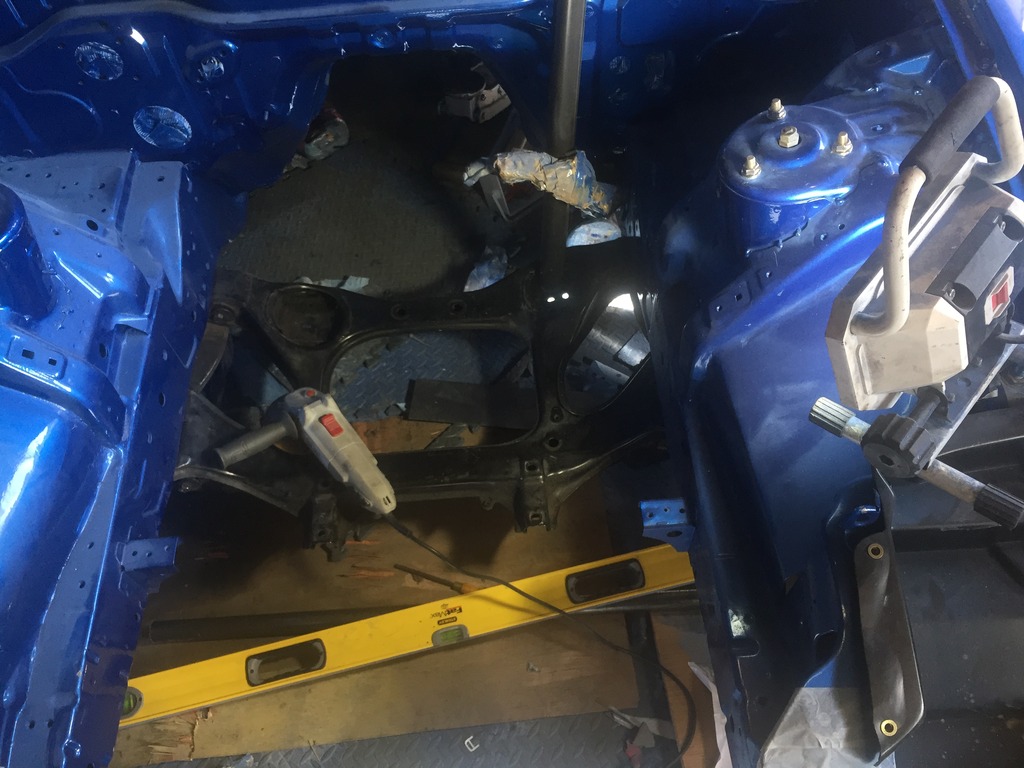
Getting the angle grinder in to the right position was actually a complede SOD withe arms in place, so i had to go old school with a hack saw at the end
BOOM!
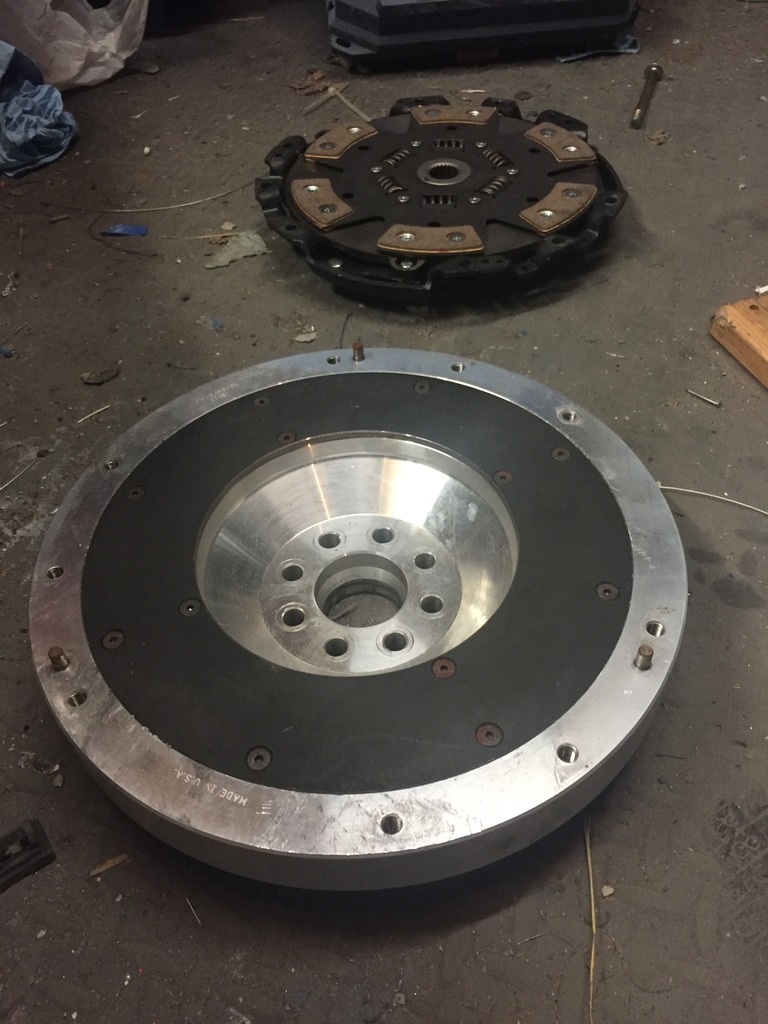
Next jobs are to assemble the collins motorsport clutch kit and Z33 gearbox and then i can do a test run of fitting. It'll be the first time i get to see if the gearbox actually fits within the transmission tunnel and where exactly the shifter ends up. I'm expecting to need a "mid mount" shifter to bring it forward by 20-30cm.
Some minor progress:
After working out where where the new engine mounts could line up i made one of the new base plates from 4mm steel, should be tough enough.
Next on the agenda was cutting the subframe apart ready for the test fit and fab work. I quickly made a note of the steering rack position so i can mount as close to the original position as possible, or at least compensate later on with alternative track rod ends.
AND THEN I CUT... no going back now!
Getting the angle grinder in to the right position was actually a complede SOD withe arms in place, so i had to go old school with a hack saw at the end
BOOM!
Next jobs are to assemble the collins motorsport clutch kit and Z33 gearbox and then i can do a test run of fitting. It'll be the first time i get to see if the gearbox actually fits within the transmission tunnel and where exactly the shifter ends up. I'm expecting to need a "mid mount" shifter to bring it forward by 20-30cm.
Thread Starter
Full Member
Joined: Dec 2011
Posts: 74
Likes: 0
From: England
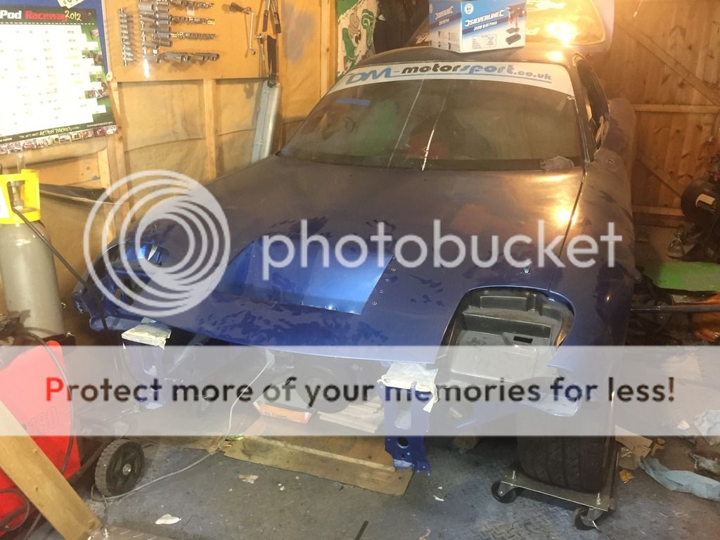
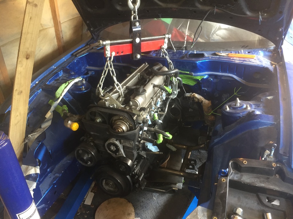
Engine is roughly in position where I'll be doing the subframe welding and even with my stupid bonnet scoop still in place... I can close the hood! GREAT SUCESS!

In other news the gearbox fits comfortably within the transmition tunnel and as predicted the shifter needs modification.

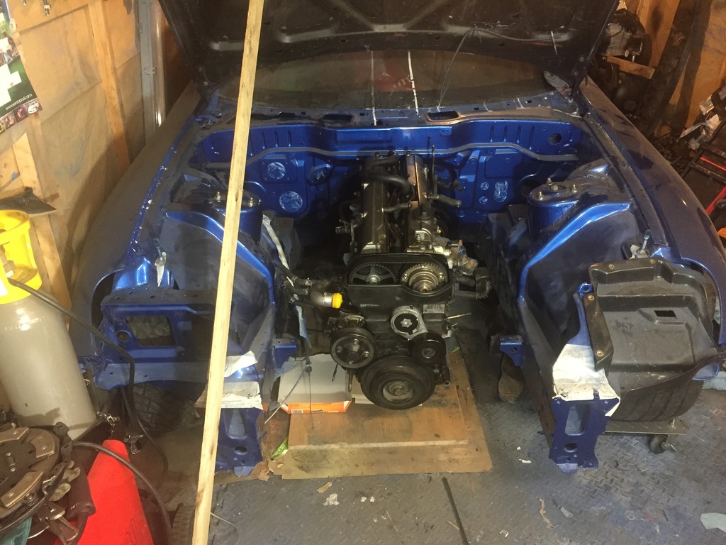
In other news the gearbox fits comfortably within the transmition tunnel and as predicted the shifter needs modification.
Thread Starter
Full Member
Joined: Dec 2011
Posts: 74
Likes: 0
From: England
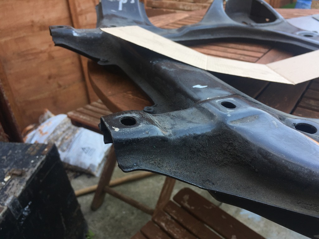
Minor update, I've managed to cut out the end plates for the subframe from 3mm steel sheet after making some cardboard templates.
With a bit of a grind down of the remaining subframe supports they seem to go on flush more or less. So now I'm into tacking them in place ready for the tubular mid section to come in.
I also had a little pacetice run at the welding using the dead half o of the subframe.... obviously practice makes perfect so I'll be doing a few more practice runs haha
Thread Starter
Full Member
Joined: Dec 2011
Posts: 74
Likes: 0
From: England
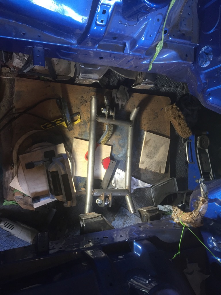
More , I now have a tacked together subframe!
Just need to cut the two lengths of 4mm wall tube that go between the rose joints and the engine mount plates, tack those together and then its welding time to attempt to weld it well enough to survive abuse :-/


Just need to cut the two lengths of 4mm wall tube that go between the rose joints and the engine mount plates, tack those together and then its welding time to attempt to weld it well enough to survive abuse :-/
Trending Topics
Thread Starter
Full Member
Joined: Dec 2011
Posts: 74
Likes: 0
From: England
Sooooo... had a slight issue with the fabrication. I had placed teh engine in teh desired location and then spot welded the new subframe around the sump. All good... until i realised i could no longer remove the engine from the bay without dropping the subframe off the car entire. FML!
Needless to say i had to chop out the subframe and start again with positioning, this time an inch further forward and hey presto the engine (with gearbox attached) can be hoisted in and out of the bay! :thumbsup:
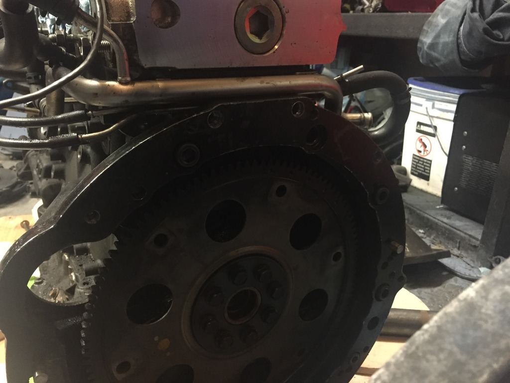
The sad news however is that in attempting to remove the engine i had to cut part of the bay (the lip above the flywheel) and had as such destroyed the lovely fresh blue paint job, so that will need to be redone at some point
The bolts i had with my collins adapter plate were also causing me some grief as the heads were too large meaning i ended up with a 3mm gap between the bell housing and the adapter plate.
Luckily the alan heads had sufficient spare depth that i could shave these down to rectify the issue.
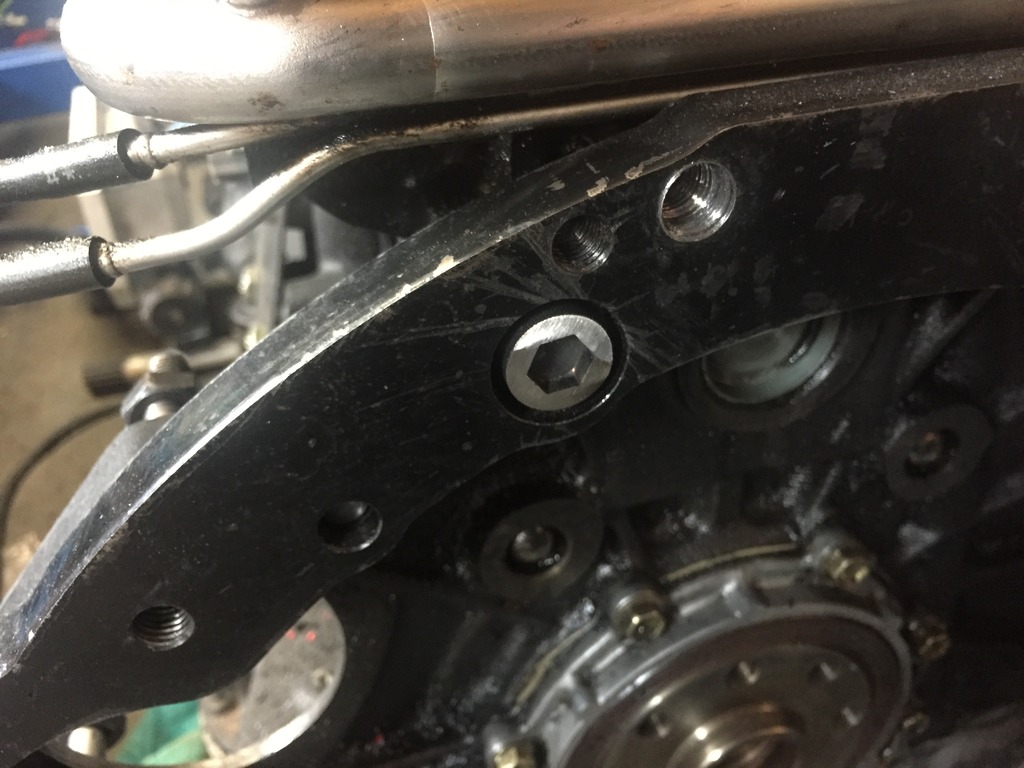
Needless to say i had to chop out the subframe and start again with positioning, this time an inch further forward and hey presto the engine (with gearbox attached) can be hoisted in and out of the bay! :thumbsup:
The sad news however is that in attempting to remove the engine i had to cut part of the bay (the lip above the flywheel) and had as such destroyed the lovely fresh blue paint job, so that will need to be redone at some point
The bolts i had with my collins adapter plate were also causing me some grief as the heads were too large meaning i ended up with a 3mm gap between the bell housing and the adapter plate.
Luckily the alan heads had sufficient spare depth that i could shave these down to rectify the issue.
Thread Starter
Full Member
Joined: Dec 2011
Posts: 74
Likes: 0
From: England
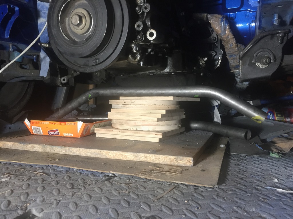
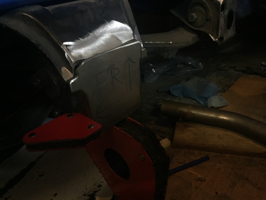
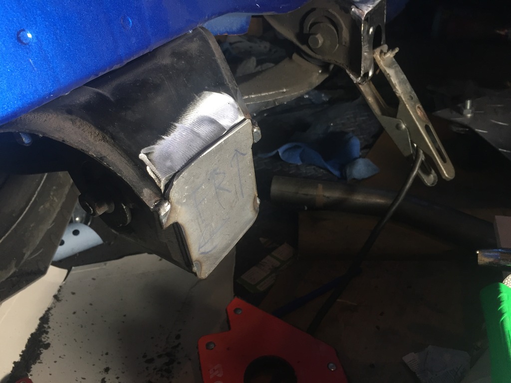
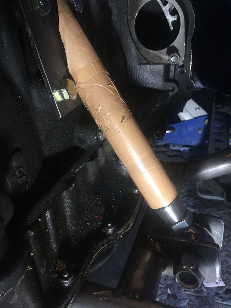
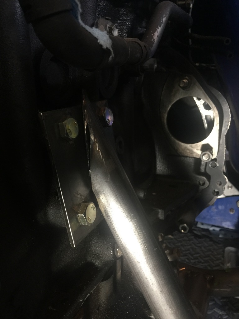
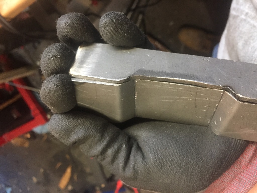
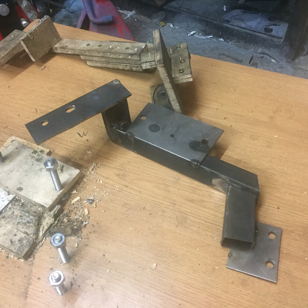
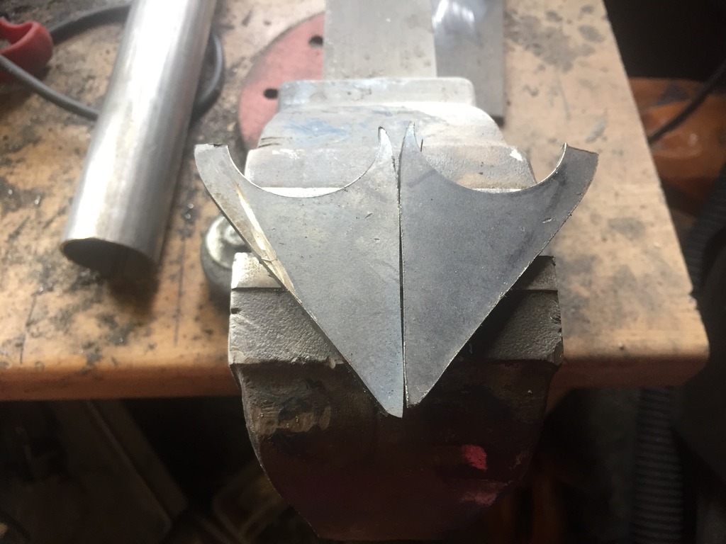
Now that the engine was in place (and more importantly removable) i set about making the 4mm wall engine mounts which connect between the engine block (3mm plate) and the subframe (3/4" rose joints)
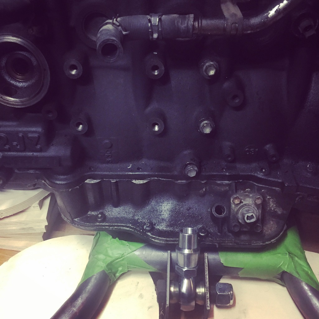
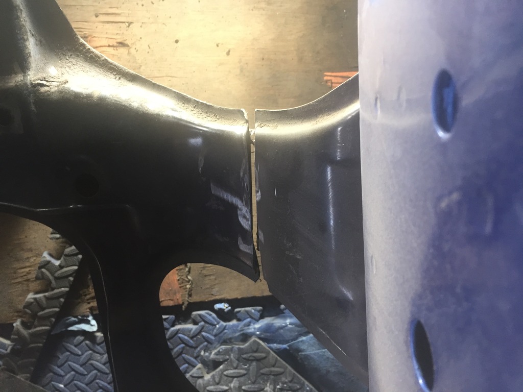
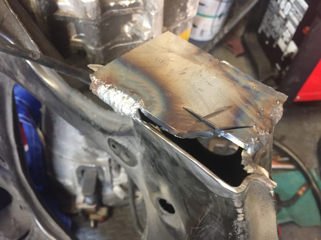
These were a complete ****** to make with teh correct angle I've no chop saw, and no easy way of measuring the angle. Here's my first abandoned attempt:
MIND THE GAP
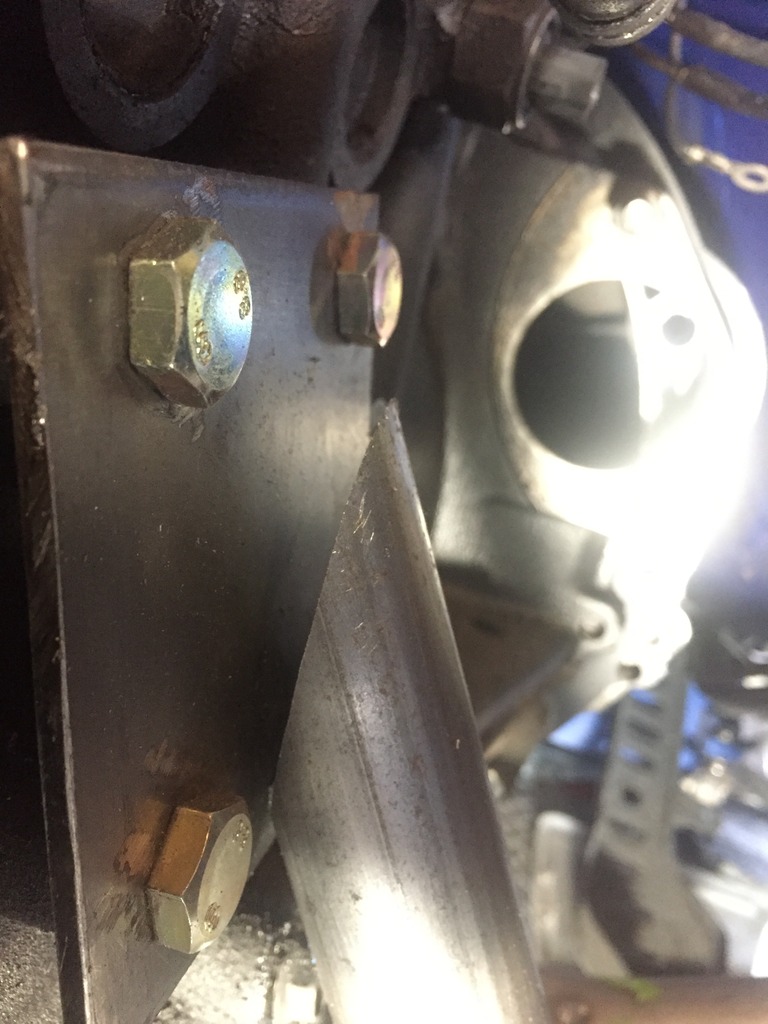
So after experimenting with cardboard and paper as a template i eventually got something flush enough to work with:
Cutting from a single length of CDS tube meant that the one template served to also make up the other side perfectly with a slightly altered length:
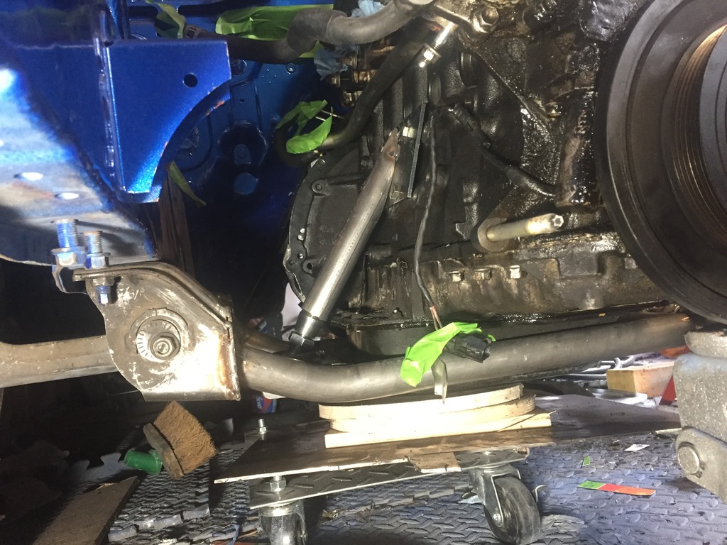
So i've just got to to a few final welds and that's the engine mounted, boom! Next onto the gearbox mount which means i need to get the car safely onto axle stands so i can get under there
These were a complete ****** to make with teh correct angle I've no chop saw, and no easy way of measuring the angle. Here's my first abandoned attempt:
MIND THE GAP
So after experimenting with cardboard and paper as a template i eventually got something flush enough to work with:
Cutting from a single length of CDS tube meant that the one template served to also make up the other side perfectly with a slightly altered length:
So i've just got to to a few final welds and that's the engine mounted, boom! Next onto the gearbox mount which means i need to get the car safely onto axle stands so i can get under there
Thread Starter
Full Member
Joined: Dec 2011
Posts: 74
Likes: 0
From: England
Well there's plenty more need for the cardboard now, as I've decided to do the steering rack next and that's completely custom :-/
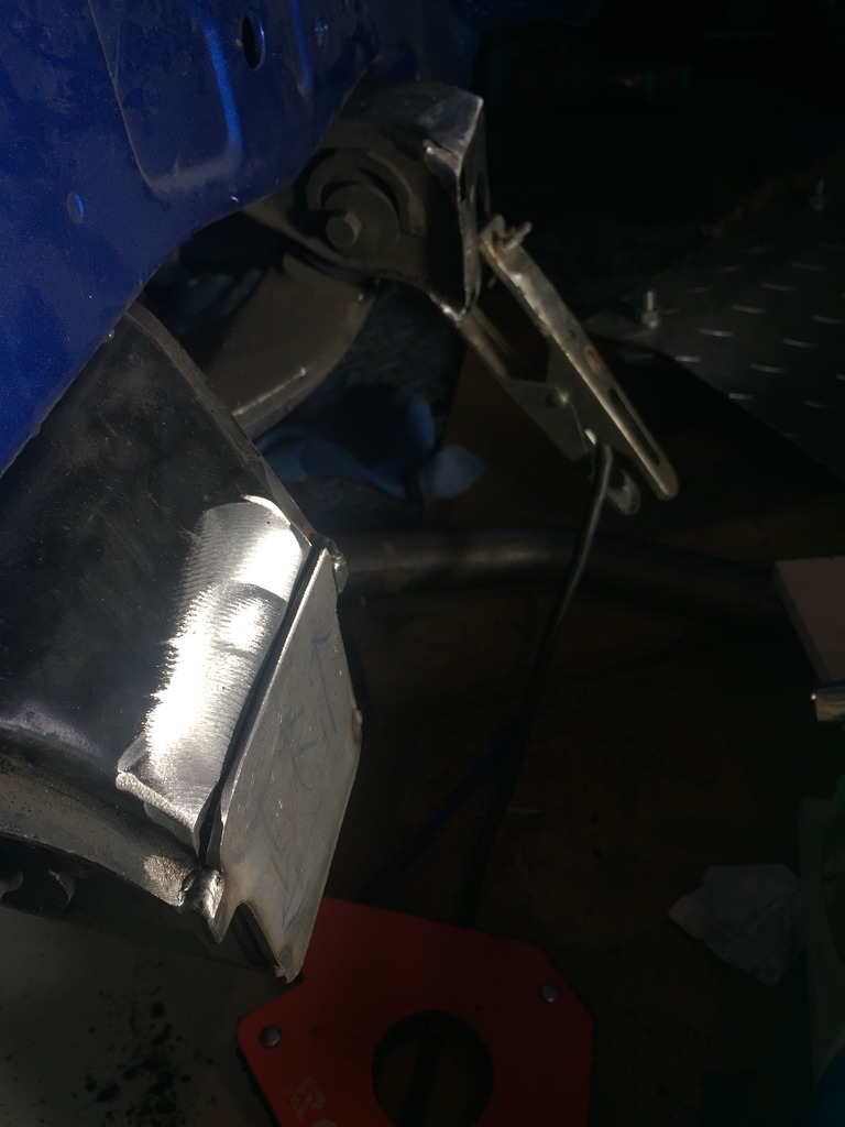
I finished welding the engine mounts, not the cleanest of welds but I'm still learning :-) the other side is worse, need an expert clean up with and angle grinder haha


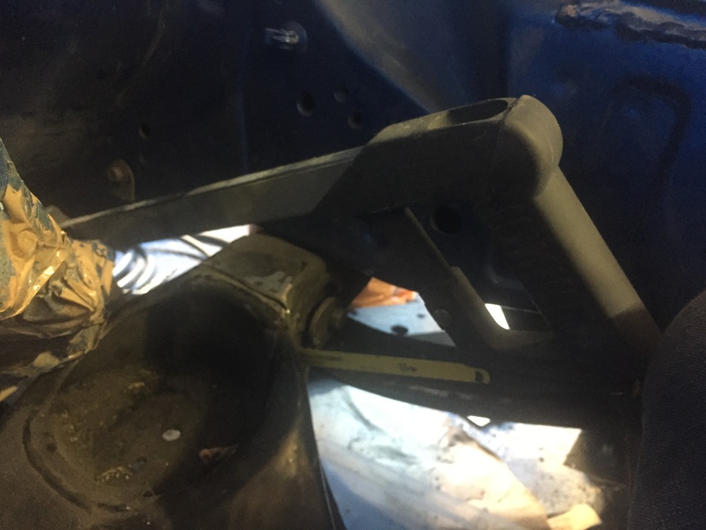
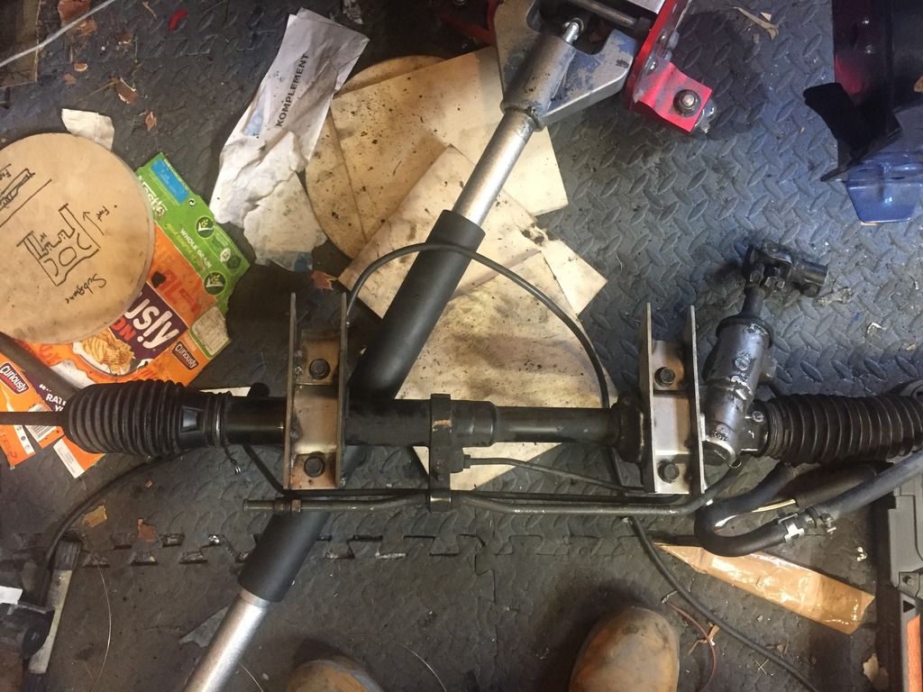
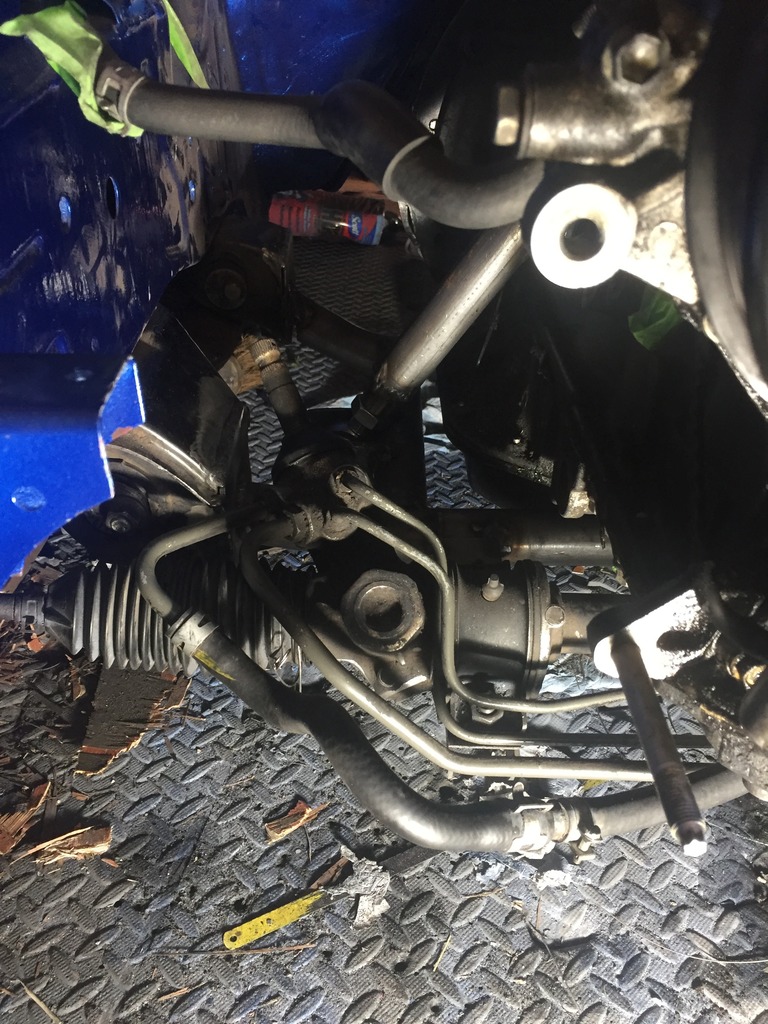
I've offered the steering rack up to the subframe to roughly work out where is CAN fit in relation tonyhebsubframe and block, then quickly checked against my measurements I made of the old location. From a front2back placement perspective it's going to be pretty close to stock. However from a height, ( which is what I believe affects bump steer? ), I haven't quite worked out the difference just yet, but there's enough room to be flexible should I need to adjust.


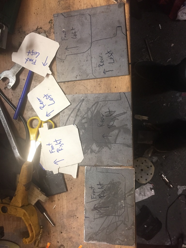
So this is what I need to re-create at a new angle on the custom subframe:
Scribbles on cardboard followed by scorning out the steel sheet ready the be cut up.


I finished welding the engine mounts, not the cleanest of welds but I'm still learning :-) the other side is worse, need an expert clean up with and angle grinder haha
I've offered the steering rack up to the subframe to roughly work out where is CAN fit in relation tonyhebsubframe and block, then quickly checked against my measurements I made of the old location. From a front2back placement perspective it's going to be pretty close to stock. However from a height, ( which is what I believe affects bump steer? ), I haven't quite worked out the difference just yet, but there's enough room to be flexible should I need to adjust.
So this is what I need to re-create at a new angle on the custom subframe:
Scribbles on cardboard followed by scorning out the steel sheet ready the be cut up.


Thread Starter
Full Member
Joined: Dec 2011
Posts: 74
Likes: 0
From: England
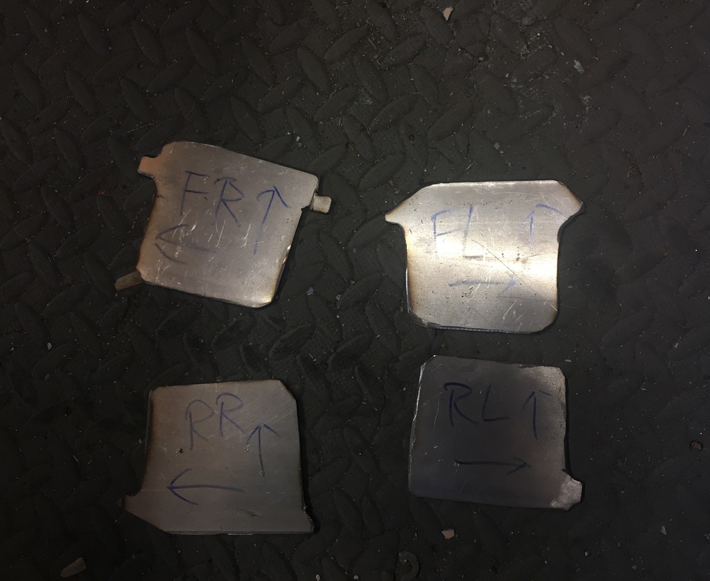
Soooo...
second time around managed to get a nicer finish to the bracket
score with a hacksaw to make the bends cleaner:
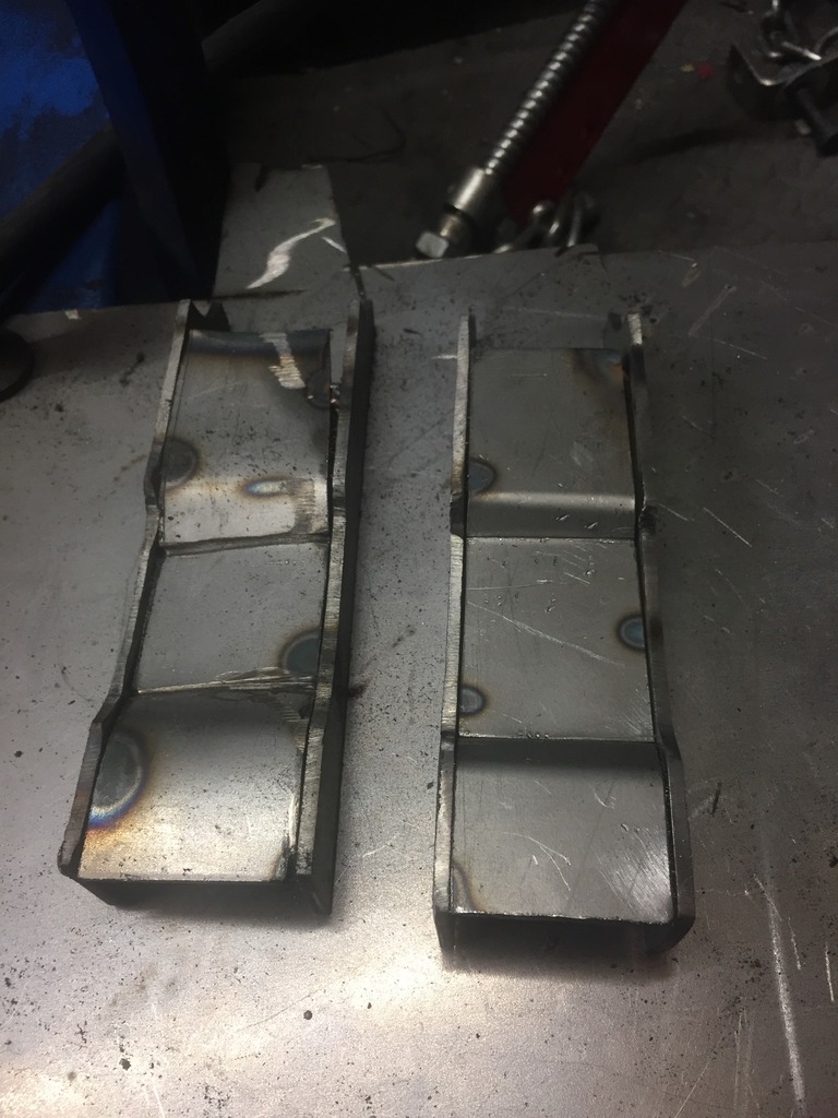
After bolting the DIY brackets to the rack and fumbling around to find the centre line i got really F'ed off because the rack was fouling the subframe at the pinion side and there was seeming no angle that i could place it at.
So i then went through modifying the rack mounts 3/4 times and eventually found the right mixture of length and angle for the brackets to give a reasonable amount of clearance :thumbsup:
Next job is the gearbox mount
second time around managed to get a nicer finish to the bracket
score with a hacksaw to make the bends cleaner:
After bolting the DIY brackets to the rack and fumbling around to find the centre line i got really F'ed off because the rack was fouling the subframe at the pinion side and there was seeming no angle that i could place it at.
So i then went through modifying the rack mounts 3/4 times and eventually found the right mixture of length and angle for the brackets to give a reasonable amount of clearance :thumbsup:
Next job is the gearbox mount
Thread Starter
Full Member
Joined: Dec 2011
Posts: 74
Likes: 0
From: England
Thread Starter
Full Member
Joined: Dec 2011
Posts: 74
Likes: 0
From: England
Once it's looking a bit more finished i'll have a look into it

Thread Starter
Full Member
Joined: Dec 2011
Posts: 74
Likes: 0
From: England
Sooooo....
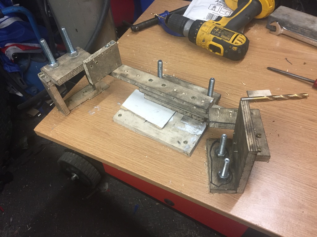
Spent some time tinkering to make up a gearbox brace and as always it's an experiment as I go
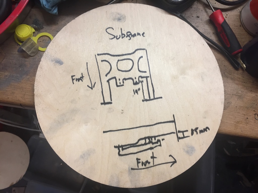
I decided that the best way to go was to make a template / jig so i could make and remake it should i need to. So save cutting holes in the tunnel wall, for teh time bing I'm sticking to just using teh standard mount points which are commonly used by dragon performance diff brace and the like. I know they are weaker and have been known to strip their thread, but mine held out before with the FD boxane because the engine is solid mounted I'm not expecting much in the way of movement
Wooden brace:
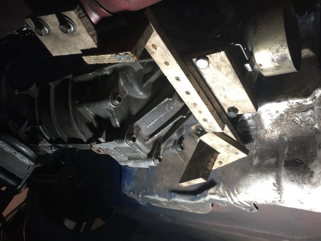
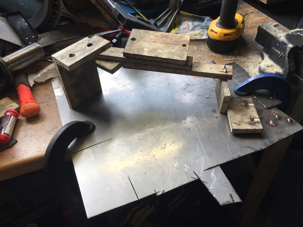
I used that to make up a jig:
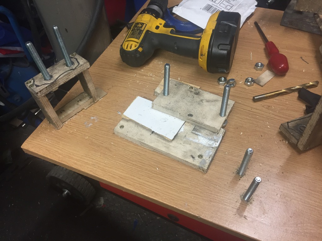
And then cut and tacked together some random box and sheet steel to make a brace. Sadly i had run out of Argon gas, so was using a gases mini mig with flux core which is NASTY, but god enough for tacking at least.
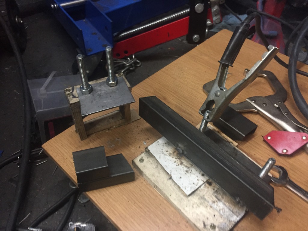
So after all that the mocked up brace fouled the gearbox and the transmission tunnel in like 3 places so i got really pissed off
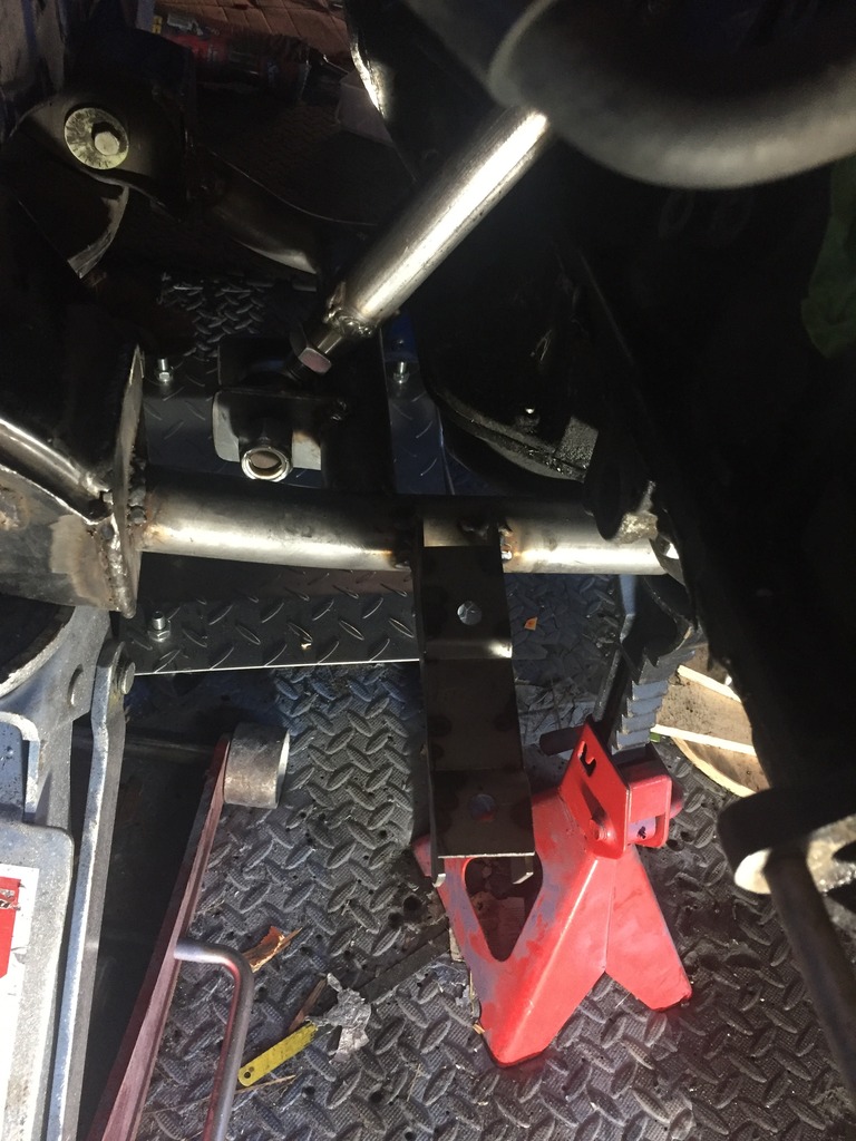
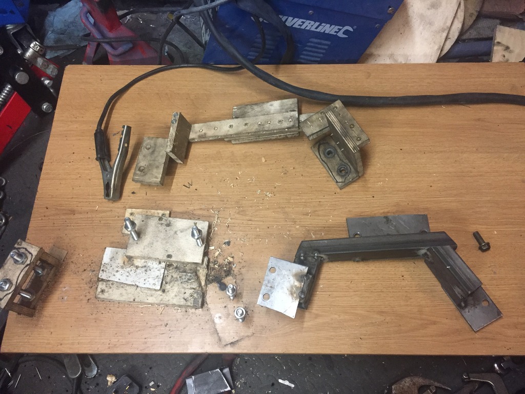
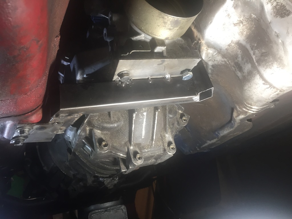
So then i abandoned the jig and did a free style fab job under the car and ended up with this:
Which OBVIOUSLY fit a treat as it was put together ON the car
Spent some time tinkering to make up a gearbox brace and as always it's an experiment as I go
I decided that the best way to go was to make a template / jig so i could make and remake it should i need to. So save cutting holes in the tunnel wall, for teh time bing I'm sticking to just using teh standard mount points which are commonly used by dragon performance diff brace and the like. I know they are weaker and have been known to strip their thread, but mine held out before with the FD boxane because the engine is solid mounted I'm not expecting much in the way of movement
Wooden brace:
I used that to make up a jig:
And then cut and tacked together some random box and sheet steel to make a brace. Sadly i had run out of Argon gas, so was using a gases mini mig with flux core which is NASTY, but god enough for tacking at least.
So after all that the mocked up brace fouled the gearbox and the transmission tunnel in like 3 places so i got really pissed off
So then i abandoned the jig and did a free style fab job under the car and ended up with this:
Which OBVIOUSLY fit a treat as it was put together ON the car
Thread Starter
Full Member
Joined: Dec 2011
Posts: 74
Likes: 0
From: England
So have been having a bit of a debate over the best way to fabricate up the diff bracing in order to replace the factory power plant frame. I'v decided to plagiarise the Dyno Torque approach, which from the research i've done is the only one that leverages a load baring mounting point on the shell.
All the others (e.g. Samberg) only use captive nuts positioned which are usually used as transmission tunnel cross members. From experience i can say that these strip under very little stress and the usual approach is to drill out and replace, but even then are known to die a horrible death.
Worth noting that my transition brace above is also a potential victim of that.. so that may be getting replaced soon enough!
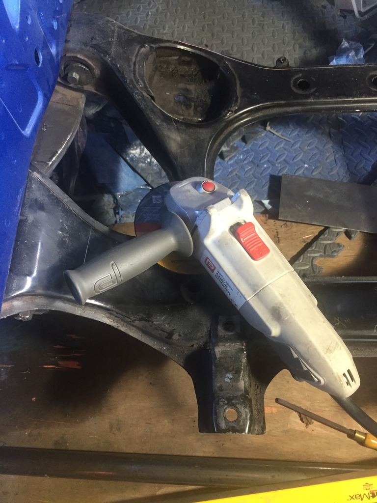
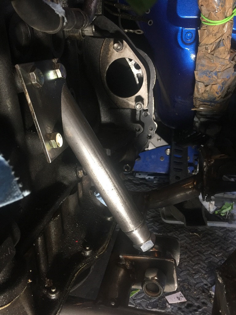
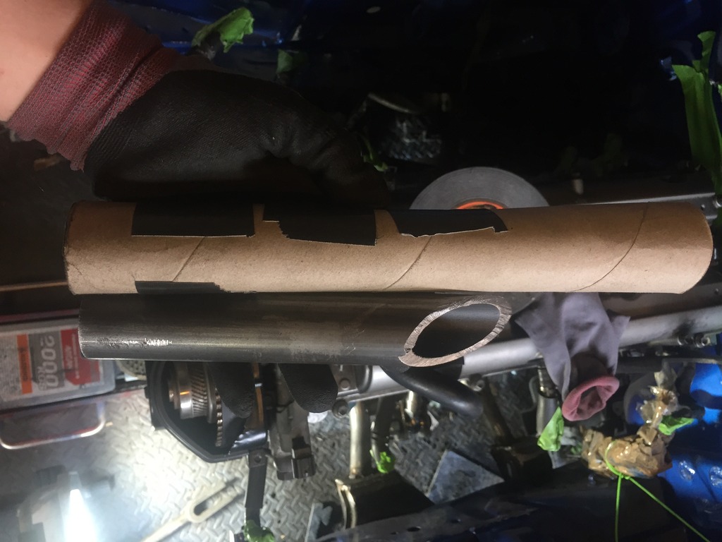
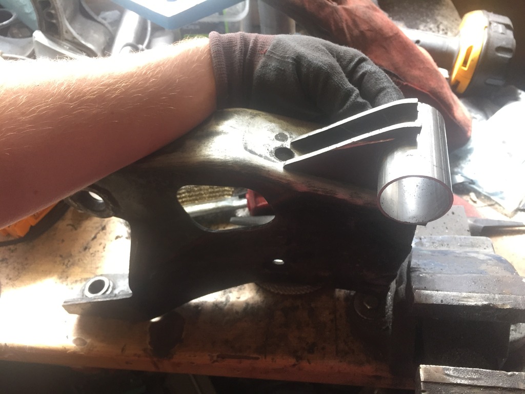
Anyway, here is what i have so far, notched the pipe with an angle grinder
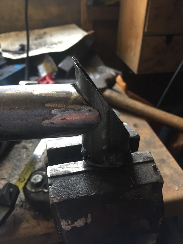
Next step is toward out how to actually attach the thing to the Diff. At the moment I'm assuming that cutting the PPF in half and attaching via some kind of bushing is going to be the best easiest way.
Also bought one of these to ensure that the diff and gearbox faces are level with each over to avoid strain on the prop shaft joints :thumbs:

All the others (e.g. Samberg) only use captive nuts positioned which are usually used as transmission tunnel cross members. From experience i can say that these strip under very little stress and the usual approach is to drill out and replace, but even then are known to die a horrible death.
Worth noting that my transition brace above is also a potential victim of that.. so that may be getting replaced soon enough!
Anyway, here is what i have so far, notched the pipe with an angle grinder
Next step is toward out how to actually attach the thing to the Diff. At the moment I'm assuming that cutting the PPF in half and attaching via some kind of bushing is going to be the best easiest way.
Also bought one of these to ensure that the diff and gearbox faces are level with each over to avoid strain on the prop shaft joints :thumbs:
Thread Starter
Full Member
Joined: Dec 2011
Posts: 74
Likes: 0
From: England
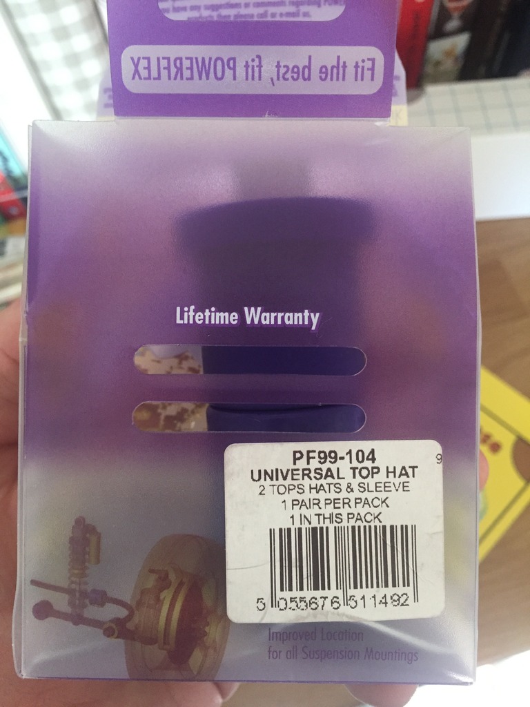
So having done a little ebay searching I've decided to make my own bushing from a generic / universal poly bushing ( about �10 on eBay) and use a cut segment of steel tube as a sleeve. I'll then use a hole saw on the remaining PPF segman and weld in place.


Possibly a mega bodge, but in absence or any other ideas it'll have to do.
Possibly a mega bodge, but in absence or any other ideas it'll have to do.
Thread Starter
Full Member
Joined: Dec 2011
Posts: 74
Likes: 0
From: England
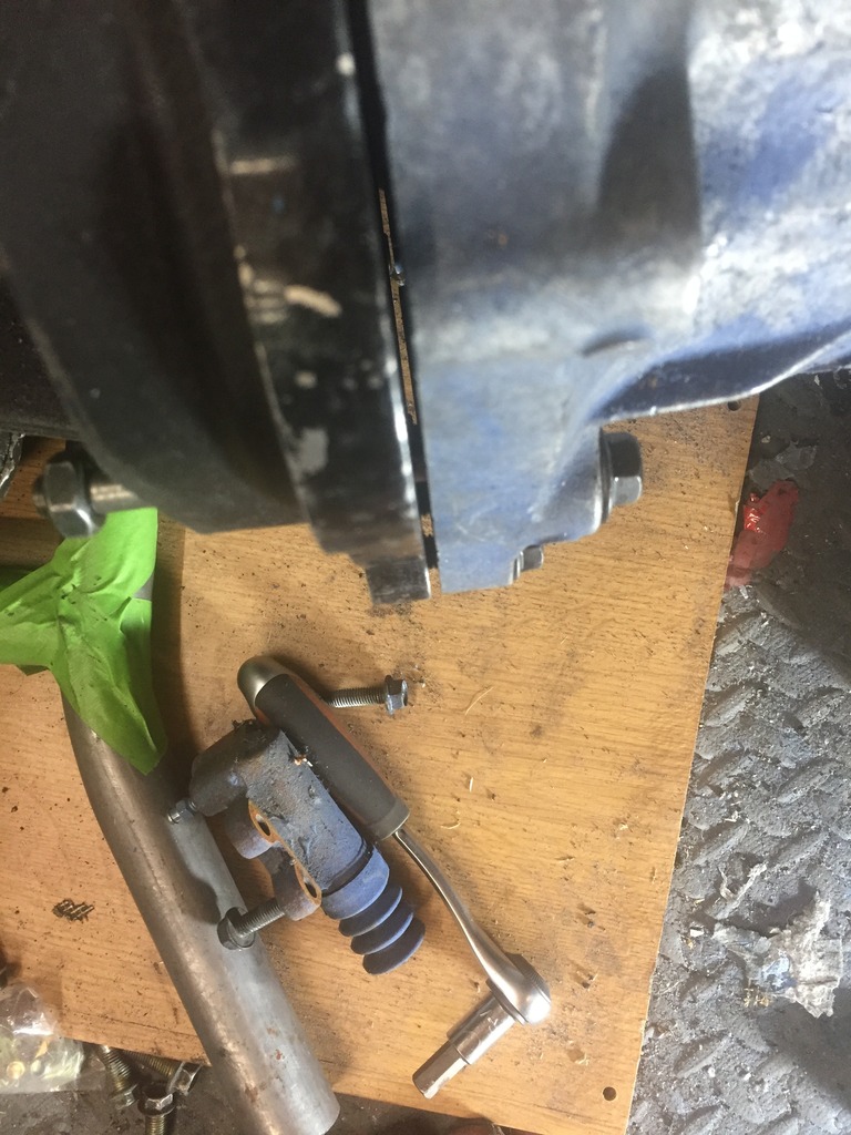
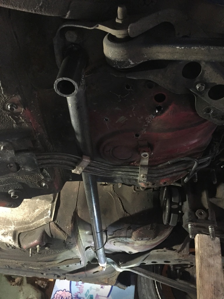
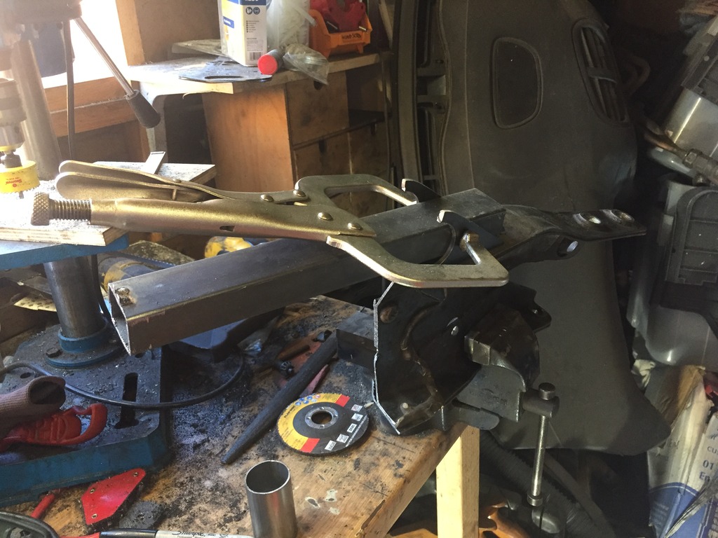
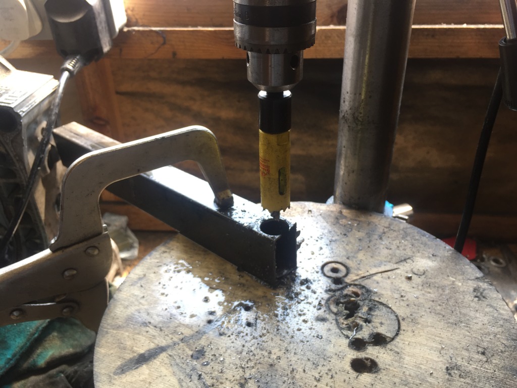
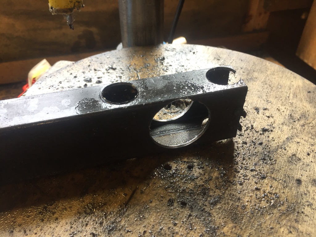
So having assembled the bits and pieces i needed for the diff mount i cracked on at the weekend with the bastardised diff mount.
So then, chop chop..
PPF Cut up:
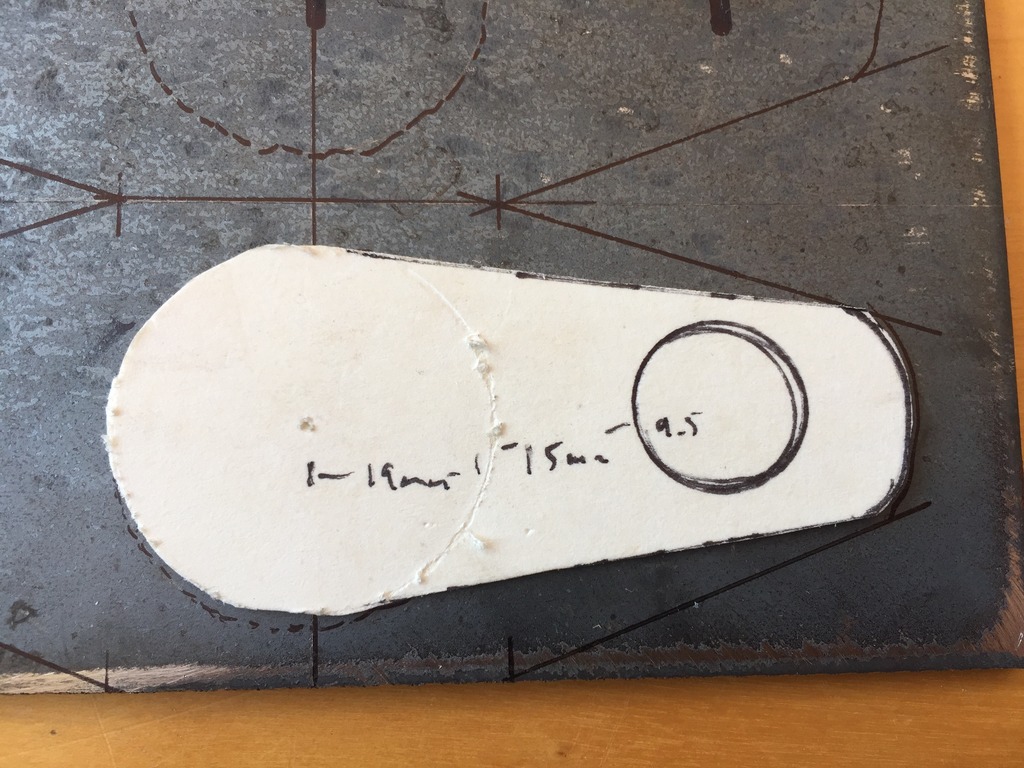
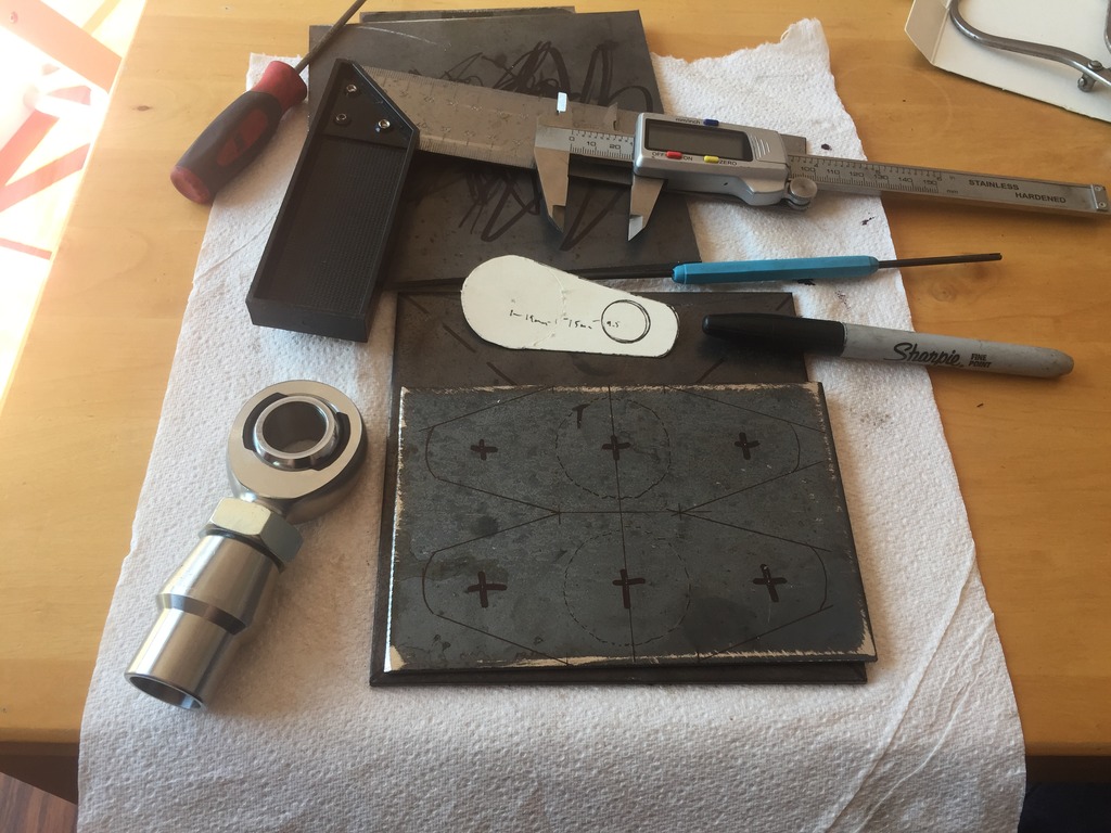
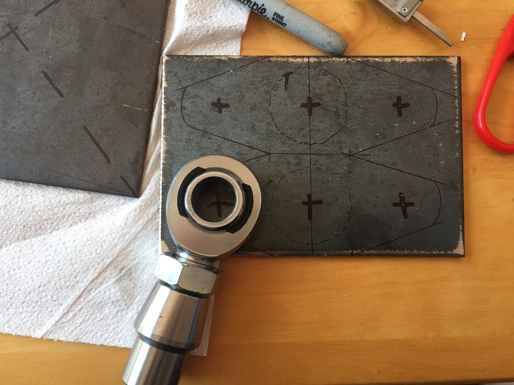
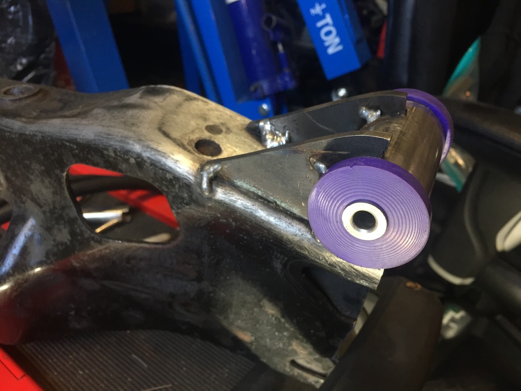
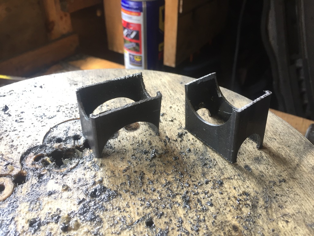
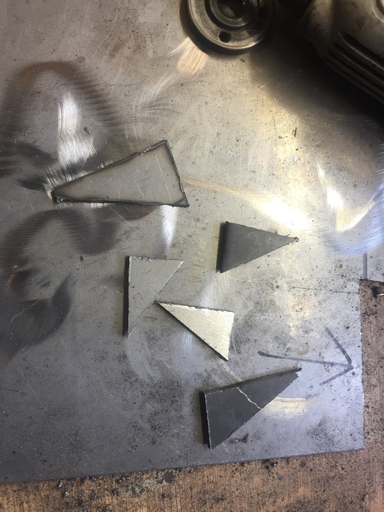
Made up some brackets for the bushing:
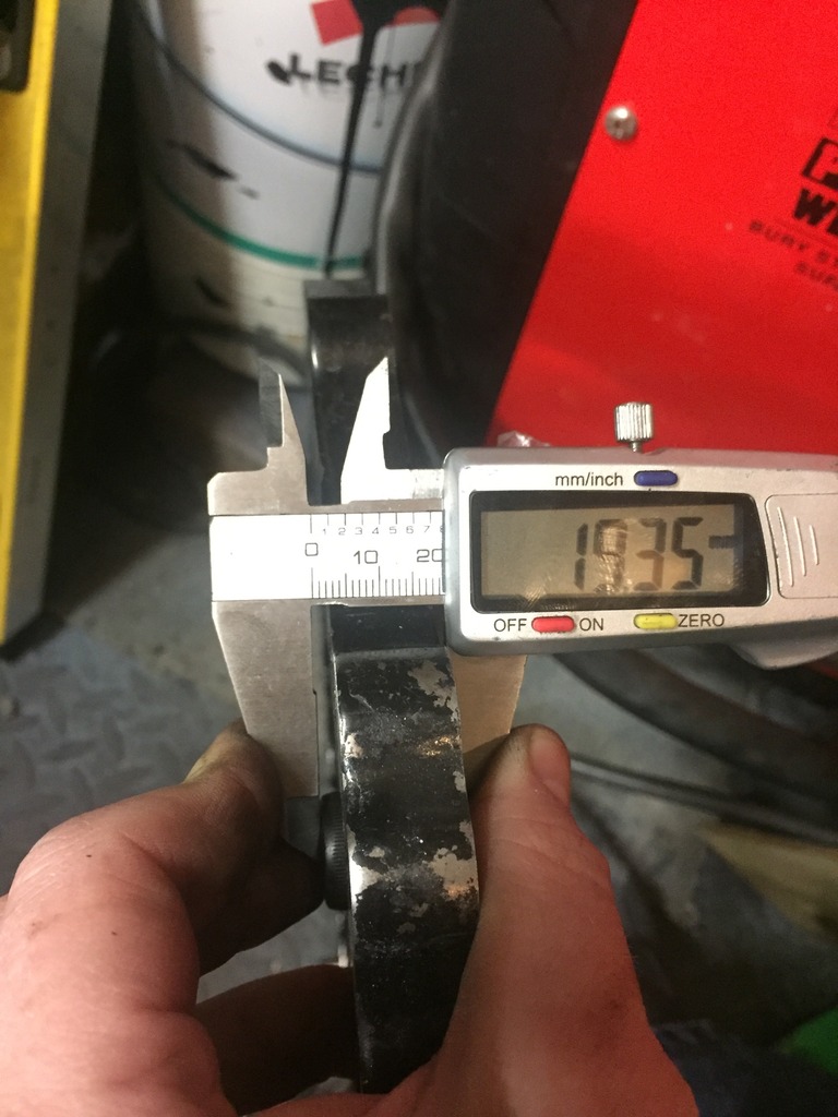
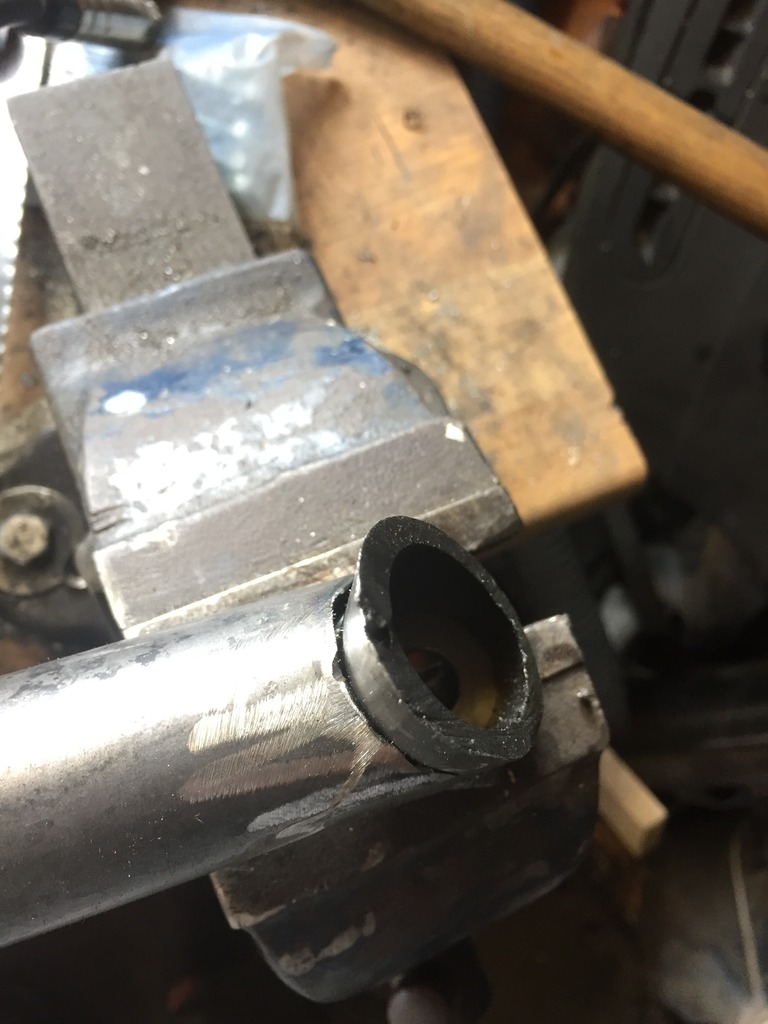
35mm ID tube cut to length and offered up to the bracket.
Also made up some brackets which will weld onto the cross member which is already on the car.
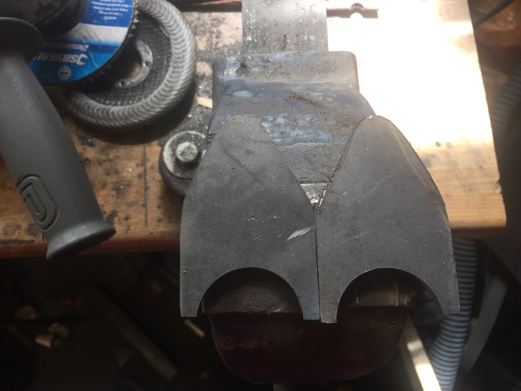
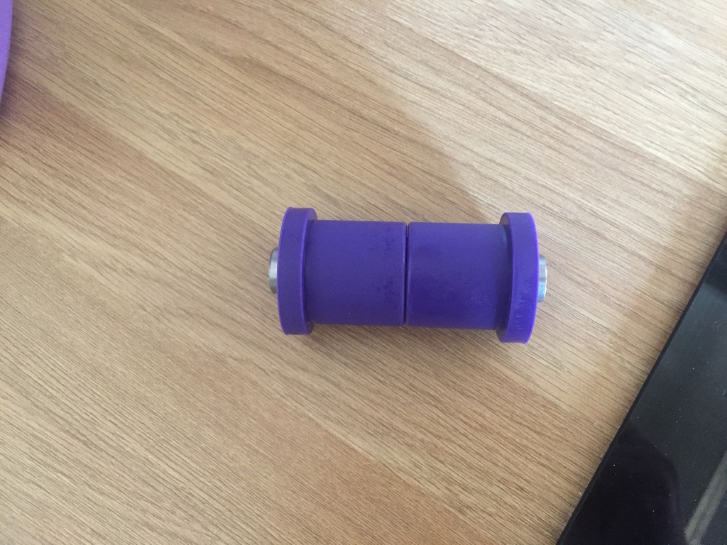
This is the power flex universal bush I'm using, as you can see it's supplied with a sleeve that's longer than the total bush length, so for my application i decided to cut it short.
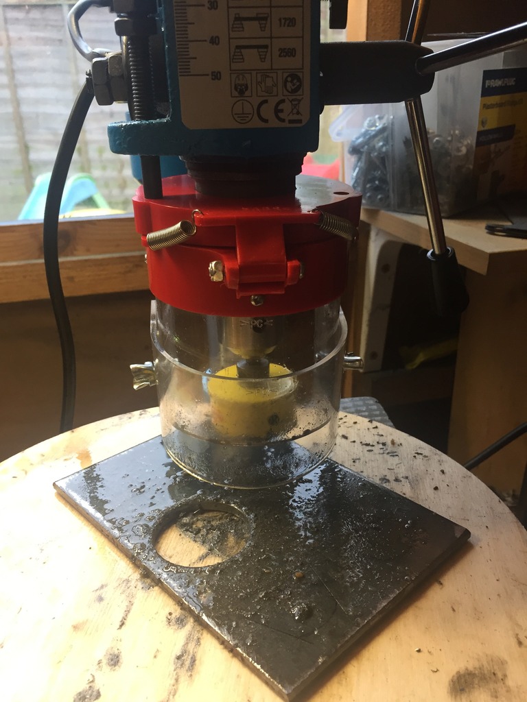
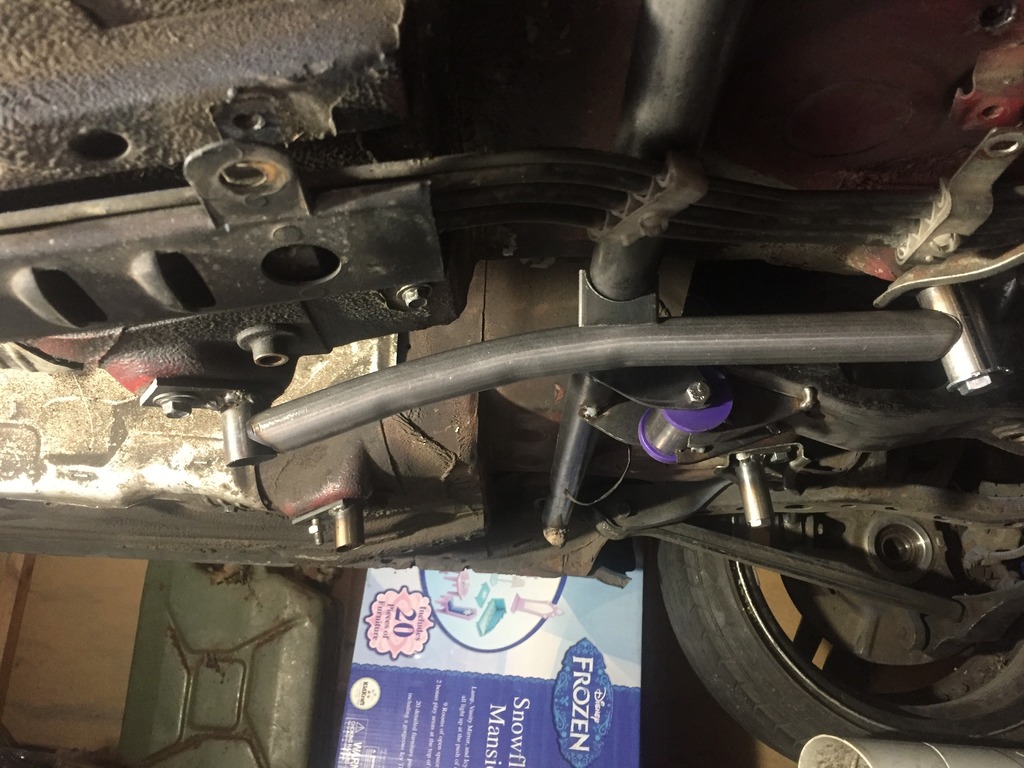
So after a bit of measuring and tinkering i spot welded the lot together:
Once bolted back onto the diff, i used my lovely new magic digital angle finder to ensure the diff face and gearbox output face were as close as possible ready for the final brackets to be tacked in place:
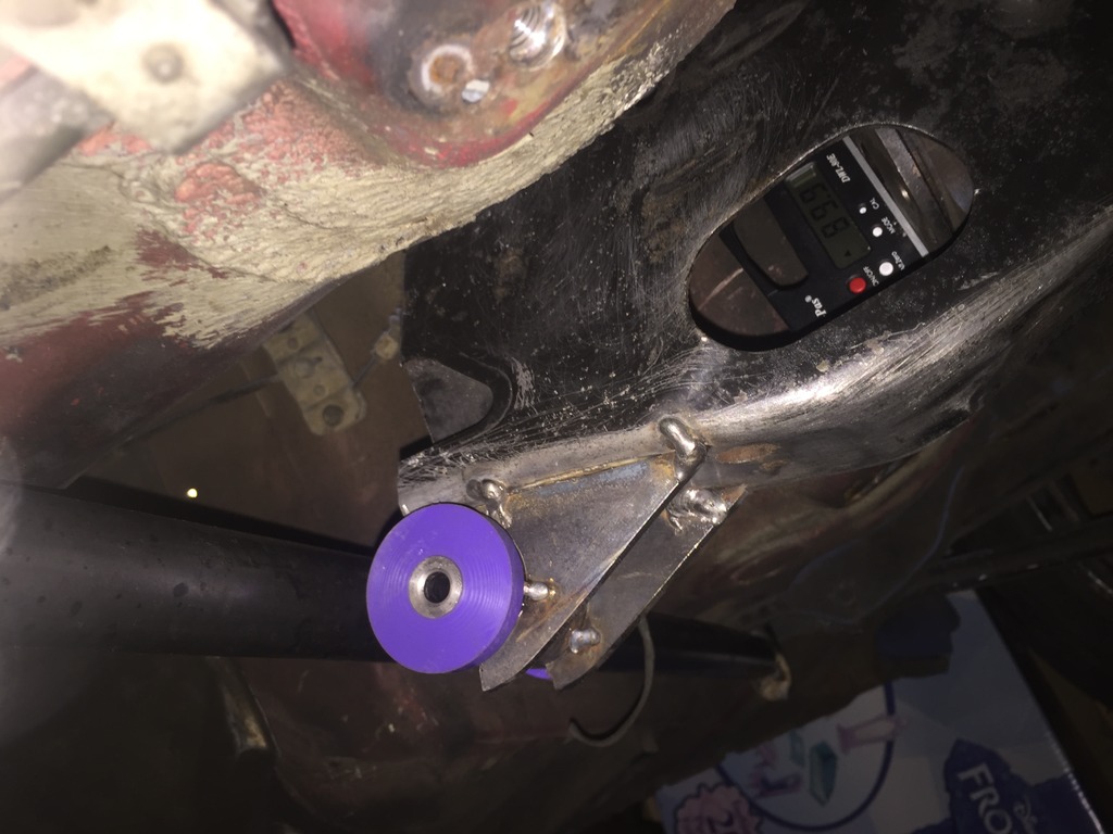
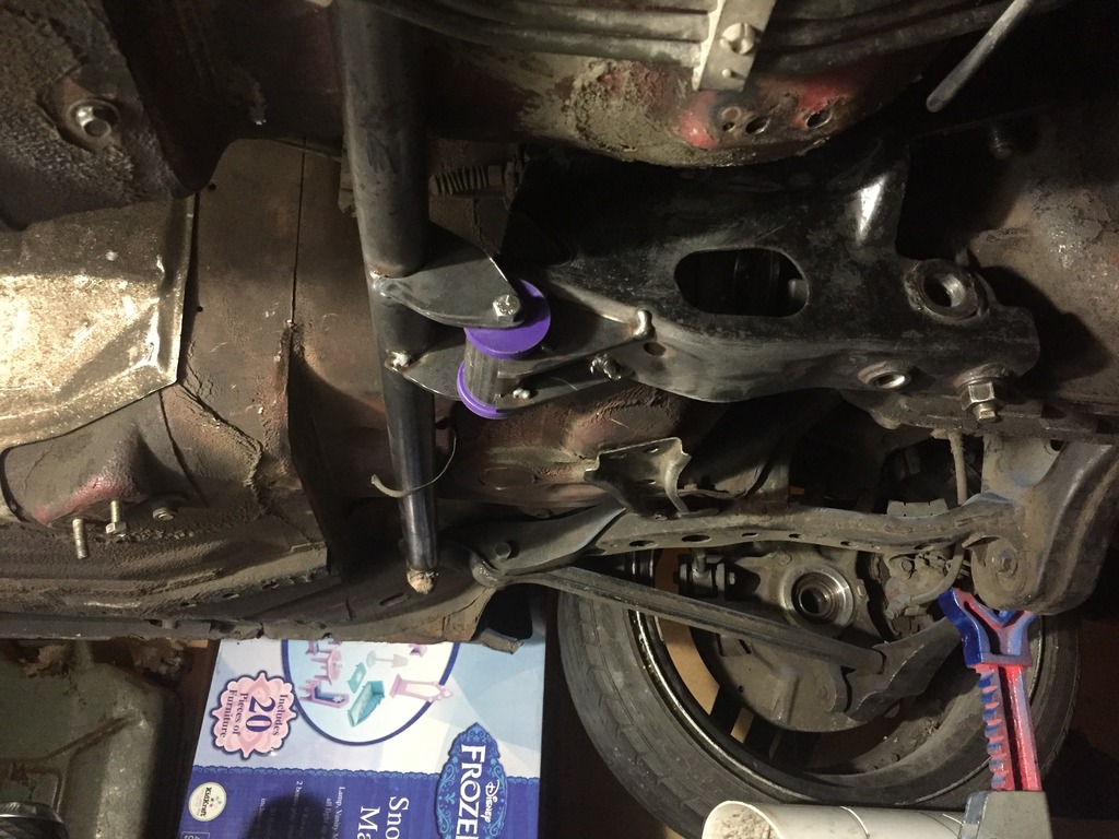
Boom... one mounted diff!
Final piece is to make the braces which attach to the cross member holes like THIS...
So then, chop chop..
PPF Cut up:
Made up some brackets for the bushing:
35mm ID tube cut to length and offered up to the bracket.
Also made up some brackets which will weld onto the cross member which is already on the car.
This is the power flex universal bush I'm using, as you can see it's supplied with a sleeve that's longer than the total bush length, so for my application i decided to cut it short.
So after a bit of measuring and tinkering i spot welded the lot together:
Once bolted back onto the diff, i used my lovely new magic digital angle finder to ensure the diff face and gearbox output face were as close as possible ready for the final brackets to be tacked in place:
Boom... one mounted diff!
Final piece is to make the braces which attach to the cross member holes like THIS...
Thread Starter
Full Member
Joined: Dec 2011
Posts: 74
Likes: 0
From: England
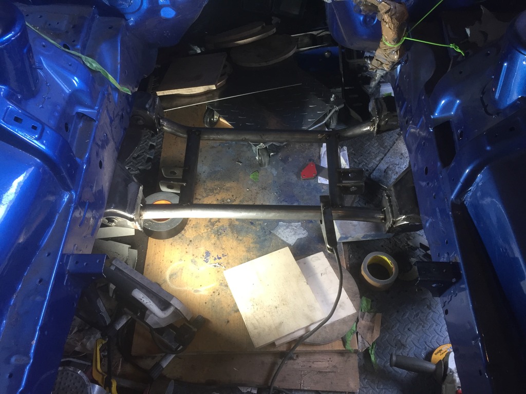
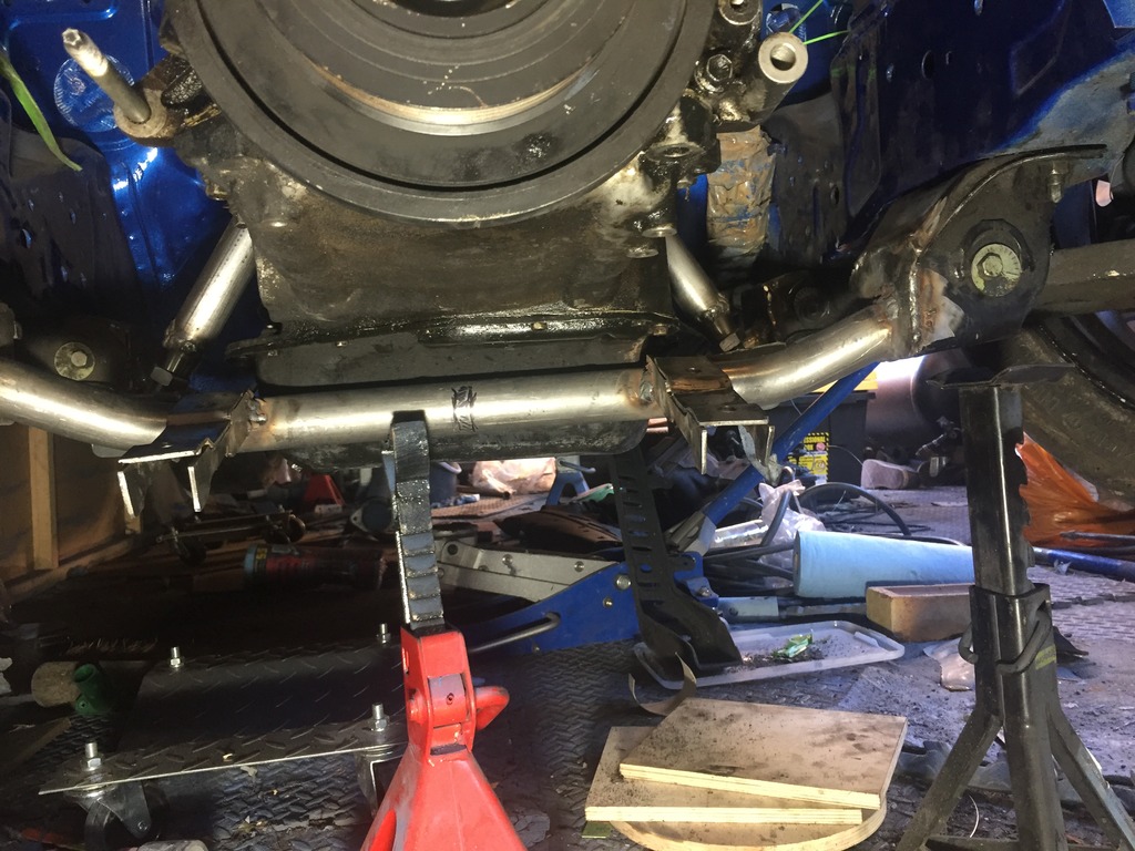
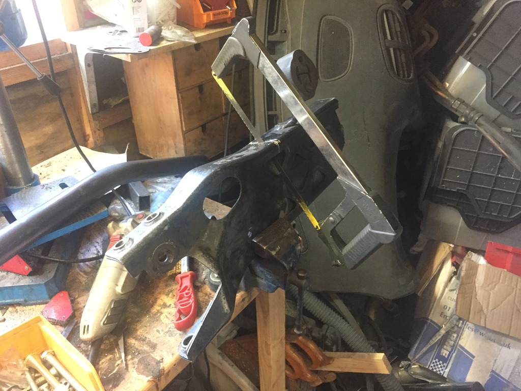
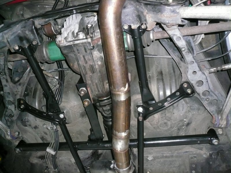
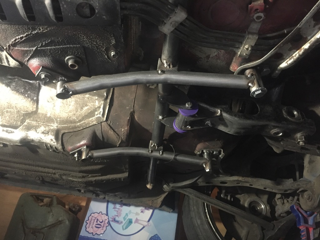
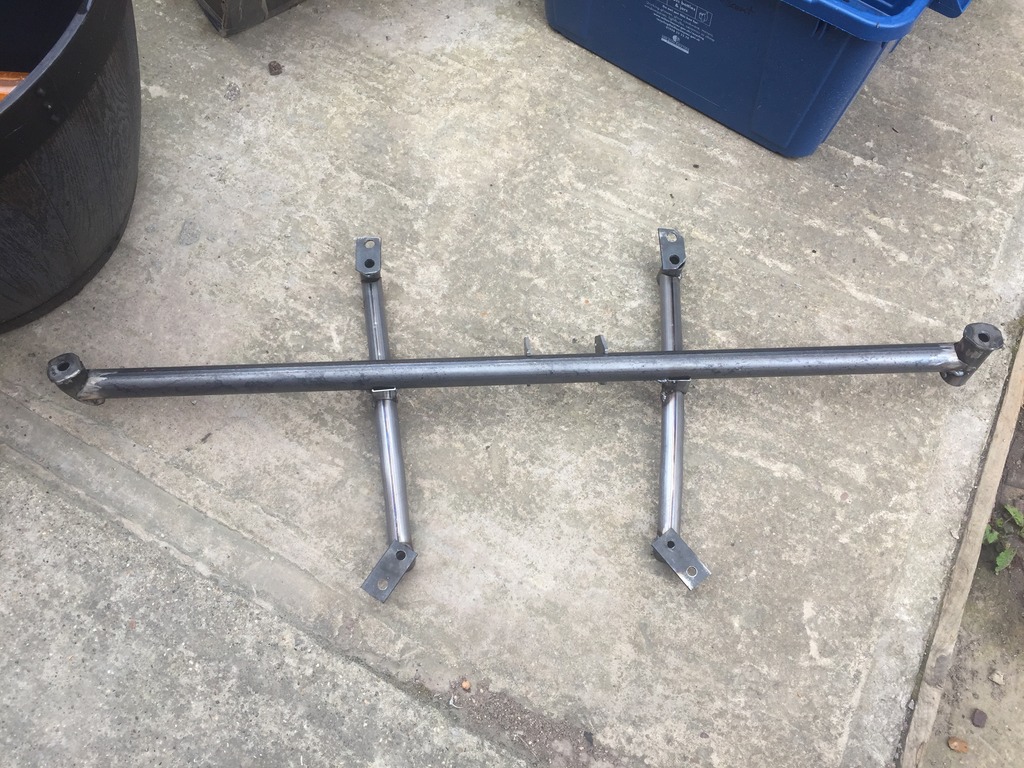
Managed to achieve a little today in terms of finishing off the diff brace support bars:
Following a suggestion i made some brackets to allow for better content between the crossed over tubing to hopefully make it that little bit more structural sound:
And then bent and notched a couple of short lengths of tube and test fitted under the car.
I think i'm getting good at this stuff
Following a suggestion i made some brackets to allow for better content between the crossed over tubing to hopefully make it that little bit more structural sound:
And then bent and notched a couple of short lengths of tube and test fitted under the car.
I think i'm getting good at this stuff
Thread Starter
Full Member
Joined: Dec 2011
Posts: 74
Likes: 0
From: England
Shame about the welding... bloody welder is doing my NUT!
Any way here it is off the car before i attempted to do a little but of triangulation before wanting to take a hammer to the wire feed :
Any way here it is off the car before i attempted to do a little but of triangulation before wanting to take a hammer to the wire feed :
Last edited by rx7ali; Jun 23, 2017 at 10:08 AM.