
Another Poor College Build, because there are never enough


haha yeah! got it figured out but wont start still. I *think* i know the answer now. I didnt set the initial timing of the motor manually like the haltech startup guide says to. Honestly I have no idea how to do this on a fd lol..

Registered User
Joined: Apr 2013
Posts: 60
Likes: 0
From: santa ana
Hey my names Nikko I work at RRR Motorsport I have one of the best haltec tunners in Cali his name is Nelson saverio if u would like u can call this number around ten o clock Monday ask for Nelson I'm sure he will solve ur problem 1714 839 8018
Yeah chance and the haltech startup say to manual set it, ill make some calls monday and see if someone cant help me out. I think I have to adjust some setting in the haltech screeb while comparing it to what I get on a timing light. Not sure though. There isnt a lot of info on sprint re and s6+ motors....
try to search for haltech PS1000 FD information. all the ignition settings/screens are the same as the sprint RE, the RE just doesnt have some of the features.
also, yeah, the crank boss/pulley is keyed, so you don't have to manually find TDC. if the engine doesn't crank over at tooth offset 10 and trigger angle 65, there is a different reason it's not starting. if you haven't messed with EMS stuff before, you need to have someone go through each setting with you.
i just contacted Chris Ludwig (an old friend of mine, and i bought the haltech from him; LMS-EFI.com. he really knows his ****) and figured out i had the two wires on each of my crank sensors swapped around, which made the overall timing about 15* too retarded. there are a lot of settings you have to have right to make these things run correctly. i've gotten maybe 7 or 8 cars running on different haltechs over the years and i'd never seen this problem...
try contacting BDC too. he is a very nice, helpful guy who you may be able to talk to on the phone and go through all your pages/settings/etc. and make sure you have everything setup correctly.
how about you just post some screenshots of your different settings into this thread?
Found this on the haltech help forums. I definitely didn't do the lock timing and then the timing light + trigger angle adjustment. I'm going to give this a shot then go from there.
Hello,
If you have an FD, your setup is just what you wrote, with the exception of the tooth offset, its set to 5 and the split goes to 15, on the FD. Also, wire up your stock ignition system the same way you would normally, and your hks unit goes after the ignition module. So, your ignition setup should be:
Spark mode: Wasted Spark
Ignition output type: Constant Charge
Output edge: Falling
Charge time: 4.5mS
To sync the ECU with the engine you must lock the timing to -5 degrees, and put the timing light on the T1 plug wire (since you only have one notch on the trigger wheel to line up the timing and its at 20* ATDC), so, with the settings as ive described, line up your timing by raising or lowering the trigger angle. When this is done, unlock your timing and tune the engine. There are plenty of base maps for most popular rotary engine combinations found HERE and HERE.
you have to have the engine running to zero the timing.
change the tooth offset to see if you can get it to fire up.
example: i entered tooth offset 10 and trigger angle 65 into my settings and it didn't work. i had to keep changing the tooth offset until i got it to fire up, and the tooth offset ended up working best at 15 (but this is only because i had the CAS wires "+" and "-" swapped, so it threw the timing off significantly)...
so just get the car to fire up (probably by changing the tooth offset around) then i can help you
make sense?
E1CFA609-2F20-43F6-8ADF-4CFDB1719C75-1679-000000FFE1F16BFA_zps5aba2e6e.mp4 Video by lotus_fd3s | Photobucket
Okay update. Got the car to start. BUUUUT, it refuses to stay on for longer then 10seconds. As soon as the key goes back to the "on" position the car dies.
Still have the following problems:
1) car dies after 10seconds after revving to 3.5k
2) relays are wired where they get powered when the key is in the "start" pos but they seem to lose power according my multimeter when in the "on" pos
3) car wont start if relays wired to have power when in "on" pos because they turn off when car is in "start"
4) tps REFUSES to read any voltage. I just put a brand new tps in and its doing the exact same thing. I checked the wires and I get 5v on the 5v power wire. The full range sensor wire reads 0.2v when disconnected but when connected reads .04v on the haltech screen.
1. do you have a wideband?
2. can you just post some pictures of how you wired this thing?
just post some details for us, man. there are several knowledgeable around here who have done multiple haltech/EMS installs in FDs...
2. can you just post some pictures of how you wired this thing?
just post some details for us, man. there are several knowledgeable around here who have done multiple haltech/EMS installs in FDs...
Yes, running a wideband. I have closed loop o2 enabled on the main settings page under inputs.
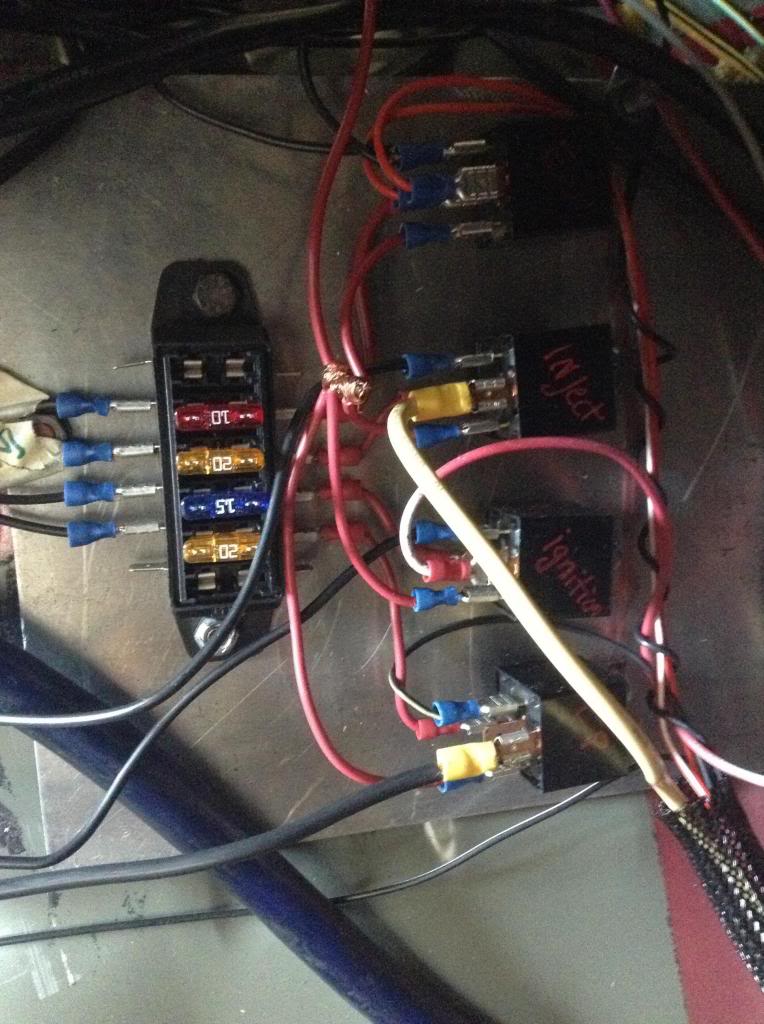
here's a pic of the relay setup. Dont mind how janky the 12v switched looks and how much of a mess it is atm. going to clean it up after i get everything sorted. Basically I'm 95% sure I'm tapping the WRONG 12v source for the signal wire. Right now I have it wired to the 10g black/blue wire coming off the ignition harness under the steering column. I have no idea what wire I'm supposed to use, and nobody on the web seems to have a straight answer.
30-batt+ ---> switch ---> fuse ----> relay
85-Ignition wire ----->split -----> relay
86-GND
87-To Accesory
87a-Not used

ok i will try to not sound like an elitist here, as i'm definitely no wiring master, but i was afraid you were going to post a picture like that.
1. if you're going to use a metal plate like that to mount all your relays/fuses, you have to protect every connection. you have about 30 connections there that are asking to blow fuses, ruin ECU drivers, and/or start a car fire. go to lowe's or home depot and buy one of the little plexiglass or lexan 1'x1' sheets and mount everything on that. and you know they have female sockets that you can PIN that plug into the terminals on those automotive relays (these cost only a few dollars). you've done a lot of work there. i'd hate to see you have a serious problem because you accidentally grounded a few wires against that metal mounting sheet.
you can't go "poor college kid" style on this type of thing or you will brick your haltech and/or start a car fire.
2. you should be getting the switched 12v you need from the original ECU plugs that came from the body, not messing with the ignition column...
the stock ECU has 4 yellow plugs that go into it; 2 are from the engine harness you removed, and 2 come in from the body to connect 12v/tacho/wheelspeed/etc. i got the following from these two plugs:
switched 12v (haltech input)
wheel speed (haltech input)
tacho (haltech output)
you can also get the constant 12v from here, but i just ran mine straight back to the battery.
3. you'll also need to separate the transmission harness from your main engine harness and hook that up most of it connects back into the white plug that is behind the blower motor near the firewall hole.
then you'll have to hookup the ground on that white plug i just mentioned so your gauges will work properly. this ground originally ran through the engine harness. so do these things and your gauges and reverse lights and speed sensor will all work correctly.
4. then you connect your constant and battery wires to the battery, connect your fuel pump power wire back to the fuel pump, connect your wideband to the haltech o2 input wire, and you're good.
now post pictures of how you connected all your sensors (particiularly the CAS plugs and the injectors, as these are the most important)
*edited for clarity
This is me:

Thanks so much for the input. Really it's helping a lot. I'd seen everyone else put them on plates which is why I used a plate. Guess I was super wrong there lol.
Can you tell me what colors those three wires are?
For 12v switched:
For Speedo:
For Tacho: (iirc its yellow/blue)
So on the white plug I separate them and do what? I just ground that one wire or am I supposed to remake the transmission harness plugs and such using my own wiring? IE, I de-loom them out of the main harness, cut up the white plug and then solder the wires to the old outputs and then out to the plugs on the transmission?
Everything else is reading properly but what I listed.
 nice pic.
i can post the wire colors for you in a couple hours, but you should have the FSM and wiring diagram, young padawan. are you attempting to install a haltech without a map? wtf?
by "separate the transmission harness" i mean: that whole section that went down to the transmission and had like 4 plugs on the end of it, the rest of your car needs those things plugged in... i mean't just remove that whole section from the main engine loom. as in, unwrap the engine engine loom, remove the transmission section from it, plug transmission section back into the car (4 plugs on the trans and that one white plug behind the heater box) then ground the ground wire
nice pic.i can post the wire colors for you in a couple hours, but you should have the FSM and wiring diagram, young padawan. are you attempting to install a haltech without a map? wtf?
by "separate the transmission harness" i mean: that whole section that went down to the transmission and had like 4 plugs on the end of it, the rest of your car needs those things plugged in... i mean't just remove that whole section from the main engine loom. as in, unwrap the engine engine loom, remove the transmission section from it, plug transmission section back into the car (4 plugs on the trans and that one white plug behind the heater box) then ground the ground wire
 I've literally never done anything like this ever so it's all new to me.
Here's the ecu pinout I'm using: According to it i should be using the 1C pin for the 12v switched is that correct?

Okay, thats what I figured. Just not sure if I have all 4 plugs or not :\ The harness the car was running on before was an auto harness jumpered to work on a manual. So I dont know if it has all of the plugs like the neutral plug or the reverse lights etc. I'll take a pick of what I have for the trans harness. I definitely have 4 plugs that look similar just not sure if pinned out right :\
pics


Last edited by Kiku; May 8, 2013 at 05:46 PM. Reason: added pics
no, you need to be using pin 1B for switched 12v.
1B for the switched 12v
1M for road speed (use a haltech DPI - digital pulsed input)
3D for cooling fan (use your haltech thermo fan wire DSI)
yellow/blue wire for tach (use haltech DPO1 - must be dpo1) and set to 35% duty 4 pulses (cant find this in the diagram at the moment, not sure which pin # it is)
1C is "the key has been turned to the START position," which may activate a "start" map inside the stock ECU or something. (this is just a guess). this pin probably gets deactivated after the key is back out of the START position, so if you use that, your haltech will just turn off after you let go of the key.
you're SOL on that automatic trans harness. i'd recommend still separating it from the engine harness and plugging it into that white plug. it is different than my MT harness though. was your car originally an automatic, or did it just have an automatic engine harness? this isnt exactly vital, but it would be nice for you to have road speed on your haltech.
Thanks for the help again! Being a life saver for me haha
I would never have figured it out on my own for that 12v.
1m would be the wire labeled "road speed sensor" i'm assuming?
I have the cooling fan wired to the the thermoswitch on the water neck.
I have the tacho wired correct then, just not set to the proper settings.
I think that's the problem I've been having with the relays. Everything is wired to the "start" position. So when the key comes back to "on" everything turns off.
I'm working on getting a replacement right now. The car came with the harness. Was always a manual but I only found out after I pulled the harness out and tried to sell it that I found out it was an auto. Going to try and get everything else working and I can always wire that all back in when I get the plugs.
Thanks for the help again! Being a life saver for me haha 
I would never have figured it out on my own for that 12v.
1m would be the wire labeled "road speed sensor" i'm assuming?
I have the cooling fan wired to the the thermoswitch on the water neck.
I have the tacho wired correct then, just not set to the proper settings.
I think that's the problem I've been having with the relays. Everything is wired to the "start" position. So when the key comes back to "on" everything turns off.
I'm working on getting a replacement right now. The car came with the harness. Was always a manual but I only found out after I pulled the harness out and tried to sell it that I found out it was an auto. Going to try and get everything else working and I can always wire that all back in when I get the plugs.
does your haltech have that road speed wire labeled? (i have a ps1000 so my harness is quite a bit different and road speed isnt separated from the other DPIs) if so, then yes.
what exactly do you mean you have the cooling fan wired to the thermoswitch on the water neck? it would be much simpler to just hook the haltech "thermo fan" wire straight to pin 3D. this pin connects straight up to the fan relays in the engine bay.
you'd just connect this wire, set the temperature in the haltech, and you're done. you can test the fan trigger wire before you hook it up to the haltech (pin 3D like i just mentioned) by simply grounding it to the chassis somewhere down there with the key ON and listen to see if the fans kick on.
Yeah I have a shielded DPI wire labeled for "road speed sensor"
There's a DPI labeled "thermofan output" which is the one I have going to the thermofan switch on the waterneck. Do i need to run another DPI to run the fans I'm assuming?
There's a DPI labeled "thermofan output" which is the one I have going to the thermofan switch on the waterneck. Do i need to run another DPI to run the fans I'm assuming?
dont confuse DPI with DPO (digital pulsed INPUT and digital pulsed OUTPUT)
all the DPIs are just inputs that you hookup to the haltech so it can read something in pulse form (like road speed pulses).
DPO can send out ground pulses to something (like a fuel injector) which is basically just a really fast switch that switches the ground on and off... or it can be a simple on/off switch (like for an e-fan relay).
so if you were to use this to trigger an e-fan (like your stock ones) all it would do is ground that wire at a certain temperature. the way you have it hooked up now won't do anything because you're just grounding your temp switch.
hook this haltech DPO thermofan wire up to the 3D pin and it will trigger your fan relay at whatever temp you set...
^like this, the haltech will see 200*F (or whatever you set the temp to), the haltech will ground that DPO thermofan wire (which goes straight to the fan relays), the fan relays will get triggered by that ground, the fans will come on.
and yes, that road speed wire would be a DPI. just peel back the insulation and shielding (make sure you dont never ground out the shielding on the signal wire when you're doing this) and hook the wire up to the road speed wire. the haltech will read this as an input so it can know what your road speed is.
you need to RTFM. you got in over your head.
it's ok though, as i say this is the best way to learn.
Ah my mistake, the thermoswitch is a dpo.
Oh okay, I think I get it. The haltech reads the water temp from the sensor, recognizes the temperature, then signals the dpo for the thermoswitch to open or close by grounding the circuit. Thus eliminating the need for the factory location thermoswitch.
Haha definitely in over my head, my friend was telling me how straight forward it is, and parts are but something's I just can't find the answers to. Over 3/4 of the time I've spent is trying to figure out how other people have everything setup or what I'm not doing right. You've been invaluable in helping me out. Usually, I can figure everything out but this has been one hell of a misadventure lol. I hate being that guy who has to keep asking questions that usually have easy answers lol thanks again!
no problem man. i just installed my ps1k last week, so it's all fresh on my mind.
post pictures of your 4 "main setup" tabs too. i think they are: main setup, fuel setup, trigger setup, and ignition setup.
if you have it all wired up correctly, any of these settings can easily keep the car from running.
post pictures of your 4 "main setup" tabs too. i think they are: main setup, fuel setup, trigger setup, and ignition setup.
if you have it all wired up correctly, any of these settings can easily keep the car from running.