
Pressure switch for A/I kit?

Pressure switch for A/I kit?
Since I am using my E8 as the injector driver I don't have a fail safe other then low fluid level. I was going to put a pressure switch into the output of the A/I pump for future fail safe.
The only thing I found was http://www.omega.com/ppt/pptsc.asp?r...500&Nav=preh03 but I really only need a pressure switch for 100psi falling.
Any ideas?
The only thing I found was http://www.omega.com/ppt/pptsc.asp?r...500&Nav=preh03 but I really only need a pressure switch for 100psi falling.
Any ideas?
doesn't the FJO ai system your using have a pressure switch controlling the pump?
you could get another one of those, and assuming its adjustable set it where you want for the fail safe.
If not how does it control pump pressure?
http://www.mcmaster.com/ search for pressure switch
edit: you need one with a no/nc (3 terminals) or you could use a relay. So if you have a switch thats set to activate at 120 the NO terminal will close at 120 while the NC will open.
coming from the other direction the opposite happens.
I'm sure you get it.
Last edited by slo; Mar 23, 2008 at 12:13 AM.
one more thing, I am quite sure the pressure switch used by my cooling mist pump to activate and deactivate (there by regulate pressure) is mcmaster part number
3460K61
it also appears to be the same device use by the cooling mist clog detector.
3460K61
it also appears to be the same device use by the cooling mist clog detector.
I just bought one from Devils own. they have 3 options...
http://www.alcohol-injection.com/wat...-switch-1.html
http://www.alcohol-injection.com/wat...-switch-1.html

Senior Member
Joined: Sep 2006
Posts: 402
Likes: 0
From: uk
FJO and Aquamist uses a completely different way to regulate line pressure. A set of internal by-pass valves (x3) inside the pump head by-pass excess pressure back to in-port when it exceeds 125psi (aquamist). Not sure what spring rating FJO uses. This is the peoper way to produce ultra smooth line pressure.
Using an on demand switch or external electrical switch to regulate pressure causes unncessary pressure spike as well as causing long term reliabilty problem to the pump motor.
Here is a warning label on every shurflo pump. One day, all PWM valve system will follow this recommendation.

Using an on demand switch or external electrical switch to regulate pressure causes unncessary pressure spike as well as causing long term reliabilty problem to the pump motor.
Here is a warning label on every shurflo pump. One day, all PWM valve system will follow this recommendation.
Banned. I got OWNED!!!
Joined: Jan 2005
Posts: 296
Likes: 0
From: Atlanta
Our switch is not the same as McMaster Carr switch. The manfucturer of ours a different company. It does appear to be nearly idenical in looks, however different manufacturers.
lastly, if anyone wants to see how smooth the flow is using an external pressure switch, here you go:
http://www.coolingmist.com/videos.aspx?videoid=15#video
The other company likes to scare anyone that does not have his kit. It will not cause any long term problems, we have been selling these for along time with no pump failures.
David
Trending Topics
Richard is quite correct in that the FJO runs something like 130psi (They mentioned something in a conversation before I bough a kit. Not sure on the number) that is internally regulated inside the pump.
Slo,
The reason why I would like a pressure switch is if the output of the pump happens to be below a certain pressure like a pump failure it will automatically send a signal to my haltech to change maps.
The kit I purchased from FJO was only the pump fittings and nozzle and driver. I didn't get the controller. I think their pressure sensor is not a switch but something they use to monitor the pressure and the controller manipulates the solenoid on its output.
Senior Member
Joined: Sep 2006
Posts: 402
Likes: 0
From: uk
Ian,
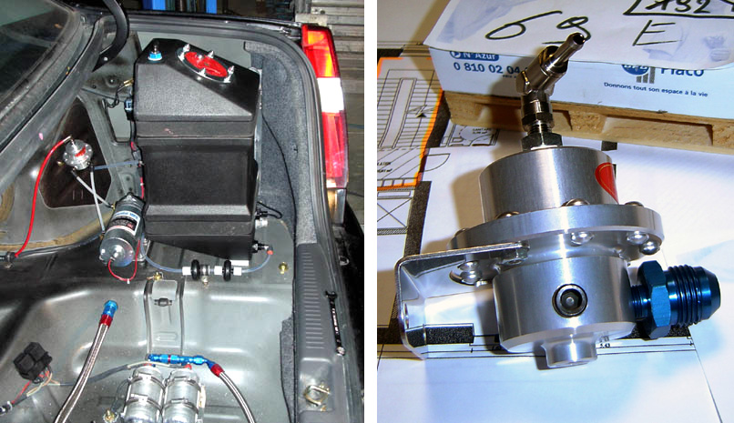
If you look carefully at the front of FJO's pump, it does not have a "on-demand" switch. It has the configured the same as the Aquamist HFS pump, using an internal by-pass.
You now have the facts and you can make you own mind up. I would suggest taking Shurflo's recommendation, on/off cycling rate faster than 2 times per seconds is not good for the pump.
A chief engineer's from Shurflo has spoken to me at length about this form of configuration. " A typing pump will draw four/five times the normal running current at startup. A typical pump can draw as much as 20-30 A peak.
If you are going for that route ensure the switch can withstand at least 20A. We don't sell pumps, I have nothing to gain from expressing my view.
Banned. I got OWNED!!!
Joined: Jan 2005
Posts: 296
Likes: 0
From: Atlanta
Further, as mentioned before, its very simple on our non s-hsv kits to eliminate pump pusing while leaving the pump switch wired factory, we are only company to have such a feature.
We will continue to dis-agree. Our kits are stress tested that includes our pumps, we dont sell our kits (WITH a LIFETIME WARRANTY) unless we are certain they will not have problems. If this pump was being used 24 hours a day non stop, I would agree with you, however the use is limited in a vehicle water injection application.
Shurflo has alot of recommenations, including not running flammable liquids, yet just about everyone does that.
David
Senior Member
Joined: Sep 2006
Posts: 402
Likes: 0
From: uk
Every Shurflo pump carries this warning, you seemed to have ignored it.
"On-demand" switch is NOT* designed to be used for regulating pressure (cyclic). It is used for shutting off the pump automatically when the pump is not in use. If it cycles more than once very 2 seconds, it is not recommended by Shurflo.
I can post up the what the Chief engineer of Shurflo said to me if you dispute my words.
Methanol usage does not threaten the life span of the pump.
If you don't see the sun rising on a misty morning, it didn't mean that didn't happen. You know you have to change to this configuration one day. The sooner the better. Except that you are so so stubborn to follow FJO's and Aquamist's foot step.
We shall see...
Last edited by Richard L; Mar 23, 2008 at 09:42 AM. Reason: * Corrected for typo
Banned. I got OWNED!!!
Joined: Jan 2005
Posts: 296
Likes: 0
From: Atlanta
Every Shurflo pump carries this warning, you seemed to have ignored it.
"On-demand" switch is designed to be used for regulating pressure (cyclic). It is used for shutting off the pump automatically when the pump is not in use. If it cycles more than once very 2 seconds, it is not recommended by Shurflo.
I can post up the what the Chief engineer of Shurflo said to me if you dispute my words.
Methanol usage does not threaten the life span of the pump.
If you don't see the sun rising on a misty morning, it didn't mean that didn't happen. You know you have to change to this configuration one day. The sooner the better. Except that you are so so stubborn to follow FJO's and Aquamist's foot step.
We shall see...
I think my intention may have been misunderstood.
I am aware that my shurflow pump is internally regulated and will always run to develope X amount of pressure. What I want to do if the pump fails monitored by a pressure switch only to send a signal to my haltech E8 to change maps. The pump will not be cycled or power interrupted in any way.
I basically have the pump wired to a switch inside the car and I will manually turn the pump when I will be into boost and I will leave it running constantly untill I no longer need the pump.
Thanks for the info. Glad to see that there is alot of knowledge towards these A/I kits and theory.
Can't wait to see what difference this will make on the car.
Ian
Senior Member
Joined: Sep 2006
Posts: 402
Likes: 0
From: uk
Ian,
You are clearly using the correct pump configured for your application. It was not clear at the beginning of the post that you are already using an internal by-pass pump.
I made the comments because I was not sure. Sorry.
You are clearly using the correct pump configured for your application. It was not clear at the beginning of the post that you are already using an internal by-pass pump.
I made the comments because I was not sure. Sorry.
The mcmaster car pressure switches would be appropriate for your safegaurd, it would be a good way to switch maps on the haltech, or even better swich the haltechs fuel trim, causing massive enrichment.
It would also be a really good way to activate your pump (or you can use the haltech to do that)
actually the best thing you can do is run a wire from the haltech's fuel pump output to one side of a relay coil, then run either a haltech output that gives ground in boost of a seprate boost switch to the other side of the coil causing the relay to switch only when the key is on and engine is running, and then only when in boost.
I think my intention may have been misunderstood.
I am aware that my shurflow pump is internally regulated and will always run to develope X amount of pressure. What I want to do if the pump fails monitored by a pressure switch only to send a signal to my haltech E8 to change maps. The pump will not be cycled or power interrupted in any way.
I basically have the pump wired to a switch inside the car and I will manually turn the pump when I will be into boost and I will leave it running constantly untill I no longer need the pump.
Thanks for the info. Glad to see that there is alot of knowledge towards these A/I kits and theory.
Can't wait to see what difference this will make on the car.
Ian
I am aware that my shurflow pump is internally regulated and will always run to develope X amount of pressure. What I want to do if the pump fails monitored by a pressure switch only to send a signal to my haltech E8 to change maps. The pump will not be cycled or power interrupted in any way.
I basically have the pump wired to a switch inside the car and I will manually turn the pump when I will be into boost and I will leave it running constantly untill I no longer need the pump.
Thanks for the info. Glad to see that there is alot of knowledge towards these A/I kits and theory.
Can't wait to see what difference this will make on the car.
Ian
How does this bypass you speak of work?
diaphragm pumps like all of these shurflow pumps rely on a pressure differential right.
If your bypassing pressure back to the intake of the pump, wouldn't that cause the pumps intake pressure to climb continuously in low demand?
I know about the RRFP, infact the right RRFP alone is a really good manually controlled injection system.
People have been doing this on bike and cars for years, combine a variable rate RRFP with an adjustable rate with a properly sized injection nozzle and a diaphragm valve. Activate the diaphragm valve and pump at the same time and adjust the RRFP to get the right output and rise rate and they you have a perfectly modulary variable injection system that goes from say 40 PSI to 150 PSI (some RRFP's can rise 10 psi per pound of boost on their max adjustment)
FJO and Aquamist uses a completely different way to regulate line pressure. A set of internal by-pass valves (x3) inside the pump head by-pass excess pressure back to in-port when it exceeds 125psi (aquamist). Not sure what spring rating FJO uses. This is the peoper way to produce ultra smooth line pressure.
Using an on demand switch or external electrical switch to regulate pressure causes unncessary pressure spike as well as causing long term reliabilty problem to the pump motor.
Here is a warning label on every shurflo pump. One day, all PWM valve system will follow this recommendation.
Using an on demand switch or external electrical switch to regulate pressure causes unncessary pressure spike as well as causing long term reliabilty problem to the pump motor.
Here is a warning label on every shurflo pump. One day, all PWM valve system will follow this recommendation.
Senior Member
Joined: Sep 2006
Posts: 402
Likes: 0
From: uk
Obviously the overall bypass valve's openings will allow enough fluid to be cycled within the two side of the diaphragm.
The pump is not suppose to run continuously as the fuel injection system. You just need to turn on the pump just before you start pulsing your PWM valve.
I know about the RRFP, infact the right RRFP alone is a really good manually controlled injection system.
People have been doing this on bike and cars for years, combine a variable rate RRFP with an adjustable rate with a properly sized injection nozzle and a diaphragm valve. Activate the diaphragm valve and pump at the same time and adjust the RRFP to get the right output and rise rate and they you have a perfectly modulary variable injection system that goes from say 40 PSI to 150 PSI (some RRFP's can rise 10 psi per pound of boost on their max adjustment)
People have been doing this on bike and cars for years, combine a variable rate RRFP with an adjustable rate with a properly sized injection nozzle and a diaphragm valve. Activate the diaphragm valve and pump at the same time and adjust the RRFP to get the right output and rise rate and they you have a perfectly modulary variable injection system that goes from say 40 PSI to 150 PSI (some RRFP's can rise 10 psi per pound of boost on their max adjustment)
What type of pump are you using on your PWM valve delivery system?
Senior Member
Joined: Sep 2006
Posts: 402
Likes: 0
From: uk
The mcmaster car pressure switches would be appropriate for your safegaurd, it would be a good way to switch maps on the haltech, or even better swich the haltechs fuel trim, causing massive enrichment.
It would also be a really good way to activate your pump (or you can use the haltech to do that)
actually the best thing you can do is run a wire from the haltech's fuel pump output to one side of a relay coil, then run either a haltech output that gives ground in boost of a seprate boost switch to the other side of the coil causing the relay to switch only when the key is on and engine is running, and then only when in boost.
It would also be a really good way to activate your pump (or you can use the haltech to do that)
actually the best thing you can do is run a wire from the haltech's fuel pump output to one side of a relay coil, then run either a haltech output that gives ground in boost of a seprate boost switch to the other side of the coil causing the relay to switch only when the key is on and engine is running, and then only when in boost.
Can you explain how a pressure a switch be used as a fail safe?
If his bypass is working then pressure should stay constant and not go below 125 (or whatever) so set the switch at 120. Give the switch continuity with the pump's ground on its common wire (if controlling the pump via ground, or + if controlling the pump via a pos signal).
Now you have a switch with an actuation window of on at 120 and above the other end of the window doesn't matter so much as long as its lower end isn't too extreme.
When the system is running as it should the switches NC port will be continuously open.
If using a + to feed the switch common you will now need to invert the signal with a relay.
connect either the inverted signal or the switch NC to a haltech digital input and configure it to switch maps, for both fuel ign and boost if doing closed loop boost control.
Have more conservative maps with extra fuel and less timing.
So here's what happens, pressure drops below the lower limit of the open window (call it 110), NC which is open because the switch is activated closes, boost gets limited to whatever the wastgate spring is set at, and both the fuel and ign maps become conservative.
You can wire this in about 4 different ways, since you can invert any haltech input.
This doesn't help you in the event of a clog, or failed (failed closed) HSV but does cover you in case of running out of alcohol, a massive leak in the system or a mechanical or electrical failure of the pump.
I think a failed open HSV would be pretty apparent and not so catostrophic.
I can't picture how it would work without a dedicated return line.
Any of the sureflow pumps are capable of producing a great deal more volume than would be injected by most people, it just seems like the pressure on the input side of the diaphragm would build until there was almost no pressure differential.
I'm not calling you a liar by any means, I'm just having trouble picturing it.
In a FPR bypass you are bypassing fuel back to the tank, for a OPR bypass you are bypassing fuel back to the sump. Never directly to the pump intake port.
I am using cooling mist HSV and PUMP, have been using it with varying mixtures up to 100% methanol.
I am happy with the quality and functionality of the components.
PWM ing the pump with the pressure switch is no different than PWM ing with a controller, except that the freq and pulse width would be continuously variable. At its max flow with the freq at its highest it would still be a fairly low freq.
If the pump doesn't have a problem PWM from a controller then I would say I can't see it being a problem from a switch.
Also the pressure fluctuations as seen on a gauge where small like a 5 PSI sweep at the highest.
The valve work more or less on the same principle as an oil pump's pressure relief valve. Imagine you punch a hole in the diaphragm, you will not make pressure at all.
Obviously the overall bypass valve's openings will allow enough fluid to be cycled within the two side of the diaphragm.
The pump is not suppose to run continuously as the fuel injection system. You just need to turn on the pump just before you start pulsing your PWM valve.
I am more focused on the 1:1 FPR. RRFP regulator can be anything between 1:1 to 4:1. RSR makes good WAI for motorbikes based on the RRFPR.
What type of pump are you using on your PWM valve delivery system?
Senior Member
Joined: Sep 2006
Posts: 402
Likes: 0
From: uk
I can't picture how it would work without a dedicated return line.
Any of the sureflow pumps are capable of producing a great deal more volume than would be injected by most people, it just seems like the pressure on the input side of the diaphragm would build until there was almost no pressure differential.
I'm not calling you a liar by any means, I'm just having trouble picturing it.
Instead of thinking by-passing the fluid into the input port, think of it as a pump with a broken diaghragm.
I don't think I can explain this any simplier.
We have been using a biggest shurflo pump since 2006 with three internal by-pass valves. The pump kept to 125psi at all times. Believe me, this is the way Shurflo has been recommended if you want a constant water pressure.
In a FPR bypass you are bypassing fuel back to the tank, for a OPR bypass you are bypassing fuel back to the sump. Never directly to the pump intake port.
I am using cooling mist HSV and PUMP, have been using it with varying mixtures up to 100% methanol.
I am happy with the quality and functionality of the components.
I am using cooling mist HSV and PUMP, have been using it with varying mixtures up to 100% methanol.
I am happy with the quality and functionality of the components.
If you are happy with your setup and works for you, there is no reason to look further.
PWM ing the pump with the pressure switch is no different than PWM ing with a controller, except that the freq and pulse width would be continuously variable. At its max flow with the freq at its highest it would still be a fairly low freq.
If the pump doesn't have a problem PWM from a controller then I would say I can't see it being a problem from a switch.
Also the pressure fluctuations as seen on a gauge where small like a 5 PSI sweep at the highest.
If the pump doesn't have a problem PWM from a controller then I would say I can't see it being a problem from a switch.
Also the pressure fluctuations as seen on a gauge where small like a 5 PSI sweep at the highest.
- PWM via a mechanical switch yields very high currents due to low frequency start/stop cycle. At low frequency, 10 to 30 pulses /sec. The inductance of the motor winding will not play a smoothing role on cushioning the peak current build up in the motor winding.
- PWM via an electronic switch is often set to a frequency between 400KHz to 2KHz. With this frequency matched to the inductance of the motor windings, you will get ultra-smooth motor speed control.
With the best intention in the world, you can view some of the videos on the following link when a there is a frequency mis-match..
http://forums.evolutionm.net/showthr...=295728&page=3
You can do an experiment, put your pump on the bench, unbolted. Now test the two configurations. You will find the PWM (mechanical) driven pump will not stay on the bench for long. Temperature will read higher on the after the same period of operation.
Take another reading from an undamped pressure gauge, you wil find the pressure ripple is much higher than 5psi.
You are pretty well committed to your current "coolingmist/low frequency" set up but you can open up you mind a little to other ways of controlling pressure without going against Shurflo's recommendation.
Wow. I looked at some of those threads and saw this video.
http://s240.photobucket.com/albums/f...5tunevideo.flv
Not much spray. I posted on another thread asking what the spray patterns should look like since I cannot comment on any other spray patterns since I've never seen an A/I kit working before. At least out of the car.
My nozzle sprays more of a mist. I wonder in this video if the pressure is too low or they are trying to control mist at the bottom end of the range.
Joined: Feb 2006
Posts: 2,897
Likes: 2
From: Renton/Bellevue/Seattle WA
Wow. I looked at some of those threads and saw this video.
http://s240.photobucket.com/albums/f...5tunevideo.flv
Not much spray. I posted on another thread asking what the spray patterns should look like since I cannot comment on any other spray patterns since I've never seen an A/I kit working before. At least out of the car.
My nozzle sprays more of a mist. I wonder in this video if the pressure is too low or they are trying to control mist at the bottom end of the range.
http://s240.photobucket.com/albums/f...5tunevideo.flv
Not much spray. I posted on another thread asking what the spray patterns should look like since I cannot comment on any other spray patterns since I've never seen an A/I kit working before. At least out of the car.
My nozzle sprays more of a mist. I wonder in this video if the pressure is too low or they are trying to control mist at the bottom end of the range.
It looks as though there is a 3inchish tube over the spray nozzle. The mist is hitting the sides of the skinny tube and collecting causing the solidish water fall. I don't really know who told you to look at that, but that has nothing to do with anything, as you do not know any about its setup. (there are no details on the pump, pump pressure, volts to the pump (although it looks like 5 volts?), nozzle size, ect...
This is what it should look like. http://youtube.com/watch?v=-8G2aPexZZ4
This is what it should look like. http://youtube.com/watch?v=-8G2aPexZZ4