
AEM water injection install write up


AEM water injection install write up
If you've decided to go with the AEM water/alcohol injection kit then this thread will give some tips on a 3rd gen install. I attached pictures in order of their relevance. My goal for the install was to go as stock stealth as possible. I used the wiper washer reservoir and tried to mount everything else completely out of sight. The stock tank holds just over a 1/2 gallon. To put it in perspective an M1 nozzle at full pumping capacity would take 15 minutes to empty the tank. That is at full boost. The medium M3 nozzle will last for 6.25 minutes. The system has a progressive pump so it is only pumping at the max while the car is at full boost. Depending on how you drive and this will be more than enough for most people. I won't cover everything in the AEM install instructions but I will try to cover the stuff that I wish I had known and that is specific to the 3rd gen. You can order the kit without the AEM reservoir. I just pulled the float and pickup from the included tank.
For starters you'll need to jack up the front end and remove the following pieces, and interior and exterior panels to gain access
-battery and battery box
-driver side footwell left foot panel (small thin flat tip screwdriver to extract the pins and pop the panel retainer buttons)
-drivers side door scuffplate. You can pop it up using your fingers.
-deadpedal footrest (10mm socket)
-driver side front wheel, wheel well trim. You'll need a #1 or so phillips and a butter knife to removed the plastic retainers that keep the trim in place. The trim is a little tricky to get out. Just be patient, there are quite a few plastic screw retainers that you really have to look for.
-plastic panel below oil cooler on both sides. 10mm and #1 phillips and knife)
-panel under radiator. 10mm
Washer tank/float/pickup:
You'll now have access to remove the washer tank but....while it's still mounted pay careful attention to where you'll be drilling for the float and pickup. I had to do this twice and buy a used washer tank off a forum member because I made a mistake on the float and drilled the hole about 1/4" too low. You have to install the float at the highest possible point that will still allow the "float" portion of the float to pivot and reach the low point that will trigger the controller to give you the low signal. There are many fitment issues on the stock tank. For the float I could only find one place that would work. When the tank is out there is a triangular bump out on the side of the tank the faces the front bumper. This will allow the back of the float to protrude through the triangular hole and not hit anything. You'll need a 9/16" bit for the pickup and 3/4" bit for the float. I used a "uni-bit" which can make it much easier once you've drilled a pilot hole. There are more options for the pickup but make sure the pickup is not in the way of the floats travel. Also the AEM pickup protrudes over a 1/2" into the tank even after installed. This could allow the pump to suck dry even if the float has not triggered yet. I chose to grind it down until there was only about 3/16 of thread left which is much more than the thickness of the plastic anyways. If you're careful when you screw it in the threads will tap the plastic just fine. I chose to use "threebond" sealant on both penetrations so I didn't have to worry about leaks.
Pump:
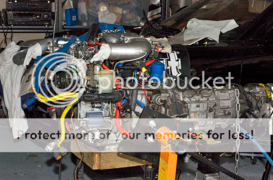
I mounted the pump high on the tow hook plate on the passenger side with the pump end on the top. There is a nice open area if you don't have dual oil coolers. The kit comes with various nuts, bolts and self tapping screws. The bottom two holes are fairly easy to drill and install. The top two I had to do blindly. You can remove the pump from the mounting plate and just work with the plate to mark and drill your holes. Makes sure you drill the hole for the self taps slightly smaller than the screw so it has some metal to bite into. It is a good idea to thread in the self taps before you install the pump, it will make it easier when you can't see what you're doing. Once you're done you can mount the pump with nuts/bolts on the bottom holes and then carefully install the self tapping screw at the top without being able to see them. The reason for the self taps on top is that the screw go into an area you will not have access to so you can't use nuts/bolts. Be sure and use washers on the fasterner heads because they will pull right through the rubber feet on the pump.
Injector:
You will need a 1/8" NPT 27 (threads per inch) tap and 11/32" bit. The location of the injector is definitely open for debate. My car is stock and will remain at stock boost levels. Do your research and read threads in the auxlilary injector forum about injector size and location. Some will tell you to inject pre-turbo. I wanted to keep it simple and supplement the stock intercooler and get the cleaning that water injection provides. You will get lots of ideas and opinions but it all comes down to what your goals are. When you do decide where to tap, just be careful to not tap too much so you have a nice tight fit on the injector threads. The plastic pipe is fairly thick but just take your time. I ran the tap 4 or 5 times cutting a little deeper until I was satisfied with how well the injector threaded in to the point where it bottoms out and allows the nylon washer to seal. I also used a little teflon tap just in case.
Controller/LED: I mounted the controller under the dash using heavy duty velcro. This allows you to pull it down to access to the test button, error LED, and the potentiometer screws to adjust the boost triggers. The location I chose was the left side a/c return, it's above and slightly to the right of the hood latch cable. I mounted the LED in the center of a tri-power dash gauge pod. The LED flashes to indicate the pump speed and if there are any errors or low fluid signal.
Wiring: In the wheelwell there is a rubber cap that you have to remove and punch a hole through the insulation to get access into the interior. If you have run gauges before you may have already done this. You can route all wires, and vac line through here. Slice an "x" in the rubber cap and reinstall it before you pull wires. Make sure the slices are big enough to fit a bunch of wires and tube about the diameter of a candy cane. The rubber will stretch some. I used 1/8" nylon boost tube as a fish tape. Once you've pulled them from the interior into the wheelwell you can wrap them and strap them as high and possible. If you don't you will have trouble getting the wheelwell plastic trim back in place. You can then route the wires to the float, pump and battery. Buy some split loom wire insulation and wrap everything so you don't end up having a short on a metal edge.
Water tubing/Vac line:
You can "tee" your boost vacuum tube and run the included vac line into the interior along with your wires. It simply needs to connect to the controller. Run the water tubing so it won't kink and use care so it is not going to rub. There are plenty of different ways to run the wires and tubes so just do what seems best and protects the wire/tubes.
Tips:
- Extend the wires on the float before you install. They are only like 4" long and will be difficult to splice once installed on the tank.
- Yellow controller wire should be plugged into the upper right female terminal on the fuse box. This will turn on the controller any time you turn on the key. You can also use a switch inline with the yellow wire if you want to be able to run the car without the injection system.
- You don't have to connect the controller or LED directly to the battery. Run a 12 or 14 gauge wire to the interior and just connect the controller and LED there rather than running the dinky 20 ga.and 22 ga. wires to the engine compartment.
If you have any questions please feel free to ask.
For starters you'll need to jack up the front end and remove the following pieces, and interior and exterior panels to gain access
-battery and battery box
-driver side footwell left foot panel (small thin flat tip screwdriver to extract the pins and pop the panel retainer buttons)
-drivers side door scuffplate. You can pop it up using your fingers.
-deadpedal footrest (10mm socket)
-driver side front wheel, wheel well trim. You'll need a #1 or so phillips and a butter knife to removed the plastic retainers that keep the trim in place. The trim is a little tricky to get out. Just be patient, there are quite a few plastic screw retainers that you really have to look for.
-plastic panel below oil cooler on both sides. 10mm and #1 phillips and knife)
-panel under radiator. 10mm
Washer tank/float/pickup:
You'll now have access to remove the washer tank but....while it's still mounted pay careful attention to where you'll be drilling for the float and pickup. I had to do this twice and buy a used washer tank off a forum member because I made a mistake on the float and drilled the hole about 1/4" too low. You have to install the float at the highest possible point that will still allow the "float" portion of the float to pivot and reach the low point that will trigger the controller to give you the low signal. There are many fitment issues on the stock tank. For the float I could only find one place that would work. When the tank is out there is a triangular bump out on the side of the tank the faces the front bumper. This will allow the back of the float to protrude through the triangular hole and not hit anything. You'll need a 9/16" bit for the pickup and 3/4" bit for the float. I used a "uni-bit" which can make it much easier once you've drilled a pilot hole. There are more options for the pickup but make sure the pickup is not in the way of the floats travel. Also the AEM pickup protrudes over a 1/2" into the tank even after installed. This could allow the pump to suck dry even if the float has not triggered yet. I chose to grind it down until there was only about 3/16 of thread left which is much more than the thickness of the plastic anyways. If you're careful when you screw it in the threads will tap the plastic just fine. I chose to use "threebond" sealant on both penetrations so I didn't have to worry about leaks.
Pump:
I mounted the pump high on the tow hook plate on the passenger side with the pump end on the top. There is a nice open area if you don't have dual oil coolers. The kit comes with various nuts, bolts and self tapping screws. The bottom two holes are fairly easy to drill and install. The top two I had to do blindly. You can remove the pump from the mounting plate and just work with the plate to mark and drill your holes. Makes sure you drill the hole for the self taps slightly smaller than the screw so it has some metal to bite into. It is a good idea to thread in the self taps before you install the pump, it will make it easier when you can't see what you're doing. Once you're done you can mount the pump with nuts/bolts on the bottom holes and then carefully install the self tapping screw at the top without being able to see them. The reason for the self taps on top is that the screw go into an area you will not have access to so you can't use nuts/bolts. Be sure and use washers on the fasterner heads because they will pull right through the rubber feet on the pump.
Injector:
You will need a 1/8" NPT 27 (threads per inch) tap and 11/32" bit. The location of the injector is definitely open for debate. My car is stock and will remain at stock boost levels. Do your research and read threads in the auxlilary injector forum about injector size and location. Some will tell you to inject pre-turbo. I wanted to keep it simple and supplement the stock intercooler and get the cleaning that water injection provides. You will get lots of ideas and opinions but it all comes down to what your goals are. When you do decide where to tap, just be careful to not tap too much so you have a nice tight fit on the injector threads. The plastic pipe is fairly thick but just take your time. I ran the tap 4 or 5 times cutting a little deeper until I was satisfied with how well the injector threaded in to the point where it bottoms out and allows the nylon washer to seal. I also used a little teflon tap just in case.
Controller/LED: I mounted the controller under the dash using heavy duty velcro. This allows you to pull it down to access to the test button, error LED, and the potentiometer screws to adjust the boost triggers. The location I chose was the left side a/c return, it's above and slightly to the right of the hood latch cable. I mounted the LED in the center of a tri-power dash gauge pod. The LED flashes to indicate the pump speed and if there are any errors or low fluid signal.
Wiring: In the wheelwell there is a rubber cap that you have to remove and punch a hole through the insulation to get access into the interior. If you have run gauges before you may have already done this. You can route all wires, and vac line through here. Slice an "x" in the rubber cap and reinstall it before you pull wires. Make sure the slices are big enough to fit a bunch of wires and tube about the diameter of a candy cane. The rubber will stretch some. I used 1/8" nylon boost tube as a fish tape. Once you've pulled them from the interior into the wheelwell you can wrap them and strap them as high and possible. If you don't you will have trouble getting the wheelwell plastic trim back in place. You can then route the wires to the float, pump and battery. Buy some split loom wire insulation and wrap everything so you don't end up having a short on a metal edge.
Water tubing/Vac line:
You can "tee" your boost vacuum tube and run the included vac line into the interior along with your wires. It simply needs to connect to the controller. Run the water tubing so it won't kink and use care so it is not going to rub. There are plenty of different ways to run the wires and tubes so just do what seems best and protects the wire/tubes.
Tips:
- Extend the wires on the float before you install. They are only like 4" long and will be difficult to splice once installed on the tank.
- Yellow controller wire should be plugged into the upper right female terminal on the fuse box. This will turn on the controller any time you turn on the key. You can also use a switch inline with the yellow wire if you want to be able to run the car without the injection system.
- You don't have to connect the controller or LED directly to the battery. Run a 12 or 14 gauge wire to the interior and just connect the controller and LED there rather than running the dinky 20 ga.and 22 ga. wires to the engine compartment.
If you have any questions please feel free to ask.


Trending Topics
No, I really would like to be able to post a difference in the IAT, exhaust temps or AFR but honestly I just don't need all that information with my car other than to have data for this install. Somebody with a pfc will do this and hopefully can give us all some before and after readings.

Joined: Oct 2001
Posts: 6,279
Likes: 728
From: Florence, Alabama
thanks on behalf of the board for your helpful thread. i would like to also post it in the AI section...
as to IAT and EGT and AFR... water does not materially change them. water works primarily within the combustion chamber to greatly lower the heat while cleaning the rotors etc.
re nozzle sizing....
M1 flows 1 gallon per hour (GPH) or 63 CC/Min
M3 flows 3 GPH or 189 CC/Min
Mazda has us running around 10% rich so the excess gas can cool the CCP.
10% rich adds 84 BTUs of cooling
189 CC/Min of water adds 403 BTUs of cooling
many people run around 300 CCs which is the M5 nozzle
hc
Last edited by Howard Coleman; Jan 22, 2010 at 09:13 AM.
What a coincidence where you put the water injector.
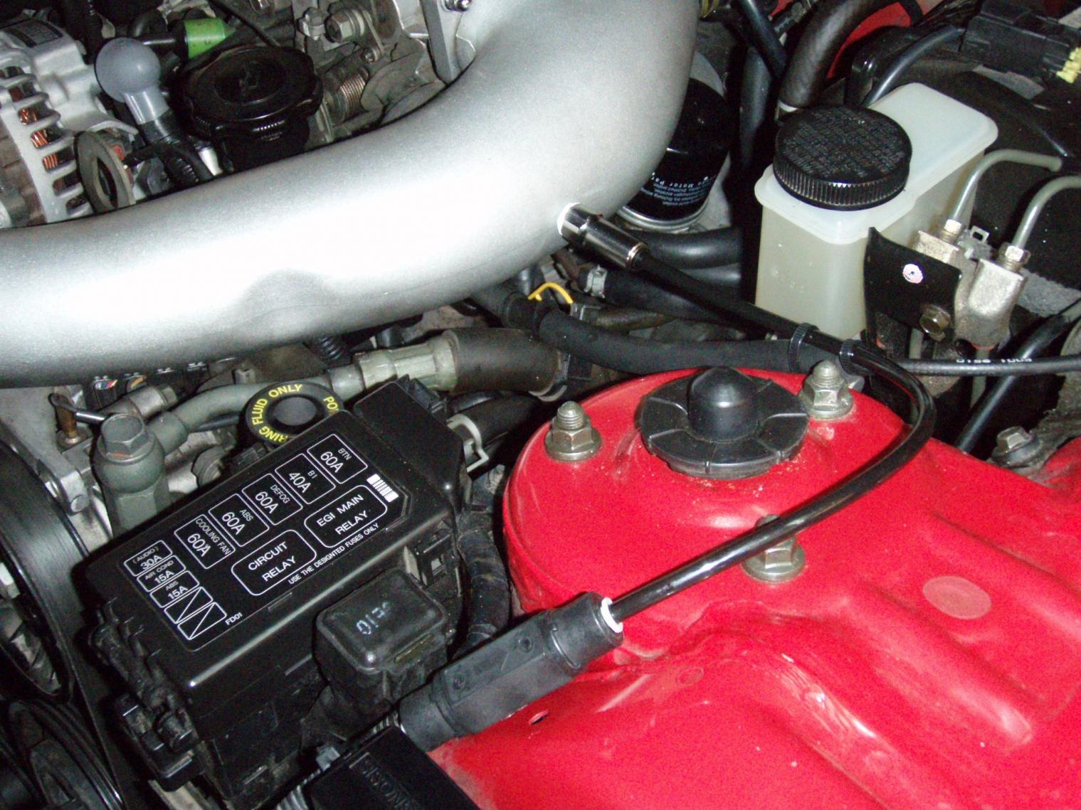
I was going to mount it pre-turbo but saw instances in the Subaru forum of the compressor blades being damaged with water spray pre-turbo.
I was going to mount it pre-turbo but saw instances in the Subaru forum of the compressor blades being damaged with water spray pre-turbo.
thanks on behalf of the board for your helpful thread. i would like to also post it in the AI section...
as to IAT and EGT and AFR... water does not materially change them. water works primarily within the combustion chamber to greatly lower the heat while cleaning the rotors etc.
re nozzle sizing....
M1 flows 1 gallon per hour (GPH) or 63 CC/Min
M3 flows 3 GPH or 189 CC/Min
Mazda has us running around 10% rich so the excess gas can cool the CCP.
10% rich adds 84 BTUs of cooling
189 CC/Min of water adds 403 BTUs of cooling
many people run around 300 CCs which is the M5 nozzle
hc
as to IAT and EGT and AFR... water does not materially change them. water works primarily within the combustion chamber to greatly lower the heat while cleaning the rotors etc.
re nozzle sizing....
M1 flows 1 gallon per hour (GPH) or 63 CC/Min
M3 flows 3 GPH or 189 CC/Min
Mazda has us running around 10% rich so the excess gas can cool the CCP.
10% rich adds 84 BTUs of cooling
189 CC/Min of water adds 403 BTUs of cooling
many people run around 300 CCs which is the M5 nozzle
hc
I started out using the 130cc/min nozzle which is the smallest the AEM system came with.
Tonight I installed the 315cc/min nozzle, which I guess is an M5. The car ran perfectly. I thought is was an M3 so I expected it to run fine but it looks like a stock engine, stock tune, stock ignition can handle M5 quantity just fine.
I used the same line that is coming from the intake manifold for the boost gauge. If you do not have a boost gauge you can run a line from the same nipple that Mazda put on the manifold. It works perfectly even though it is on the same line as the boost gauge. One of the pictures should show the "tee" where is sits under the dead pedal, that line runs up to my boost gauge. If you have any more questions, feel free to ask.
Adam
Adam
I never tested it with the spray nozzle, I just tested it with the water tube to get the system primed and confirm the pump was working. I can't say for certain but I don't think there is a problem with a little drip after the pump shuts off. The air velocity will move the water drips into the engine and they'll pass through. As long as it stops dripping after a second or two I think that would be normal.
The car definitely has a little more power and I don't think I am having an issue with hot outside temps. I'm in TX and the air temp is usually above 70 and sometimes 100. I will have a better idea this summer.

I have not made any changes to the stock ECU with either the water injection, HKS downpipe, and K&N stock location air filter. Totally stock tuning. My understanding is that unless you are adding an amount of alcohol that will actually effect your air/fuel ratio than you don't need to re-map.
I do not have a Power FC, IAT gauge or exhaust temp gauge so I can only say how I think it has helped. I have stock 16" wheels and VR dunlops, in 2nd gear the back end breaks loose, not from dropping the clutch, but when I give it gas. Boost is 10-8-10 perfectly on my VDO gauge. Maybe all the stock RX-7s had that much power in 2nd gear but I don't remember it from before the install.
I do not have a Power FC, IAT gauge or exhaust temp gauge so I can only say how I think it has helped. I have stock 16" wheels and VR dunlops, in 2nd gear the back end breaks loose, not from dropping the clutch, but when I give it gas. Boost is 10-8-10 perfectly on my VDO gauge. Maybe all the stock RX-7s had that much power in 2nd gear but I don't remember it from before the install.
Even with a PFC, simple, boost activated systems like the OP's are frequently installed for safety and longevity...not just performance. For that you wouldn't tune with AI. You tune and then add AI for the additional margin.