Adaptronic Temperature correction with Modular ECU?
#1
Temperature correction with Modular ECU?
What are you guys running for temp correction?
The ECU has the ability to use correction factors for Air Temp vs Fuel, Air Temp vs Ignition, and Coolant Temp vs Ignition
Unfortunately, the base map has all 3 of them at zero
I would expect these values to be reasonably consistent between engines, assuming the same sensor and sensor placement. Anybody have some good values they would like to share?
#2
I've attached my current map
I just started tuning it, so it's quite rough.
My boost solenoid duty control is set to 0%, as I'm just starting out and would like to be limited to 7psi.
I've got stock twins/engine, ID2000 secondaries, aftermarket/rewired fuel pump, fuel/oil pressure sensors, intake/IC/exhaust, MAC solenoids for boost control, and an Innovate WB.
I'm also running an AEM CD-7 digital dash in place of the stock dash.
Air pump is gone.
Possibly some things I'm forgetting.
I've copied over the ignition settings from my old PFC tune, along with the ignition temp corrections.
I don't know how I would complete the charge temp correction graph in the Fuel Tuning area
Also no idea how to set up the Knock control/sensing portion
#3
Using the default values in the heatsoak percentage map is working quite well for me. My AFRs are within +- .5 from cold start to totally heat soaked. I tested a few different strategies but couldn't find any improvements.
I have not personally found a need to remove any timing with increased IAT as my timing map is fairly conservative, but your setup may differ.
I have not personally found a need to remove any timing with increased IAT as my timing map is fairly conservative, but your setup may differ.

#7
Banned. I got OWNED!!!
Enrichment via coolant temperature and air temperature are incredibly important... Oh well, did anyone consult the instruction manual? 


Trending Topics
#10
Banned. I got OWNED!!!
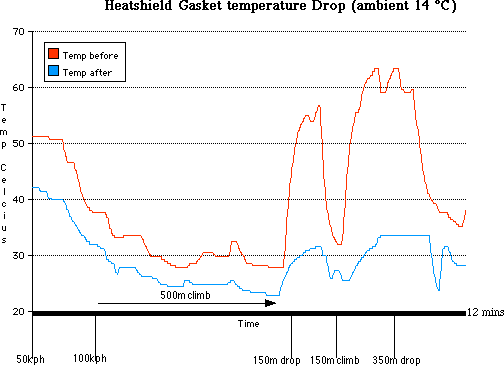
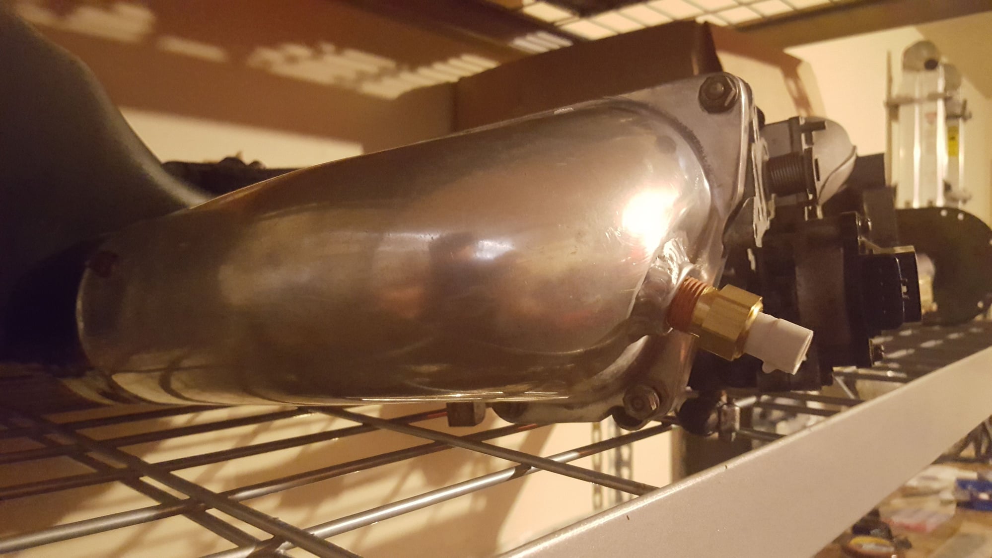
x2 This is a big deal in the Honda world where the IAT sensor is located on the center of the intake manifold runner which gets substantially heatsoak. The more accurate way was threading and sealing the sensor in the sealed airbox. Dramatically improved drivability as I could now see real IAT, not some heatsoaked skewed figure.
The following users liked this post:
Tim Benton (12-28-18)
#13
Banned. I got OWNED!!!


I really wish someone made a set of these for the rotary community. I might end up doing it myself... ugh. This between the Engine/IM and IM/TB would be enough to make that elbow really accurate.
The following users liked this post:
Tim Benton (12-28-18)
#14
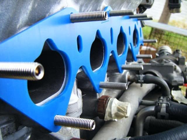
I thought someone made those a while back...when I mean a while, like 2005ish since I have a set of white LIM and UIM spacers. Never installed since I got them after I purchased and installed a street ported engine.
that is what the blue spacers are in the picture above correct, or something similar?
that is what the blue spacers are in the picture above correct, or something similar?
#15
Adaptronic use a blend of coolant and intake air temperature to create an estimated charge temperature value. It assumes that the intake temperature is actually closer to the coolant temperature at idle because the air is moving very slowly. It works quite well without moving the sensor. I believe that this idea was first developed by Ford? Autronic use the same method. You can change the bias towards coolant temperature using a 2D table
#16
Banned. I got OWNED!!!
I thought someone made those a while back...when I mean a while, like 2005ish since I have a set of white LIM and UIM spacers. Never installed since I got them after I purchased and installed a street ported engine.
that is what the blue spacers are in the picture above correct, or something similar?
that is what the blue spacers are in the picture above correct, or something similar?
I believe I'll pass this onto one of my buddies who's all about this (and the plastics/material science) behind it to hopefully come up with a better solution. I'd say minimum thickness of 5mm and possibly the use of steel throughout to help aid in strength/durability.
Thread
Thread Starter
Forum
Replies
Last Post
Adaptronic Indroduction to the new Modular ECU's!
Turblown
Adaptronic Engine Mgmt - AUS
6
12-10-16 05:33 PM
Turblown
Adaptronic Engine Mgmt - AUS
3
11-07-16 01:18 PM
metalCORE
Adaptronic Engine Mgmt - AUS
1
10-10-16 09:30 PM


