Adaptronic PLX integration
#1
Registered User
Thread Starter
PLX integration
Cross posted from here
Hi all,
There are 3 methods to use the PLX gauge interface.
1) As a display only (no wideband O2 input, or O2 input via analogue input).
2) With a PLX wideband O2 sensor
3) With an Innovate wideband O2 sensor, TC4 4xEGT probe input, or both
In each of these cases, you will need the PLX interface board. I'll add this to the online store very soon.
1) The PLX interface board needs +12V and GND on the connector on the left. You should connect this to the ECU +12V and power ground.
2) The interface board has a 4-pin square molex connector (bottom right in this picture) which will provide power for a gauge. If you want to run multiple gauges, you can connect them in parallel to this connector. This connector provides +3.3V and +8V for the gauge. The gauge might come with a separate voltage regulator with a 12V input, 8V output and ground, and it will say in the documentation that you need to cut a wire and connect this regulator in instead. Don't do this, just plug it into our board. I did it this way to make it easy for people.
3) The interface board also has a 3.5mm headphone socket, marked "PLX output" in this picture. The gauge needs to plug into here. If required you can use multiple gauges using the double adaptors that PLX provide with the gauge.
4) The interface board has a 2.5mm headphone socket on the bottom left in this picture. It has to connect to the "serial in" port on the Select ECU using a straight-through 2.5mm cable. You can buy them through a dealer for Innovate motorports; they have a very short (6") cable (part number 3789) as well as one that's about 3 ft long (part number 3760).
5) This is where it varies depending on your wideband connection:
a) If you're using a PLX wideband sensor, connect the output of the "sensor module" (the one marked "TX") into the 3.5mm port marked "PLX input" on the board. This ONLY works with a single PLX wideband sensor; it won't work with two sensors or a wideband and an EGT. Make sure that the "Term" jumper is populated on the "sensor module" (it comes this way when purchased from PLX). You don't need the "Analog" output of the sensor module or the RX, just the TX, O2 sensor and power. Select the option "PLX out / in" in the software under Serial "in" port under Special Functions.
b) If you're using an Innovate wideband sensor / TC4 EGT amplifier / other Innovate chain, connect the output of the Innovate ("Serial out") into the Innovate input on the PLX interface board. If you are using an LC-1, it comes with a cable - and you must plug the terminator into the "Serial In" on the LC-1. If you purchased an MTX-L (with the gauge) from Adaptronic, then we include the cable to go from the 4-pin "serial out" of the MTX-L to the 2.5mm serial in on the PLX interface board. If you purchased the MTXL directly or through another Innovate dealer, you will need the Innovate cable part number 3812. Select the option "PLX Out / Innovate in" in the software under Serial "in" port under Special Functions.
If you're using just a TC4, then connect the serial out of the TC4 into the PLX interface board input and use the same software setting.
If you're using a TC4 and a wideband (LC-1 or MTX-L), then the output of the LC-1 / MTX-L must connect into the "serial in" on the TC4, then the output of the TC4 has to connect into the input on the PLX interface board.
c) If you aren't using a serial wideband, just select "PLX Out / Innovate in" in the software.
Known issues:
1) There doesn't appear to be a way to show that a sensor has no valid reading other than to stop transmitting that channel. So if you don't have EGT probes, they appear as zero (°C, which displays as 32°F - the protocol is all in metric but the default display is in imperial for some reason).
2) There doesn't appear to be a way to switch between vacuum / boost automatically; I don't know why but everyone seems to refer to manifold gauge pressure as inHg in vacuum, and psi in boost. The gauge doesn't support this from what I can tell; it has 3 separate channels for vacuum, boost and MAP. So we just implemented MAP. The default MAP unit is inHg, which is not a format that would be familiar to anyone as far as I know (absolute pressures seem to always be represented in kPa) so to have the number being meaningful you need to change the display unit to kPa.
3) I haven't found out yet how to make the gauge store the unit selection; I've changed it to metric units and then power cycled the gauge and it comes back in imperial. I've asked PLX about this.
4) The duty cycle is only on the 1st injector channel, which for non-staged injection engines will be correct. However for some reason although it displays on the LEDs around the outside of the gauge and appears on the rolling graph / stripline / chart recorder - the number always shows 0.01. I've also asked PLX about this; I think it's a bug in their firmware.
As before, we recommend using the Innovate wideband input rather than the PLX input, because the PLX doesn't give you fault conditions such as the sensor is cold, heater open circuit and so on - it just gives you an incorrect lambda reading. If you're only using it for a gauge (which is probably how PLX intended it originally) this is fine - or if you're running your ECU open loop then this is also fine, but if you want to run closed loop then the ECU needs to know when it can use the sensor reading and when it has to be ignored, and as far as I know Innovate is the only one that does this.
I'll post a proper video once I've shot it.
Here's where to get the software / firmware from
I'll send some of the interface boards over in the next box to Turbosource and put the interface boards up on the website as well.
#4
Registered User
Thread Starter
I'm still working out the price of the interface boards, they do cost a bit to make when you include the cable to go to the ECU and so on (plus the assembly setup /stencil cost etc). I'm not really interested in making money off them (I want to sell ECUs) but at this stage it looks like it will be more than half the cost of the DM6. I'd like it to be less, and it would be if the gauges had their own internal supplies and used RS232. So I might post the schematic of the interface board here so if anyone doesn't want to buy one they can make their own... Thoughts?
#5
I'd make a few and post an honest price. You need to make something. It's only fair for your time and effort.
And if you want to post the schematic, do that too. Heck you could do that too.
You have a theme of giving options. Why not here too. That way you are saying "here is the information for free, but a service costs this much"
And if you want to post the schematic, do that too. Heck you could do that too.
You have a theme of giving options. Why not here too. That way you are saying "here is the information for free, but a service costs this much"
#7
Registered User
Thread Starter
Finally did a video to show the PLX gauges here:
Also I've uploaded the schematic / parts list / PCB design on the forum here for anyone that wants to make their own.
PLX setup
Yes, I will be updating the ECU firmware to show boost/vac instead of MAP, doesn't change the interface board. Cheers!
Also I've uploaded the schematic / parts list / PCB design on the forum here for anyone that wants to make their own.
PLX setup
Yes, I will be updating the ECU firmware to show boost/vac instead of MAP, doesn't change the interface board. Cheers!
Trending Topics
#8
Registered User
Thread Starter
Hi guys,
The DM100 can be used.
The 3.5mm cable has to go to the "sensor RX" port on the DM100 control box.
Then you can just use the up arrow from the main screen where it says "view OBD2 data" to go the various displays like RPM, engine temp etc. You'll probably need to go and choose which gauges you want to display using either the menu or the PC application.
But I can verify it does work!
Thanks
Andy
#10
Registered User
Thread Starter
Hi James, so long as it has the PLX sensor input then it should be OK. I didn't use the OBD function on the DM100, just the sensor input port.
Hopefully this week I can ship them; that's sorted out with the connectors now, but I want to ship with some more ECUs otherwise the shipping for just the PLX boards is really expensive!
Cheers
Hopefully this week I can ship them; that's sorted out with the connectors now, but I want to ship with some more ECUs otherwise the shipping for just the PLX boards is really expensive!
Cheers
#14
Registered User
Thread Starter
The DM-100 box does provide power to the gauge, but the box does not talk RS232 (normal standard serial) - it still talks 3.3V serial so you still need a level shifter to convert the two.
You could just use the part of the circuit I supplied above for the serial converter and ditch the power supply section - the only problem is that circuit needs 3.3V to operate so you'd need to get that from somewhere...
Thanks
Andy
#18
This is such an awesome integration!!
PLX Integration
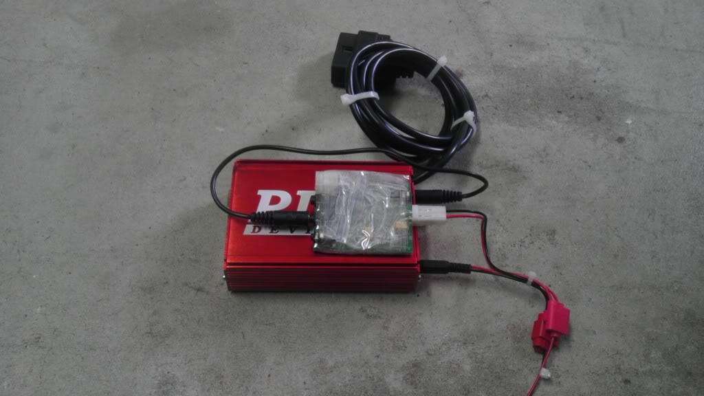
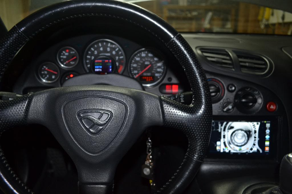
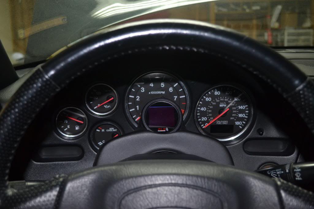
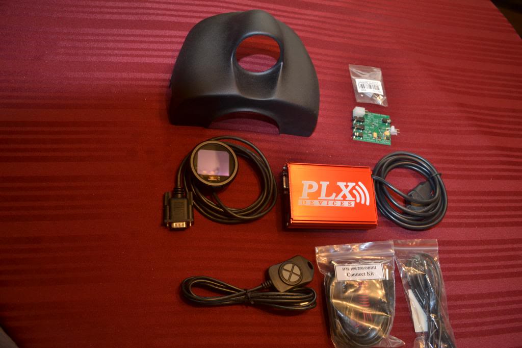
I got the gauge, pod, and integration board installed and rocking. I LOVE IT! The DM100 allows me to edit so much. Colors, backgrounds, and pretty much any useable metric the ECU sees. As the ECU pulls my EGTs, and AFRs from the Innovative products, it slaps it up for me to view. Very pleased with it. The Adaptronic integration board is pretty raw. With no actual case, I gave it a good wrap with packing tape. This allowed me to mount it to the PLX module, and run my serial data cables to the ECU. I admit, the ECU pocked is getting REALLY busy, but its all solid.


 [/QUOTE]
#19
Looks good XLR8!
Would you or anyone who has this installed mind throwing the ECU sensed voltage onto your PLX for a day? Mine is dancing all around from 13.1 to 14 once the car is warm. I'm thinking that I have a bad diode in my alternator. It's either that or the ECU is sampling so fast that it's picking up the rectified AC waveform from the alternator.
Just curious what everyone else sees.
thanks!
#21
Be good to know how yours operates ... I picked up another alternator and had the new one along with the IRP 140amp (the one I'm saw the voltage jump around with)
The "new" doesn't jump around as much but it also doesn't put out 140 amps. I'm starting to think that this is just the price one pays to increase the output of a very small alternator
The "new" doesn't jump around as much but it also doesn't put out 140 amps. I'm starting to think that this is just the price one pays to increase the output of a very small alternator
Thread
Thread Starter
Forum
Replies
Last Post


