
Adaptronic Adaptronic Boost controller setup.

Adaptronic Boost controller setup.
Need info on how to setup Mac boost controller valve? This is for single turbo application, OmP and twin turbo boost controller have being remove from harness, but have 2 spare wires available in my ReWire harness that I can use.

Registered User
Joined: Dec 2012
Posts: 171
Likes: 1
From: Sydney
Then plumb it normally and set it up in the ECU as usual.
Here's an article / video on how to set up the boost control, boost by gear, etc.
Setting Up Open Loop Boost Control | Adaptronic - Take Control
Thanks!
Andy,
As I stated on first post I have a single turbo harness, all of the wires for the twin turbo control have being removed, i have being using a Greddy boost controller to control boost. Now since im going to have the Adaptronic control my boost, I will have to rewire the ECU connector to add the wires to control the boost solenoid valve.
Looking at the ECU wiring pinout I see that pin
4R = as Selonoid Valve Turbo Control
4S = as Selonoid Valve Charge Relief
4T = as Selonoid Valve Charge Control
4U = as Selonoid Valve Wastegate Control
Also Pin 4A-B are constant ecu ground output.
Which of the Pins will I have to recconect to my harness?
Thanks
Luis
Last edited by BLACK MAMBA; Mar 31, 2013 at 08:24 AM.
Registered User
Joined: Dec 2012
Posts: 171
Likes: 1
From: Sydney
Hi Luis,
It's the wastegate control output you need.
So connect one wire from the MAC valve to pin 4U, and the other wire from the MAC valve to an ignition switched +12V (eg grab it from another valve like the idle valve etc).
Thanks!
Andy
It's the wastegate control output you need.
So connect one wire from the MAC valve to pin 4U, and the other wire from the MAC valve to an ignition switched +12V (eg grab it from another valve like the idle valve etc).
Thanks!
Andy
Andy,
As I stated on first post I have a single turbo harness, all of the wires for the twin turbo control have being removed, i have being using a Greddy boost controller to control boost. Now since im going to have the Adaptronic control my boost, I will have to rewire the ECU connector to add the wires to control the boost solenoid valve.
Looking at the ECU wiring pinout I see that pin
4R = as Selonoid Valve Turbo Control
4S = as Selonoid Valve Charge Relief
4T = as Selonoid Valve Charge Control
4U = as Selonoid Valve Wastegate Control
Also Pin 4A-B are constant ecu ground output.
Which of the Pins will I have to recconect to my harness?
Thanks
Luis
As I stated on first post I have a single turbo harness, all of the wires for the twin turbo control have being removed, i have being using a Greddy boost controller to control boost. Now since im going to have the Adaptronic control my boost, I will have to rewire the ECU connector to add the wires to control the boost solenoid valve.
Looking at the ECU wiring pinout I see that pin
4R = as Selonoid Valve Turbo Control
4S = as Selonoid Valve Charge Relief
4T = as Selonoid Valve Charge Control
4U = as Selonoid Valve Wastegate Control
Also Pin 4A-B are constant ecu ground output.
Which of the Pins will I have to recconect to my harness?
Thanks
Luis

I wanted to add here,
I asked over at the Adaptronic site how I could setup a two stage boost function. Andy recommended to simply put an inline switch for the MAC so when switched off, the car would see spring pressure.
I asked over at the Adaptronic site how I could setup a two stage boost function. Andy recommended to simply put an inline switch for the MAC so when switched off, the car would see spring pressure.
Registered User
Joined: Dec 2012
Posts: 171
Likes: 1
From: Sydney
Yep, that's the easy way if your low spring pressure is suitable. If it's not then you can hook up a switch into a digital input on ECU and set it to "boost 1" and then change the maximum MAP setpoint and duty cycle for that boost setting. You can do the same for "boost 2", and putting them both together gives you boost 3. In my car I have both that and ability to switch off the boost control valve so I have 5 possible boost settings.
Trending Topics
Registered User
Joined: Dec 2012
Posts: 171
Likes: 1
From: Sydney
Yes, it doesn't matter; whichever is easier. I would assume you'd be getting 12V from within the engine bay for the valve so it's probably easier to intercept the negative line to the boost valve.
Hey guys having a little trouble with this one. Hooked everything up yesterday using the mac valve. One wire to 12v switched and other wire to pin 4U on the ecu. In the wastegate settings max duty cycle is 100 and duty cycle is 40 percent all the way down but i'm not sure where this should be set at. Boost is at 15 psi. First test pull it sounded like the wastegate was very slow to open and boost kept rising and spiked all the way to 19 and probably would have kept going if I wouldn't have let out. As far as plumbing goes I have it setup the same way as I did on my profec b spec II, off the compressor housing a line goes into port 1 then out port 2 then goes to the side port of the wastegates and I have a line from the UIM connect to the top ports. Any help would be appreciated!
Hey guys having a little trouble with this one. Hooked everything up yesterday using the mac valve. One wire to 12v switched and other wire to pin 4U on the ecu. In the wastegate settings max duty cycle is 100 and duty cycle is 40 percent all the way down but i'm not sure where this should be set at. Boost is at 15 psi. First test pull it sounded like the wastegate was very slow to open and boost kept rising and spiked all the way to 19 and probably would have kept going if I wouldn't have let out. As far as plumbing goes I have it setup the same way as I did on my profec b spec II, off the compressor housing a line goes into port 1 then out port 2 then goes to the side port of the wastegates and I have a line from the UIM connect to the top ports. Any help would be appreciated!

Senior Member
Joined: Jun 2004
Posts: 263
Likes: 2
From: Australia
I'm having a bit of trouble with the wastegate control on my Select 440d.
I've just got it up and running on a 12a turbo with a t04z and Tial MVR. I'm using the MAC boost solenoid and it tests fine (clicks when inverted). However on the wastegate screen, the desired map is all grayed out at 15psi. Now, I initially only want to run low boost, say 6-8psi and I've got the boost cut set at 10psi. I can tell the wastegate isn't operating because there's no noise from the screamer pipe.
I've been messing about for hours trying to work out which setting I've got wrong but I can't for the life of me sort it out. I've attached my ecu file so you can tell me how silly I am for making such obvious mistakes haha. Any other pointers would be appreciated.
Senior Member
Joined: Jun 2004
Posts: 263
Likes: 2
From: Australia
Update; It appears to be an issue with Wari. I was using V13 and when I was checking some base maps on my desktop which has V12, I noticed that even my current tune appeared to function correctly on the wastegate screen.
I have just revered back to V12 Wari and it seems to be working. About to go and do some testing.
I have just revered back to V12 Wari and it seems to be working. About to go and do some testing.
Senior Member
Joined: Jun 2004
Posts: 263
Likes: 2
From: Australia
Pretty disappointing stuff, I expected more from this ECU. Also, the idle valve doesn't work. I'm not sure why but it's definitely software/firmware related.
The valve tests fine. I can increase the minimum value under the idle tab and the valve responds accordingly. However, it doesn't matter how I try and manipulate the open loop base idle value (based on coolant temperature) the idle valve will not respond. Extremely frustrating.
I realise the above ecu settings file has a few wacky attributes, but it is out of mere desperation to try and get the thing to cooperate. Once again, any constructive input anybody has, I'm all ears.
Also, I cannot improve throttle tip in. It goes extreme lean every damn time. 22:1 AFR. Also, every time you back off, the car stalls. I'll upload the current settings shortly. It's going absolutely fantastic on boost, but the before mentioned things make me want to throw it in the bin.
Arrogant Wankeler


Joined: Nov 2006
Posts: 1,009
Likes: 233
From: Hunter Valley NSW Australia
How is your vac ref plumbed?
Are you using map prediction or the older accel enrichment?
Does the throttle % read smoothly in a log? TPS calibrated correctly?
Do you have MAP filtering enabled?
Can you post your current file and setup details?
Are yo using VE or ms maps?
Injector dead times accurate?
Plenty of people have them running fine, better idle running and transitions than most comparatively priced ecus, there must be something not set right for you to be having dramas. I recon we can sort it without having to reflash firmware or anything like that, but worst case, reload firmware.
Senior Member
Joined: Jun 2004
Posts: 263
Likes: 2
From: Australia
Vac reference for the ECU? It's just plumbed up to a vac nipple on the back of the series 4 lower inlet manifold next to the rear rotor secondary injector. In hindsight, perhaps a bad spot?
For accel enrich I'm using MAP prediction as thats what all the FD/FC basemaps seems to have and everything I've read so far suggested to use it. At this point I've mainly tried adjusting the asynch gain and double asynch gain to no effect. When I crack the throttle open it goes extreme lean every time. It may also be worth mentioning that my primary injectors are mounted on the lower inlet manifold in line with the secondaries. So they're in a less desirable location that a normal injected rotary, but I don't see it being an issue as they're no further away than an injection perfection throttlebody or similar.
Yes, the TPS is nice and smooth in the logs. Using megalogviewer for visual representation. TPS is calibrated correctly.
Map filtering is set to > 70kpa
Current file is attached. The setup of the engine is a 12a extend port, SDR t04 turbo manifold (shitty wastegate pipe design but holds boost at 6psi just fine directly off the wastegate spring) T04z turbo, s4 lower inlet manifold with s6 upper, 4x ID1000's, chinese intercooler, innovate mtx-l, select 440d... let me know if I've left out critical components.
Using VE maps
Injector dead times I haven't touched as the ECU has that pre-done for ID1000's, at least I thought it did.
I know plenty of people are running them fine, that's why I decided to go for something like this instead of megasquirt again. I didn't feel like having terrible headaches, but here we are, terrible headaches with basic stuff that should be right out of the box. After seeing what happened with the bleedingly obvious wastegate values being grayed out using the latest V13 download, I'm left wondering what else is wrong with the software/firmware on this thing. Well for one thing, I'm pretty sure the idle control part of the software is fucked. What else?
Thanks a bunch for your input mate, I'll be interested to hear what your further thoughts are.
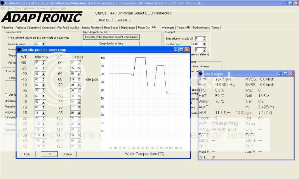
This picture illustrates the idle valve's unwillingness to cooperate, or more accurately, the computer's unwillingness. You can see the botched up table calling for 90 idle effort, but the gauge window clearly shows only 60.
EDIT: Just flashed V12 firmware and whaddya know, the idle valve works as it should. So in conclusion, V13 is a steaming pile.
For accel enrich I'm using MAP prediction as thats what all the FD/FC basemaps seems to have and everything I've read so far suggested to use it. At this point I've mainly tried adjusting the asynch gain and double asynch gain to no effect. When I crack the throttle open it goes extreme lean every time. It may also be worth mentioning that my primary injectors are mounted on the lower inlet manifold in line with the secondaries. So they're in a less desirable location that a normal injected rotary, but I don't see it being an issue as they're no further away than an injection perfection throttlebody or similar.
Yes, the TPS is nice and smooth in the logs. Using megalogviewer for visual representation. TPS is calibrated correctly.
Map filtering is set to > 70kpa
Current file is attached. The setup of the engine is a 12a extend port, SDR t04 turbo manifold (shitty wastegate pipe design but holds boost at 6psi just fine directly off the wastegate spring) T04z turbo, s4 lower inlet manifold with s6 upper, 4x ID1000's, chinese intercooler, innovate mtx-l, select 440d... let me know if I've left out critical components.
Using VE maps
Injector dead times I haven't touched as the ECU has that pre-done for ID1000's, at least I thought it did.
I know plenty of people are running them fine, that's why I decided to go for something like this instead of megasquirt again. I didn't feel like having terrible headaches, but here we are, terrible headaches with basic stuff that should be right out of the box. After seeing what happened with the bleedingly obvious wastegate values being grayed out using the latest V13 download, I'm left wondering what else is wrong with the software/firmware on this thing. Well for one thing, I'm pretty sure the idle control part of the software is fucked. What else?
Thanks a bunch for your input mate, I'll be interested to hear what your further thoughts are.
This picture illustrates the idle valve's unwillingness to cooperate, or more accurately, the computer's unwillingness. You can see the botched up table calling for 90 idle effort, but the gauge window clearly shows only 60.
EDIT: Just flashed V12 firmware and whaddya know, the idle valve works as it should. So in conclusion, V13 is a steaming pile.

I'm on v13, and got my idle pretty well in open loop, still working on it before i move to closed loop.
Prior to me getting to work well, I had "ExtIn 1/64 Elec Load (NB MX5/Miata" checked on accident, which sounds to me like what you are going through. Coolant base idle and all load inputs were not functioning or making the IAC move at all, it was just stuck at the minimum value.
Prior to me getting to work well, I had "ExtIn 1/64 Elec Load (NB MX5/Miata" checked on accident, which sounds to me like what you are going through. Coolant base idle and all load inputs were not functioning or making the IAC move at all, it was just stuck at the minimum value.
It is on the idle screen, it is adjacent to the "extra effort for elec load 1" or under the coolant based idle box in your screenshot.
Edit: Just looked at your map in v13 software, and that box is indeed checked.
Your predicted map table looks the same as mine. Are you seeing the lean spot via logs, or while driving? Here is one of my logs from earlier today. As you can see it is about a half second to full second before it returns to normal AFRs. This was from a "Decel fuel cut" or off throttle cruise to back on throttle. There is no noticeable affect in driving, but I can see where you are alarmed.
372.951 1292 -5.92 0 86 190 196 - -
373.31 1333 -3.88 0 86 190 196 22.3 13.1
373.404 1321 -4.25 0 86 190 196 22.3 13.1
373.731 1378 -4.77 0 86 190 196 15.3 13.1
373.887 1404 -5.03 0 86 190 196 14.9 13.2
374.152 1402 -5.14 0 86 190 196 13.7 13.2
I've played with my predicted map table to get it smooth, and the logs still show the above. I want to attribute it to lag of the AFR sensor, but as you can also see, it is about a full second and it is back to normal afrs.
My injector times once I get back on throttle also make sense, so I'm not too worried with that shows on the log.
BTW, also looking at your map, I believe you set your injectors wrong.
It has been stated by Andy in a video and probably some literature he wrote, but for staging to work, you need to set your primary injector type to "dead time/flow" under the tuning mode tab, then under the corrections tab you need to set your dead time corrections for "Primary" and "Secondary" should be straight forward here.
It has been stated by Andy in a video and probably some literature he wrote, but for staging to work, you need to set your primary injector type to "dead time/flow" under the tuning mode tab, then under the corrections tab you need to set your dead time corrections for "Primary" and "Secondary" should be straight forward here.
Arrogant Wankeler
Joined: Nov 2006
Posts: 1,009
Likes: 233
From: Hunter Valley NSW Australia
No air temp compensation for fuel? May want to throw in an ideal gas law line?
Is there a vac ref just after the throttle body or on the plenum going spare? It has been a while since I looked at one, probably better than off an individual runner.
I have revised some stuff in the file with notes attached.
Closed loop boost control >> If you put integer values in the proportional gain (can keep zeros in the integral and diff if you wish) you can then edit the closed loop target boost values in wastegate control. Basically it can't work closed loop without at least a proportional PID parameter. There are several threads on this (regarding people observed good PID values on different setups) on the adaptronic forum.
It may pay to use a finer mesh for mapping, not so much for revs but having a denser map around idle speed means you can run a "timing" well so that idle speed settles and if it drops the additional torque of a bit more timing just below target speed catches it. Is your timing true crank degrees or offset to the ATDC mark, ported motors seem to be happy around 7 deg true at idle? I did this on the Haltech in OLD MAN's FC (he was asking for help on AR) which had IAC disconnected and I cleaned the idle fuelling up a bit (some numpty had it on a "closed throttle map"). Got it starting and idling happily at OEM revs with no IAC at all I will note his EP 13b idled happiest around 12.7 AFR on the gauge. Even if you go down to 250rpm increments across the whole map that only takes you to 7500 IIRC, the ecu carries the last table values to higher rpm so you could still run to an 8000+ rpm limit, would obviously go a bit rich there. (I'm surprised you aren't revving it out more, even with a 500rpm optimistic tach I generally run my 12a off the end of the dial and an running out to 8350 with the PFC in the FD which is near stock)
As above, does the engine actually stumble on throttle transient or is the wideband just slow to catch up? It should still not read lean at all (unless throttle off overrun is active) if the map prediction/asynchronous gain is perfect.
Just noticed the predicted map at low rpm low throttle openings is **** about to what it should be, it will go closer to atmospheric at low throttle openings at low revs than it will at high, table needs tweaking. You can do some logging playing with throttle at various rpm to find the pressures it will sit at when you crack it various amounts to improve the table.
Is there a vac ref just after the throttle body or on the plenum going spare? It has been a while since I looked at one, probably better than off an individual runner.
I have revised some stuff in the file with notes attached.
Closed loop boost control
>> If you put integer values in the proportional gain (can keep zeros in the integral and diff if you wish) you can then edit the closed loop target boost values in wastegate control. Basically it can't work closed loop without at least a proportional PID parameter. There are several threads on this (regarding people observed good PID values on different setups) on the adaptronic forum.It may pay to use a finer mesh for mapping, not so much for revs but having a denser map around idle speed means you can run a "timing" well so that idle speed settles and if it drops the additional torque of a bit more timing just below target speed catches it. Is your timing true crank degrees or offset to the ATDC mark, ported motors seem to be happy around 7 deg true at idle? I did this on the Haltech in OLD MAN's FC (he was asking for help on AR) which had IAC disconnected and I cleaned the idle fuelling up a bit (some numpty had it on a "closed throttle map"). Got it starting and idling happily at OEM revs with no IAC at all
I will note his EP 13b idled happiest around 12.7 AFR on the gauge. Even if you go down to 250rpm increments across the whole map that only takes you to 7500 IIRC, the ecu carries the last table values to higher rpm so you could still run to an 8000+ rpm limit, would obviously go a bit rich there. (I'm surprised you aren't revving it out more, even with a 500rpm optimistic tach I generally run my 12a off the end of the dial and an running out to 8350 with the PFC in the FD which is near stock)As above, does the engine actually stumble on throttle transient or is the wideband just slow to catch up? It should still not read lean at all (unless throttle off overrun is active) if the map prediction/asynchronous gain is perfect.
Just noticed the predicted map at low rpm low throttle openings is **** about to what it should be, it will go closer to atmospheric at low throttle openings at low revs than it will at high, table needs tweaking. You can do some logging playing with throttle at various rpm to find the pressures it will sit at when you crack it various amounts to improve the table.
Senior Member
Joined: Jun 2004
Posts: 263
Likes: 2
From: Australia
Thanks for that slides. The base maps I had must have been done in V12 software and the stupid Miata setting was absent with it checked as default when the V13 software was installed. Frustrating, but glad to be on the other side of it.
I changed the vac reference point to one near the throttlebody, made no difference to anything.
Closed loop boost control is working really well, holding 11psi nicely. As for the rev limit, I've started with it very conservative as I want it to live and just last week it ate it's torrington bearings due to an incompetent engine builder, so I don't trust it yet. I literally did the whole turbo conversion in one day, so just building trust in the system.
My timing is true crank degrees.
The engine stumbles on throttle transient, badly. The car is basically undrivable. I spent 3 or 4 hours trying to get the car to respond to throttle blips with a cluey mate of mine but it absolutely refuses to cooperate. Tried both map prediction tables and the ol' style. No luck. I had a look at a bunch of people's tunes, tried their settings, tried everything from high to low values, different transition times, asynch gains etc. Car drives like complete garbage.
Also it stalls every time without fail when you come to a stop and I can't for the life of me work out why. I'll get a log up at some point but I can't see any reason for it. The AFR's look fine, timing looks ok. It just falls over. Really ready to burn the car to the ground haha.
For the mean time, here is a video of the rx7's spectacular throttle response. Couldn't really improve beyond this, no hope of getting it to rev cleanly. So far as I know, there's no Adaptronic gurus around here either.
Arrogant Wankeler
Joined: Nov 2006
Posts: 1,009
Likes: 233
From: Hunter Valley NSW Australia
Might be worth checking TPS calibration again or your threshold limits?
Have you tried it with the TPS sensitivity at different levels?
Maybe try some predicted map values a bit more like attached if you haven't already?
Tried toggling the tick boxes for open loop transient etc?
Have you had someone stand behind the car to see if you get any soot when you blip it? Or there is nothing?
Seems really strange.
Could you post a log of you free revving it like that?
Might be worth playing with the closed loop/dashpot idle checkboxes to see if there is any influence there for the stalling?
Arrogant Wankeler
Joined: Nov 2006
Posts: 1,009
Likes: 233
From: Hunter Valley NSW Australia
Would be really interesting to see what actual inj ms open times you are getting on transient vs steady state on load at those throttle/rpm points on the main fuel table.