
Turbos Explained


Thread Starter
Hoo Hoo Hoosiers

Joined: Nov 2010
Posts: 72
Likes: 3
From: Austin, TX
Turbos Explained
So as I have been viewing various threads on here I constantly seem to get lost in the terminology, especially when it comes to turbochargers. It always starts out as an innocent question and then people will start debating about mathematical equations and all kinds of stuff that I have no idea what they are talking about. And I am sure I am not alone. So i decided that I would repost this informative thread I found that explains a little bit about turbochargers and the basic principles and terminology. All the credit goes to Dirty25RS from the C30World Forums, I am simply reposting it. I hope this will help enlighten beginners (like me) on the terminology and principles that experts start throwing around on this forum when it comes to turbocharging.
Basics: How A Turbo Works
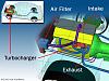
Turbochargers are a type of forced induction system. They compress the air flowing into the engine. The advantage of compressing the air is that it lets the engine squeeze more air into a cylinder, and more air means that more fuel can be added. Therefore, you get more power from each explosion in each cylinder. A turbocharged engine produces more power overall than the same engine without the charging. This can significantly improve the power-to-weight ratio for the engine
In order to achieve this boost, the turbocharger uses the exhaust flow from the engine to spin a turbine, which in turn spins an air pump. The turbine in the turbocharger spins at speeds of up to 150,000 rotations per minute (rpm) -- that's about 30 times faster than most car engines can go. And since it is hooked up to the exhaust, the temperatures in the turbine are also very high.
One of the surest ways to get more power out of an engine is to increase the amount of air and fuel that it can burn. One way to do this is to add cylinders or make the current cylinders bigger. Sometimes these changes may not be feasible -- a turbo can be a simpler, more compact way to add power, especially for an aftermarket accessory.
Turbochargers allow an engine to burn more fuel and air by packing more into the existing cylinders. The typical boost provided by a turbocharger is 6 to 8 pounds per square inch (psi). Since normal atmospheric pressure is 14.7 psi at sea level, you can see that you are getting about 50 percent more air into the engine. Therefore, you would expect to get 50 percent more power. It's not perfectly efficient, so you might get a 30- to 40-percent improvement instead.
One cause of the inefficiency comes from the fact that the power to spin the turbine is not free. Having a turbine in the exhaust flow increases the restriction in the exhaust. This means that on the exhaust stroke, the engine has to push against a higher back-pressure. This subtracts a little bit of power from the cylinders that are firing at the same time.*
Too Much Boost?
With air being pumped into the cylinders under pressure by the turbocharger, and then being further compressed by the piston, there is more danger of knock. Knocking happens because as you compress air, the temperature of the air increases. The temperature may increase enough to ignite the fuel before the spark plug fires. Cars with turbochargers often need to run on higher octane fuel to avoid knock. If the boost pressure is really high, the compression ratio of the engine may have to be reduced to avoid knocking.
Ok now that thats out of the way lets go over some terms you need to familiarize yourself with.
Airflow - Increasing this is the important thing that a turbocharger does, not boost. More air + more fuel = more power
Boost - the increased pressure in the intake that a turbocharger generates
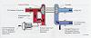
Compressor - the part of the turbo that does all the work. It mechanically increases the flowrate of the air by doing work to the air via the compressor wheel and compressor housing.
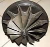
Compressor wheel - a fan of sorts. in a turbo compressor its designed to take air in axially and change its direction and increase its velocity centrifugally.
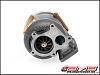
Compressor housing - the thing that holds the compressor wheel, lol. Actually its designed as a centrifugal nozzle. As the air radiates outward from the compressor wheel, the cross sectional area of the compressor housing is reduced. This is where the compression happens. It also collects the air in an orderly fashion and directs it out the discharge outlet. This is what gives it its "snail" appearance.
Axle - Sometimes called the propshaft, this is the thing that connects the turbine wheel to the compressor wheel. It does the exact same job as a vehicle axle in that it moves torque from A to B.
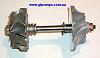
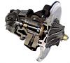
Cartridge Section - this is a portion inbetween the compressor and turbine. The axle runs through the middle of it. It contains bearings for the axle to rotate against. Its main job is to keep the axle straight and not wobbling and to keep it cool and lubricated. Oil flows in and out of this section. In most modern vehicles so does coolant. There are turbos being developed that are completely closed lubrication and are not hooked up to the engine oil/coolant channels but thats a whole other discussion.
Basics: How A Turbo Works
Turbochargers are a type of forced induction system. They compress the air flowing into the engine. The advantage of compressing the air is that it lets the engine squeeze more air into a cylinder, and more air means that more fuel can be added. Therefore, you get more power from each explosion in each cylinder. A turbocharged engine produces more power overall than the same engine without the charging. This can significantly improve the power-to-weight ratio for the engine
In order to achieve this boost, the turbocharger uses the exhaust flow from the engine to spin a turbine, which in turn spins an air pump. The turbine in the turbocharger spins at speeds of up to 150,000 rotations per minute (rpm) -- that's about 30 times faster than most car engines can go. And since it is hooked up to the exhaust, the temperatures in the turbine are also very high.
One of the surest ways to get more power out of an engine is to increase the amount of air and fuel that it can burn. One way to do this is to add cylinders or make the current cylinders bigger. Sometimes these changes may not be feasible -- a turbo can be a simpler, more compact way to add power, especially for an aftermarket accessory.
Turbochargers allow an engine to burn more fuel and air by packing more into the existing cylinders. The typical boost provided by a turbocharger is 6 to 8 pounds per square inch (psi). Since normal atmospheric pressure is 14.7 psi at sea level, you can see that you are getting about 50 percent more air into the engine. Therefore, you would expect to get 50 percent more power. It's not perfectly efficient, so you might get a 30- to 40-percent improvement instead.
One cause of the inefficiency comes from the fact that the power to spin the turbine is not free. Having a turbine in the exhaust flow increases the restriction in the exhaust. This means that on the exhaust stroke, the engine has to push against a higher back-pressure. This subtracts a little bit of power from the cylinders that are firing at the same time.*


Too Much Boost?
With air being pumped into the cylinders under pressure by the turbocharger, and then being further compressed by the piston, there is more danger of knock. Knocking happens because as you compress air, the temperature of the air increases. The temperature may increase enough to ignite the fuel before the spark plug fires. Cars with turbochargers often need to run on higher octane fuel to avoid knock. If the boost pressure is really high, the compression ratio of the engine may have to be reduced to avoid knocking.
Ok now that thats out of the way lets go over some terms you need to familiarize yourself with.
Airflow - Increasing this is the important thing that a turbocharger does, not boost. More air + more fuel = more power
Boost - the increased pressure in the intake that a turbocharger generates
Compressor - the part of the turbo that does all the work. It mechanically increases the flowrate of the air by doing work to the air via the compressor wheel and compressor housing.
Compressor wheel - a fan of sorts. in a turbo compressor its designed to take air in axially and change its direction and increase its velocity centrifugally.

Compressor housing - the thing that holds the compressor wheel, lol. Actually its designed as a centrifugal nozzle. As the air radiates outward from the compressor wheel, the cross sectional area of the compressor housing is reduced. This is where the compression happens. It also collects the air in an orderly fashion and directs it out the discharge outlet. This is what gives it its "snail" appearance.

Axle - Sometimes called the propshaft, this is the thing that connects the turbine wheel to the compressor wheel. It does the exact same job as a vehicle axle in that it moves torque from A to B.

Cartridge Section - this is a portion inbetween the compressor and turbine. The axle runs through the middle of it. It contains bearings for the axle to rotate against. Its main job is to keep the axle straight and not wobbling and to keep it cool and lubricated. Oil flows in and out of this section. In most modern vehicles so does coolant. There are turbos being developed that are completely closed lubrication and are not hooked up to the engine oil/coolant channels but thats a whole other discussion.

Thread Starter
Hoo Hoo Hoosiers
Joined: Nov 2010
Posts: 72
Likes: 3
From: Austin, TX
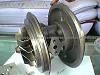
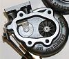
Turbine - The part of the turbo designed to harness exhaust energy. Exhaust gases enter it perpendicular to the turbine wheel at very high temperatures and moderately high pressure and exit axially at lower temperatures and pressures.
Turbine wheel - mechanically turns exhaust flow energy into rotational energy and feeds it to the compressor wheel via the axle.
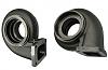
Turbine Housing - Collects the exhaust gases and directs them through the turbine wheel and out to the rest of the exhaust.
Bearing - This is in the cartridge and keeps the axle straight and cool. It is designed to be a low friction interface between the axle and the cartridge.
Bearings come in many forms.
Journal bearings are basically one surface inside of another. They are cheap and easy to manufacture. They used to be considered inferior to ball-bearing turbos but since they are cheap and easy to manufacture, much R&D money has been put into making them perform better, and its starting to pay dividends.
Thrust bearings are a type of roller bearing. They have rollers with a geometry as such that they prevent the object within the bearing from "thrusting" through the bearing
Ball-bearings are bearings with rolling ***** in them. They are very low friction because of reduced areas in contact compared to roller or journal bearings (image the contact area between a super hard metal sphere and a flat surface). For ages they have been the bread and butter of turbocharger bearings
Ceramic bearings - a material that can be used in any type of bearing characterized by high heat capacity and extreme hardness.
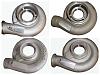
A/R ratio - A/R (Area/Radius) describes a geometric characteristic of all compressor and turbine housings. Technically, it is defined as: the inlet (or, for compressor housings, the discharge) cross-sectional area divided by the radius from the turbo centerline to the centroid of that area.
Compressor A/R - Compressor performance is comparatively insensitive to changes in A/R. Larger A/R housings are sometimes used to optimize performance of low boost applications, and smaller A/R are used for high boost applications. However, as this influence of A/R on compressor performance is minor, there are not A/R options available for compressor housings.

Turbine wheel - mechanically turns exhaust flow energy into rotational energy and feeds it to the compressor wheel via the axle.

Turbine Housing - Collects the exhaust gases and directs them through the turbine wheel and out to the rest of the exhaust.

Bearing - This is in the cartridge and keeps the axle straight and cool. It is designed to be a low friction interface between the axle and the cartridge.
Bearings come in many forms.
Journal bearings are basically one surface inside of another. They are cheap and easy to manufacture. They used to be considered inferior to ball-bearing turbos but since they are cheap and easy to manufacture, much R&D money has been put into making them perform better, and its starting to pay dividends.
Thrust bearings are a type of roller bearing. They have rollers with a geometry as such that they prevent the object within the bearing from "thrusting" through the bearing
Ball-bearings are bearings with rolling ***** in them. They are very low friction because of reduced areas in contact compared to roller or journal bearings (image the contact area between a super hard metal sphere and a flat surface). For ages they have been the bread and butter of turbocharger bearings
Ceramic bearings - a material that can be used in any type of bearing characterized by high heat capacity and extreme hardness.

A/R ratio - A/R (Area/Radius) describes a geometric characteristic of all compressor and turbine housings. Technically, it is defined as: the inlet (or, for compressor housings, the discharge) cross-sectional area divided by the radius from the turbo centerline to the centroid of that area.
Compressor A/R - Compressor performance is comparatively insensitive to changes in A/R. Larger A/R housings are sometimes used to optimize performance of low boost applications, and smaller A/R are used for high boost applications. However, as this influence of A/R on compressor performance is minor, there are not A/R options available for compressor housings.
Thread Starter
Hoo Hoo Hoosiers
Joined: Nov 2010
Posts: 72
Likes: 3
From: Austin, TX
Turbine A/R - Turbine performance is greatly affected by changing the A/R of the housing, as it is used to adjust the flow capacity of the turbine. Using a smaller A/R will increase the exhaust gas velocity into the turbine wheel. This provides increased turbine power at lower engine speeds, resulting in a quicker boost rise. However, a small A/R also causes the flow to enter the wheel more tangentially, which reduces the ultimate flow capacity of the turbine wheel. This will tend to increase exhaust backpressure and hence reduce the engine's ability to "breathe" effectively at high RPM, adversely affecting peak engine power.
Conversely, using a larger A/R will lower exhaust gas velocity, and delay boost rise. The flow in a larger A/R housing enters the wheel in a more radial fashion, increasing the wheel's effective flow capacity, resulting in lower backpressure and better power at higher engine speeds.
When deciding between A/R options, be realistic with the intended vehicle use and use the A/R to bias the performance toward the desired powerband characteristic.
Here's a simplistic look at comparing turbine housing geometry with different applications. By comparing different turbine housing A/R, it is often possible to determine the intended use of the system.
Imagine two 3.5L engines both using GT30R turbochargers. The only difference between the two engines is a different turbine housing A/R; otherwise the two engines are identical:
1. Engine #1 has turbine housing with an A/R of 0.63
2. Engine #2 has a turbine housing with an A/R of 1.06.
What can we infer about the intended use and the turbocharger matching for each engine?
Engine#1: This engine is using a smaller A/R turbine housing (0.63) thus biased more towards low-end torque and optimal boost response. Many would describe this as being more "fun" to drive on the street, as normal daily driving habits tend to favor transient response. However, at higher engine speeds, this smaller A/R housing will result in high backpressure, which can result in a loss of top end power. This type of engine performance is desirable for street applications where the low speed boost response and transient conditions are more important than top end power.
Engine #2: This engine is using a larger A/R turbine housing (1.06) and is biased towards peak horsepower, while sacrificing transient response and torque at very low engine speeds. The larger A/R turbine housing will continue to minimize backpressure at high rpm, to the benefit of engine peak power. On the other hand, this will also raise the engine speed at which the turbo can provide boost, increasing time to boost. The performance of Engine #2 is more desirable for racing applications than Engine #1 since Engine #2 will be operating at high engine speeds most of the time.
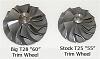
Trim - Trim is a common term used when talking about or describing turbochargers. For example, you may hear someone say "I have a GT2871R ' 56 Trim ' turbocharger. What is 'Trim?' Trim is a term to express the relationship between the inducer* and exducer* of both turbine and compressor wheels. More accurately, it is an area ratio.
* The inducer diameter is defined as the diameter where the air enters the wheel, whereas the exducer diameter is defined as the diameter where the air exits the wheel.
Based on aerodynamics and air entry paths, the inducer for a compressor wheel is the smaller diameter. For turbine wheels, the inducer it is the larger diameter.
Wastegate - the wastegate allows exhaust gas to bypass the turbine wheel. This is the mechanical device that regulates boost. Your boost controller/boost solenoid works by actuating the wastegate. They can be internal to the turbine housing or external. Higher HP applications usually prefer external because internal gates are limited in size and the turbulence they generate makes boost control difficult and can limit peak boost.
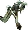
Blow off Valve/Bypass Valve - This valve allows compressed air to flow out of the intake into the atmosphere(Blow off valve) or back into the intake pre-compressor (bypass valve). It is needed so that you dont have boost when you dont want it (shifting, braking, etc). You only need a new blow off valve if your current one wont hold the pressure you are trying to achieve. You dont get more power just by putting one of these on and it can have negative effects on air/fuel ratio and misfires.
BOV
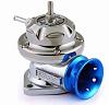
BPV
BOV
Conversely, using a larger A/R will lower exhaust gas velocity, and delay boost rise. The flow in a larger A/R housing enters the wheel in a more radial fashion, increasing the wheel's effective flow capacity, resulting in lower backpressure and better power at higher engine speeds.
When deciding between A/R options, be realistic with the intended vehicle use and use the A/R to bias the performance toward the desired powerband characteristic.
Here's a simplistic look at comparing turbine housing geometry with different applications. By comparing different turbine housing A/R, it is often possible to determine the intended use of the system.
Imagine two 3.5L engines both using GT30R turbochargers. The only difference between the two engines is a different turbine housing A/R; otherwise the two engines are identical:
1. Engine #1 has turbine housing with an A/R of 0.63
2. Engine #2 has a turbine housing with an A/R of 1.06.
What can we infer about the intended use and the turbocharger matching for each engine?
Engine#1: This engine is using a smaller A/R turbine housing (0.63) thus biased more towards low-end torque and optimal boost response. Many would describe this as being more "fun" to drive on the street, as normal daily driving habits tend to favor transient response. However, at higher engine speeds, this smaller A/R housing will result in high backpressure, which can result in a loss of top end power. This type of engine performance is desirable for street applications where the low speed boost response and transient conditions are more important than top end power.
Engine #2: This engine is using a larger A/R turbine housing (1.06) and is biased towards peak horsepower, while sacrificing transient response and torque at very low engine speeds. The larger A/R turbine housing will continue to minimize backpressure at high rpm, to the benefit of engine peak power. On the other hand, this will also raise the engine speed at which the turbo can provide boost, increasing time to boost. The performance of Engine #2 is more desirable for racing applications than Engine #1 since Engine #2 will be operating at high engine speeds most of the time.
Trim - Trim is a common term used when talking about or describing turbochargers. For example, you may hear someone say "I have a GT2871R ' 56 Trim ' turbocharger. What is 'Trim?' Trim is a term to express the relationship between the inducer* and exducer* of both turbine and compressor wheels. More accurately, it is an area ratio.
* The inducer diameter is defined as the diameter where the air enters the wheel, whereas the exducer diameter is defined as the diameter where the air exits the wheel.
Based on aerodynamics and air entry paths, the inducer for a compressor wheel is the smaller diameter. For turbine wheels, the inducer it is the larger diameter.
Wastegate - the wastegate allows exhaust gas to bypass the turbine wheel. This is the mechanical device that regulates boost. Your boost controller/boost solenoid works by actuating the wastegate. They can be internal to the turbine housing or external. Higher HP applications usually prefer external because internal gates are limited in size and the turbulence they generate makes boost control difficult and can limit peak boost.


Blow off Valve/Bypass Valve - This valve allows compressed air to flow out of the intake into the atmosphere(Blow off valve) or back into the intake pre-compressor (bypass valve). It is needed so that you dont have boost when you dont want it (shifting, braking, etc). You only need a new blow off valve if your current one wont hold the pressure you are trying to achieve. You dont get more power just by putting one of these on and it can have negative effects on air/fuel ratio and misfires.
BOV

BPV

BOV
Thread Starter
Hoo Hoo Hoosiers
Joined: Nov 2010
Posts: 72
Likes: 3
From: Austin, TX
Important Concepts:
Boost =not= Boost....
20psi on your stock K04 turbo =not= 20psi on a 3071R turbo
A 3071R is more efficient at flowing air than a k04. @20psi a k04 may flow 30lb/min whereas a 3071R may flow 50lb/min and its that airflow that makes power, and if its too much...blows motors
Max Boost/Max Flowrate
Turbo's have a maximum intake air flowrate and a maximum boost. You would think that you could just keep the wastegate shut and keep throwing more and more exhaust through the turbine and thus build more and more boost (and heat) and flow but there is an upper limit.
It has to do with the bearings/axle/compressor wheels. They are only designed to spin so fast. For a typical turbo its between 80,000rpm and 150,000rpm. Manufacturers usually dont specify a maximum rpm for their turbos, since you really have no way to measure it. So they specify the corresponding airflow (lb/min, cfm, cc/min, etc) and/or the corresponding boost pressure (psi, bar, kPa, mmHg, mmH20, Kgf/cm^2 etc.) to that maximum rpm.
Turbo lag.....
An object at rest, stays at rest. F=ma
A bigger compressor wheel / turbine wheel (i.e. a bigger turbo) has more inertia and therefore takes more turbine airflow to get it spinning. The airflow through the turbine is proportional to the engine rpm, because, from the turbo's point of view, all the engine is is a big hot air pump.
So with a bigger turbo you will reach peak boost at a higher rpm than a smaller turbo. This is what I am calling turbo lag.
There are a lot of things you can do with A/R ratio, trim, and mixing and matching compressor housing sizes and turbine sizes to optimize your total airflow and amount of turbolag for your given application. I have given you the basic tools to understand these relationships.
This is the art of turbo sizing.
Fighting Turbo Lag
If you want to build boost fast your primary goal is get the exhaust gas to the turbine as hot, fast, and pressurized as possible.
Ways to do it:
1. shorten the distance between the exhaust valve and the turbine (see your volvo for a good example, or an evo (both 4-12inches)....see subaru for a bad example (4 or so feet))
2. port your exhaust manifold. less loss along the sides of the pipes
3. insulate your exhaust manifold. heat wrap, ceramic coatings, reflective coatings etc. keep the heat in the exhaust where you want it and out of the engine bay where its useless.
4. better boost control. Sometimes you will find that its purely the electronics and the wastegate holding you back. This is when you look at aftermarket boost solonoids/controllers (like turbosmart eboost2) and external wastegates
Anti-lag
There are multiple ways antilag works but the basic idea is that it builds boost w/o engine load. You can't build boost off the line because there is no engine load, no resistance. resistance means the engine has to make more power so it sparks somewhat earlier, injects more fuel and more air and the piston is harder to push down so the mixture gets real hot. Turbines are more efficient the hotter and more pressurized the exhaust flow flowing through them is.
Some antilag systems will leave the exhaust valve open during combustion to literally blow flames through the turbine.
Some will delay the spark untill after top dead center for the same effect.
I've even seen complicated system where compressed intake air is direct straight through the turbine with a secondary igniter, basically more like a Jet engine.
Application
What do you want to do with your car?
Road race? - whats your competition? are you going to high speed tracks (high speed ring?) or low speed tracks (autumn ring)? Are you going to have enough track to spool up your giant GT40R turbo with your 2.0L motor? Is your K04 going to choke at the end of each straight because the engine can flow more air than the turbo can give it?
AutoX? - Basically extreme autumn ring. low end torque wins here. This is a competition dominated by the fastest spool (least turbo lag).
Drag racing? - You dont want to bog off the launch with an oversized turbo, but you dont want to be choked at thend by a small one. Serious small engine turbocharged drag racers usually use a humongous turbo with antilag. That way they have peak boost off the line and hold it the whole way down the track
Daily drive? - I never no what to do with you people who just have money to throw away, but nonetheless I have a turbo for you!
Effect of engine size on turbo spool/lag
Remember, from your turbocharger's point of view, all the engine is is a air pump that pressurizes and heats up airflow into the turbine. The larger displacement engine you have, the bigger the pump. The bigger the pump, the more airflow at any given rpm. The more airflow at a given RPM, the more boost pressure can be made at that rpm.
Conclusion: The bigger the engine the faster the turbo will reach peak boost. There's no replacement for displacement.
If you have a big motor, a small turbo compressor wont be able to supply it enough air, or a small turbine will be too much of a restriction to exhaust flow.
So on a 2.0L engine, a 35R might be oversized, but on a 7.0L it might be undersized (you might need two).
Thread Starter
Hoo Hoo Hoosiers
Joined: Nov 2010
Posts: 72
Likes: 3
From: Austin, TX
How To Read a Compressor Map
Compressor maps tell you how the compressor part of the turbine works. They tell you at what pressure you will get what flow, and what the compressor efficiency is. If the compressor efficiency is low but the pressure is high, that means that you are not flowing more air, that you are just making more pressure because the compressed air is hotter. This is a bad thing because, as I said, airflow is whats important, not boost pressure.
This guide isn't meant to be an in-depth look at turbo sizing, but rather to give the reader a working knowledge of how to read compressor maps. In other words, to decipher what all those swirling lines mean when choosing a turbo compressor.
Terminology
Compressor - This is the "cold" side of the turbo that sucks in intake air and compresses it for the engine to later combust with fuel.
Turbine - This is the "hot" side of the turbo. Hot exhaust gasses pass through it, expanding and cooling. This expansion spins a turbine wheel that drives the compressor wheel via a shaft. Unfortunately turbo manufacturers don't make turbine maps available to the general public.
Absolute Pressure - This is pressure referenced from a pure vacuum. Most calculations done involving compressors use absolute pressure. Note - 1 atmosphere = ~14.7 psia (Absolute pressure in pounds per square inch) = 0 psig (gage pressure in pounds per square inch). Your boost gauge reads in psig, referenced to local atmospheric pressure.
ONTO THE MAPS
Surge - This is lowest amount of airflow a compressor can supply at a given pressure ratio(getting to that). Any pressure above this at this airflow, the compressor will "gulp" air. This is not good for your turbo, or your power output. Fortunately you have to saddle a pretty huge compressor with a small turbine to really worry about this effect.
Here is a compressor map with the surge line highlighted in red.
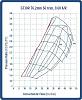
On the X-axis(horizontal) you'll notice the mass airflow of the compressor in lbs/min. On the Y-axis there is the Pressure Ratio. Pressure ratio is defined as follows:
Atmospheric Pressure + Boost Pressure = Pressure Ratio
Atmospheric Pressure
So the astute reader will notice a pressure ratio of 1.0 is the exact same as atmospheric. A pressure ratio of 2.0 is equivalent to 1 atmosphere or ~14.7 psig in your intake manifold. Without concrete data proving otherwise, it is always the best course of action to assume the pressure is ambient at the compressor inlet and make note of the pressure drops of the system will in the end cause less horsepower to be produced than the mass flowrate of the turbo would suggest.
The oval shaped rings on the compressor map are efficiency islands. These are regions where the compressor has approximately the same efficiency at compressing the air. Of course, the higher the efficiency the better since the compressor will be introducing less unneeded heat into the charge air. Note that as you go away from the maximum efficiency island, you always go down in efficiency. By the time you're off the map you're usually in the <60% range, which is not a good thing.
The lines that slope from the surge line to the right and down across the efficiency islands are constant speed lines. This would be really useful if you could match up the speed of the compressor to the speed of the turbine and find out its efficiency and mass flowrate for that shaft speed, but since we don't have turbine maps we're kind of at a disadvantage there for picking the ultimate turbo match. The maps used here out of Garrett's publicly available catalog aren't too detailed. Some maps will have much more data like putting RPM values on the speed lines, more efficiency islands etc.
I won't go into the hard equation to calculate the mass airflow of the engine, as it really doesn't gain anybody any further insight into the turbo selection process. The only important things to understand that the big factors in how much mass airflow an engine is consuming are:
Engine Displacement
Volumetric Efficiency(how well the engine breathes)
Pressure at the inlet valves(BOOST!)
RPM
By altering these things(more displacement, cams to increase VE, more boost, more RPMs) you can make the engine combust more air and make more power.
Here I'll look at a GT30R turbo on an S52B32 engine with a VE of 90%, displacement of 3.2L and maximum RPM of 7000. For the first go, we'll see what happens at a modest boost level of ~8.7 psi(pressure ratio of 1.6).
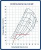
How I evaluate compressor maps is to note the airflow at 2000 RPM. Find that on the X-axis and draw a straight line from that point at a PR of 1 to the airflow at 3000 RPM at your desired PR(1.6 in this case). This gives you an idea of how a typical turbo will look when spooling up, and let you know if it's at a risk of surging. From there, the line should stay at that PR all the way to the airflow at redline ~39 lb/min here.
As you can see, surge is not a problem here, but this turbo sure does look a bit too small for this sized engine! It goes off the map just before redline, so that means it is very inefficient at higher revs.
Let's see what happens when we up the boost to ~17.4 psi(PR of 2.2).
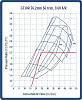
No risk of surge due to this being a large engine for the turbo, but boy does it ever get REALLY inefficient at higher revs. Past 6000 RPM it is again off the map.
Let's go to a slightly larger turbo, a GT35R, to see the difference. Same boost of 17.4 psi(PR of 2.2).
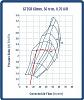
Now that is more like it! Notice how the engine spends a good amount of time in the really efficient islands, and the turbo is still at 72% efficiency all the way to redline. I'd think this turbo would be putting out in the 450-500rwhp range at this boost on this engine, and that's probably being a bit conservative. If the VE of the engine was even higher(which it can be), this turbo could still put out even more power. The compressor map also suggests it has a bit more headroom on this particular engine.
I hope that was helpful to everybody, and gives people a start in the right direction on reading compressor maps themselves.
Enjoy boost junkies!


Trending Topics

Thread
Thread Starter
Forum
Replies
Last Post
trickster
2nd Generation Specific (1986-1992)
25
Jul 1, 2023 04:40 PM