Taurus SHO 2-Speed 4500CFM Electric Radiator Fan
 11-27-09, 09:43 PM
#1
Taurus SHO 2-Speed 4500CFM Electric Radiator Fan
Apparently this fan is common amongst the FC rx7 guys, but I can't find a single instance where someone used this on an FD. I decided track cooling is my top priority and ordered one for my FD. I will be attempting to fit and wire this fan. If anyone has installed this on their FD, or knows how, please post or PM.
For wiring, I would like to wire this so low speed comes on at 90*C (or wherever KDR set my lower speed fan-on with the PFC) and high speed comes on at 99*C. Second best alternative would be to just have a high speed switch inside the cabin for track duty. (The best reference I found for wiring is in the FC boards here: https://www.rx7club.com/showthread.p...ghlight=taurus. I imagine there are some significant differences between rigging this up to an FD vs. FC)
Secondly, any ideas on sealing the gaps between the shroud and the rad would be appreciated. I would like this to look as clean as possible, but function over form when it comes to cooling (I've been known to use duct tape on my I/C ducting). The relevant dimensions are as follows:
Fan Shroud 17"x22"
Koyo Core 13"x24"
Based on this it looks like I might be SOL trying to get this to seal up.
 11-27-09, 11:04 PM
#2
I can't tell you how many CFM the stock fans move off-hand, so I can't compare to what the SHO fans reportedly move. But why do you think the stock fans are a weak point in the FD cooling system? Especially given the apparent difficulty your going to have in getting any kind of seal with the SHO shroud.
11-28-09, 12:34 AM
#3
I haven't used the Taurus fan on FD but I have used a Flex-a-lite Black Magic 155 on an upgraded radiator mounted upright. And I can tell you that it didn't cool as well as the stock fans. the stock fans held the temperature more stably, probably due to the shrouding.
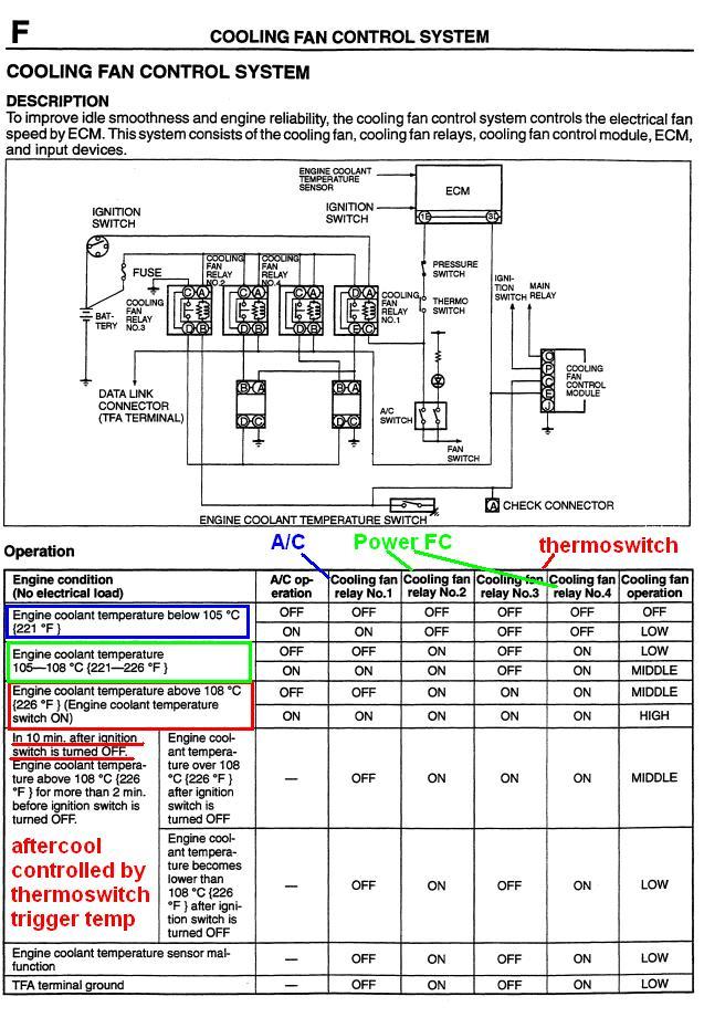
The three speeds of the factory units are also superior to the two speed design of the Taurus fan, with far less current draw. You just have to understand the wiring. By jumpering a wire or two you can have the PFC trigger the fans at medium speed (instead of low speed) and then have your max fan speed triggered by a thermoswitch. Also, the thermoswitch controls the aftercool control module. You won't get that feature with a Taurus fan.
The three speeds of the factory units are also superior to the two speed design of the Taurus fan, with far less current draw. You just have to understand the wiring. By jumpering a wire or two you can have the PFC trigger the fans at medium speed (instead of low speed) and then have your max fan speed triggered by a thermoswitch. Also, the thermoswitch controls the aftercool control module. You won't get that feature with a Taurus fan.
11-28-09, 01:00 AM
#4
if you have a PFC and stock thermoswitch, your fans will run at low speed until 108 C unless you turn on the A/C.
But take a look at the factory fan control diagram. You will see here that it is far superior to anything you can easily wire up yourself. The only real problem with it is that the trigger temps are a lot higher than we would like. Your stock fans are probably not running at their max possible speeds. Why not enhance what you have? It will be cheaper, cleaner, and IMO more effective than the Taurus fan.
To maximize the cooling capacity of the stock fans, your best bet would be to:
1) install an FC thermoswitch. This will bump your fan speed up at 95 C rather than 108. It will also make your fans come on when you shut the car off if the engine has hit 95 C sustained temps. There are actually lower temp FC thermoswitches available from the earlier series 4 models if you really want them.
2) You can wire it so that fan relay #1 can be triggered by the PFC or the A/C. In that way, every time the PFC is triggering the fans you will be at MEDIUM speed. If you are below that trigger temp and the A/C is on, you will be at LOW speed. If the A/C is off, the PFC has triggered the fans and the thermoswitch has been activated, you will be running at full speed.
These are the equivalent fan speeds that you would have running 108 C with the A/C on on a stock car.
So the new logic would be:
A/C ON, water temps below 90 C -- low speed
A/C OFF, water temps below 90 C -- fans off
A/C ON, water temps at 90-94 C -- medium speed
A/C OFF, water temps at 90-94 C -- medium speed (as opposed to low speed as you have now)
A/C ON, water temps at 95 C (thermoswitch temp) -- max speed
A/C OFF, water temps at 95 C (thermoswitch temp) -- max speed
Aftercool: engine runs at 95 C for 2+ minutes before shutdown, fans run at medium speed until temps drop below 95 C, when the fans will slow down to low speed. After ten minutes the fans will shut off. No major cutting or external switches are required with this wiring. It is idiot proof if installed correctly.
again, if you have a PFC and stock thermoswitch, your fans will run at low speed until 108 C unless you turn on the A/C. But if we wire the #1 relay in with the PFC trigger and install an FC thermoswitch, you will still have progressive fan control without wiring anything in, and your fans will keep running after you shut it off during the summer.
If you wire up the Taurus fan you will be doing a ton of work just to create a fan setup that is inferior to the stock design. You would have to tap off PFC pin 3D, the same wire that triggers the factory #2 and #4 relays. Then you would have to wire in a manual switch for aftercool and an external switch for high speed operation. It's just a bunch of unneeded complexity and adds a bunch more to go wrong.
11-28-09, 11:31 AM
#5
Planning my come back
iTrader: (7)

Join Date: Feb 2003
Location: Austin, Tx
Posts: 3,393
Likes: 0
Received 0 Likes
on
0 Posts
The only reason FC/FB guys use the SHO fan is because it fit nicely and it gets ride of the belt driven fan and it is a cheap upgrade for them. I looked into this a while back and there wasn't any other fans out there that flows more air than the stockers. Do a search around here and you find some info.
11-28-09, 03:20 PM
#7
FWIW: I've measured the airflow of stock fans on a stock everything '93 FD. 1500-->1800sCFM on high, IIRC. I agree with djseven in that I don't know of anything that would really be any better (or worth the trouble). And again, as previously noted: A proper fan shroud is very important to the efficiency of a fan.
Trending Topics
12-03-09, 01:37 PM
#8
if you have a PFC and stock thermoswitch, your fans will run at low speed until 108 C unless you turn on the A/C.
But take a look at the factory fan control diagram. You will see here that it is far superior to anything you can easily wire up yourself. The only real problem with it is that the trigger temps are a lot higher than we would like. Your stock fans are probably not running at their max possible speeds. Why not enhance what you have? It will be cheaper, cleaner, and IMO more effective than the Taurus fan.
To maximize the cooling capacity of the stock fans, your best bet would be to:
1) install an FC thermoswitch. This will bump your fan speed up at 95 C rather than 108. It will also make your fans come on when you shut the car off if the engine has hit 95 C sustained temps. There are actually lower temp FC thermoswitches available from the earlier series 4 models if you really want them.
2) You can wire it so that fan relay #1 can be triggered by the PFC or the A/C. In that way, every time the PFC is triggering the fans you will be at MEDIUM speed. If you are below that trigger temp and the A/C is on, you will be at LOW speed. If the A/C is off, the PFC has triggered the fans and the thermoswitch has been activated, you will be running at full speed.
These are the equivalent fan speeds that you would have running 108 C with the A/C on on a stock car.
So the new logic would be:
A/C ON, water temps below 90 C -- low speed
A/C OFF, water temps below 90 C -- fans off
A/C ON, water temps at 90-94 C -- medium speed
A/C OFF, water temps at 90-94 C -- medium speed (as opposed to low speed as you have now)
A/C ON, water temps at 95 C (thermoswitch temp) -- max speed
A/C OFF, water temps at 95 C (thermoswitch temp) -- max speed
Aftercool: engine runs at 95 C for 2+ minutes before shutdown, fans run at medium speed until temps drop below 95 C, when the fans will slow down to low speed. After ten minutes the fans will shut off. No major cutting or external switches are required with this wiring. It is idiot proof if installed correctly.
again, if you have a PFC and stock thermoswitch, your fans will run at low speed until 108 C unless you turn on the A/C. But if we wire the #1 relay in with the PFC trigger and install an FC thermoswitch, you will still have progressive fan control without wiring anything in, and your fans will keep running after you shut it off during the summer.
If you wire up the Taurus fan you will be doing a ton of work just to create a fan setup that is inferior to the stock design. You would have to tap off PFC pin 3D, the same wire that triggers the factory #2 and #4 relays. Then you would have to wire in a manual switch for aftercool and an external switch for high speed operation. It's just a bunch of unneeded complexity and adds a bunch more to go wrong.
But take a look at the factory fan control diagram. You will see here that it is far superior to anything you can easily wire up yourself. The only real problem with it is that the trigger temps are a lot higher than we would like. Your stock fans are probably not running at their max possible speeds. Why not enhance what you have? It will be cheaper, cleaner, and IMO more effective than the Taurus fan.
To maximize the cooling capacity of the stock fans, your best bet would be to:
1) install an FC thermoswitch. This will bump your fan speed up at 95 C rather than 108. It will also make your fans come on when you shut the car off if the engine has hit 95 C sustained temps. There are actually lower temp FC thermoswitches available from the earlier series 4 models if you really want them.
2) You can wire it so that fan relay #1 can be triggered by the PFC or the A/C. In that way, every time the PFC is triggering the fans you will be at MEDIUM speed. If you are below that trigger temp and the A/C is on, you will be at LOW speed. If the A/C is off, the PFC has triggered the fans and the thermoswitch has been activated, you will be running at full speed.
These are the equivalent fan speeds that you would have running 108 C with the A/C on on a stock car.
So the new logic would be:
A/C ON, water temps below 90 C -- low speed
A/C OFF, water temps below 90 C -- fans off
A/C ON, water temps at 90-94 C -- medium speed
A/C OFF, water temps at 90-94 C -- medium speed (as opposed to low speed as you have now)
A/C ON, water temps at 95 C (thermoswitch temp) -- max speed
A/C OFF, water temps at 95 C (thermoswitch temp) -- max speed
Aftercool: engine runs at 95 C for 2+ minutes before shutdown, fans run at medium speed until temps drop below 95 C, when the fans will slow down to low speed. After ten minutes the fans will shut off. No major cutting or external switches are required with this wiring. It is idiot proof if installed correctly.
again, if you have a PFC and stock thermoswitch, your fans will run at low speed until 108 C unless you turn on the A/C. But if we wire the #1 relay in with the PFC trigger and install an FC thermoswitch, you will still have progressive fan control without wiring anything in, and your fans will keep running after you shut it off during the summer.
If you wire up the Taurus fan you will be doing a ton of work just to create a fan setup that is inferior to the stock design. You would have to tap off PFC pin 3D, the same wire that triggers the factory #2 and #4 relays. Then you would have to wire in a manual switch for aftercool and an external switch for high speed operation. It's just a bunch of unneeded complexity and adds a bunch more to go wrong.
12-03-09, 06:39 PM
#10
you need to hook the #1 relay (normally triggered by the A/C) in with another trigger, preferably the FC thermoswitch. I have not personally done this but I have messed with the fan trigger signal from the ECU on a couple cars. I don't see why it wouldn't work. If anyone has any corrections or objections please post up.
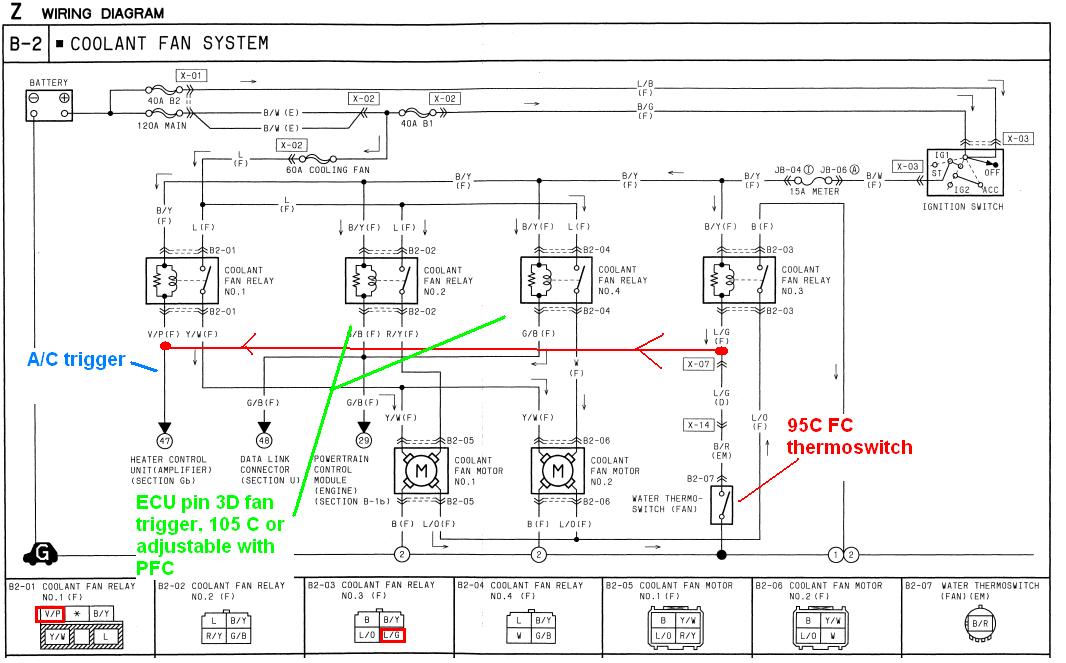
Looking at the diagram of the plug you can see that the #1 relay (A/C trigger) looks different than the other three relays. See page Z-40 of the 94 wiring diagram, which unfortunately does not include the cooling fan control module that Mazda added later. By splicing the thermoswitch trigger to the A/C trigger, you now have a 3 speed system with the A/C on and a 2 speed system without the A/C. A stock ECU + FC thermoswitch (no A/C) would run at medium fan speed when the thermoswitch comes on, then high fan speed at 105 C. A Power FC would run medium fan speed at your ECU trigger temp (adjustable in PFC Datalogit, most people choose 86-90 C). Then at 95 C you would run at full speed.
With the A/C on and a stock ECU, you would run at low speed with the A/C switched on, medium speed at 95 C (with FC thermoswitch) and high speed at 105 C (stock ECU fan trigger). With a Power FC and A/C, you would run at low speed with the A/C switched on, medium speed at whatever trigger temp is set in the Datalogit, and high speed at 95 C (thermoswitch temp).
Anyway, somebody just needs to test this. It's not that hard, just jumper one wire. Also the cooling fan control module should kick your fans on if it's been running at 95 C for a couple minutes before shutdown. But I haven't seen a full diagram of the fan control module's logic, so I can't be sure what conditions it uses. My buddy's FD has blown turbos so we're not doing much on it right now until it goes single.
Remember:
Relays 2 & 4 are connected to the ECU. They bump up the speed by one level.
Relay #1 is the A/C trigger. This relay bumps the fan speed up one level.
Relay #3 is connected to the thermoswitch. This relay bumps the fan speed up one level.
You can see how all sorts of control logic combinations are possible with this design. The Rx-8's have the fan relays controlled by the ECU based on vehicle speed and other such constraints. You can reflash the Rx-8 ECU to control it however you want. The low speed trigger temp is 98 C on that car, the high speed trigger temp is 108 C (same as FD thermoswitch), and of course there's an A/C trigger.
12-03-09, 06:55 PM
#12
FYI, the Rx-8 fan control system:
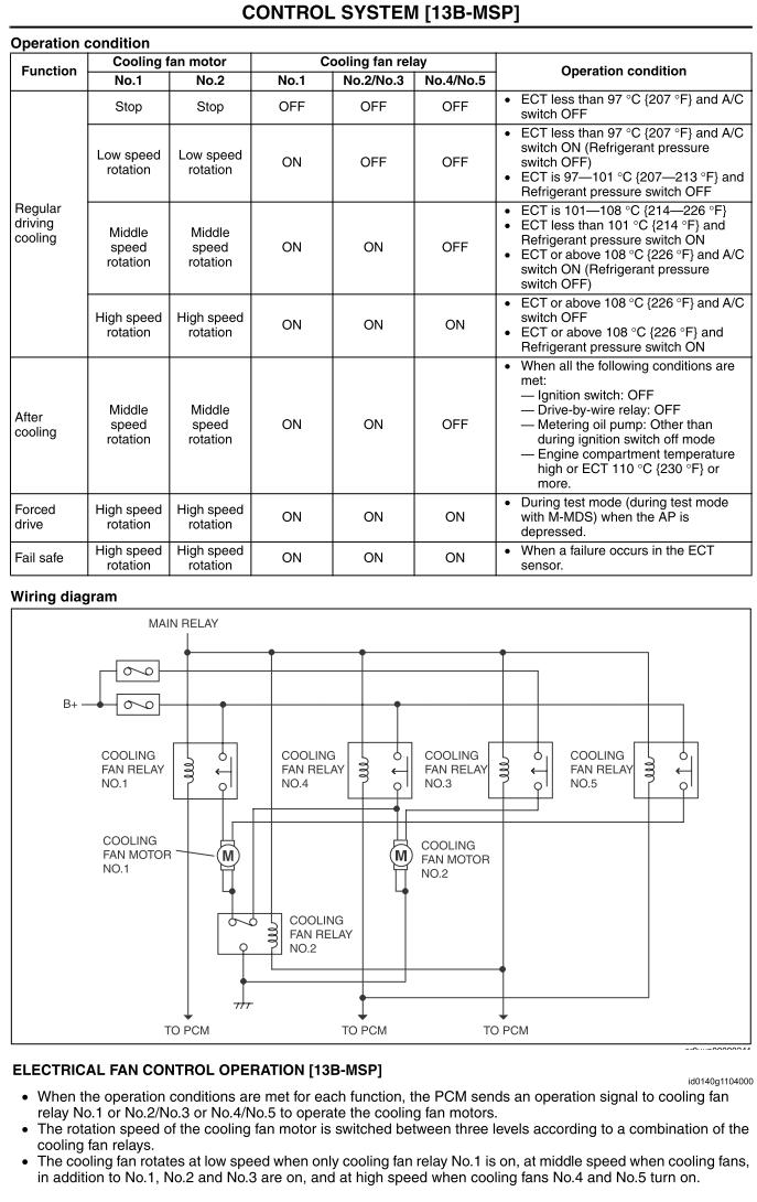
hmm. maybe I should make a dedicated thread that explains all this. Cooling fan control systems are interesting. There are a lot of different designs across manufacturers... some use resistors, some switch wiring from series to parallel, etc. The FD and Rx-8 actually have some of the most complicated setups. Some newer cars actually duty control the fans instead of stepping the speeds up and down with a bunch of relays.
hmm. maybe I should make a dedicated thread that explains all this. Cooling fan control systems are interesting. There are a lot of different designs across manufacturers... some use resistors, some switch wiring from series to parallel, etc. The FD and Rx-8 actually have some of the most complicated setups. Some newer cars actually duty control the fans instead of stepping the speeds up and down with a bunch of relays.
 12-03-09, 07:31 PM
#14
[Future...
S1MPSONS: How do I ...?
Other Users / Arghx: Go find it yourself!]
12-03-09, 08:14 PM
#15
The Taurus fan moves something like 3500 CFM. It is extremely common among all the LS1 swap guys. Look over on the V8rx7forum for more info on how to hook it up. There are a lot of guys running these fans, they move a ton of air.
On a side note, I used the stock fans on my swap and have not had any issues with them.
On a side note, I used the stock fans on my swap and have not had any issues with them.
12-26-09, 01:23 AM
#16
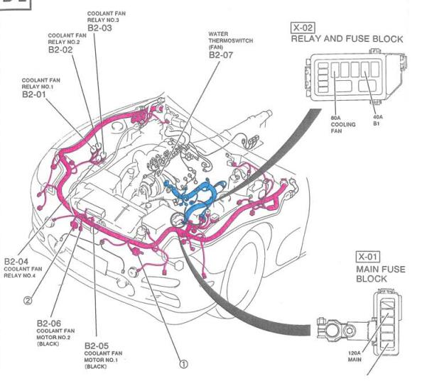
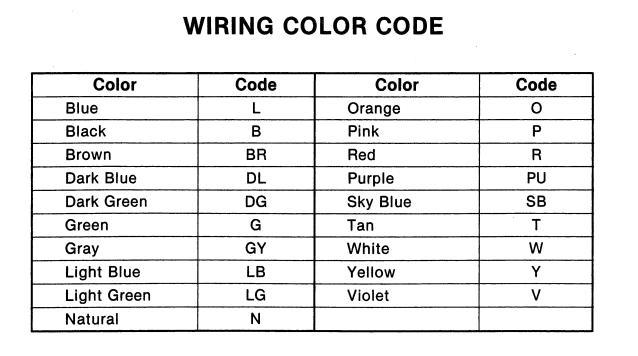
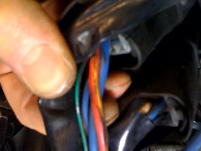
I found the A/C relay and the pink wire, no problem, but unfortunately none of my relays had the color scheme described for the thermoswitch relay #3. The picture below is the wires from the relay mounting in the #3 relay location. The manual shows there SHOULD be Black, Black & Yellow, Blue & Orange, and Blue & Green. I see Red & Yellow.
12-26-09, 02:40 AM
#17
Mazda did change the cooling fan wiring across model years (fan recall) so it's possible that the colors aren't going to match. It's probably still the same pin described in the connector diagram there though. You need to rig up a little bench tester to be sure.
Here's what I would do to verify this. Disconnect the relay. Locate the pin that SHOULD be +12V from the ignition circuit, labeled black/yellow. Make sure you orient the relay correctly to the diagram. The tab would be oriented upwards if you had the relay still plugged in.
Take two wires (at least a foot long) and crimp a spade on to each, a spade that will slide on to the terminals of the relay. They're probably normal radioshack size spades. Strip the other side of the wires. Put a spade to the terminal that SHOULD be +12V (pin for the black/yellow wire) on there and touch the stripped end to the positive side of a 12V battery. Do the same for the pin that SHOULD be light blue and green (the wire you wanted to tap in the first place), connecting that to the negative side of a 12V battery. You should hear the relay click, or if you don't hear it you will see continuity between the other two pins.
Does that make sense? You are just trying to make sure that only the wire colors have changed and nothing else is different on the circuit. If that test works, then there's a good chance everything is fine, because you know which two pins on the relay control the coil. The last step would be to plug the relay in and back probe the pin that SHOULD be black/yellow for +12V ignition power. So first you narrow down which two pins are for the coil. Then when you check for ignition power you will know which pin is for +12V and which is for ground. The ground pin is the one you want.
12-26-09, 05:07 PM
#19
The colors are practically irrelevant. Meter the relay and the harness to figure out which pin does which function. You want the pin that is hooked to the ground side of the coil on the relay, the same wire that geos to the thermoswitch. I already explained one way to do it. You might even be able to meter for continuity between the relay's pins and the thermoswitch itself. Or you can just tap off the thermoswitch directly if you are not comfortable messing with the #3 relay.
http://electronics.howstuffworks.com/relay1.htm
http://electronics.howstuffworks.com/relay1.htm
12-26-09, 06:08 PM
#20
The colors are practically irrelevant. Meter the relay and the harness to figure out which pin does which function. You want the pin that is hooked to the ground side of the coil on the relay, the same wire that geos to the thermoswitch. I already explained one way to do it. You might even be able to meter for continuity between the relay's pins and the thermoswitch itself. Or you can just tap off the thermoswitch directly if you are not comfortable messing with the #3 relay.
http://electronics.howstuffworks.com/relay1.htm
http://electronics.howstuffworks.com/relay1.htm
12-27-09, 01:56 AM
#21
the first time I tried to read a wiring diagram, I thought I was deciphering Egyptian hieroglyphs. Now I think I'm pretty good compared to the average home mechanic, but we all have to start somewhere. So don't be intimidated by electrical stuff. Download the wiring diagrams from the sticky thread and read through the first 20 pages or so, it explains a decent amount of stuff.
