When you click on links to various merchants on this site and make a purchase, this can result in this site earning a commission. Affiliate programs and affiliations include, but are not limited to, the eBay Partner Network.
^ I am going to post up pics of the install once I finish up the work. No big issues with doing the retrofit, although I did alter the mod a bit by keeping/using the retaining rings on the back of the gauges. So, instead of having a bunch of tabs cut into the the black plastic cover, I used a dremel to slowly remove layers of the material that would form the tabs so I ended up with a smooth circle into which I pressed in the gauges. I then screwed on the retaining rings so the gauges fit snuggly into the holes. This worked for all the gauges except the tach as the size of the tach made using the retaining ring impossible. So, for the tach, I still did the cut method described above, but made sure I left the hole small enough so the tach pressed snugly into place. Seems to work just like the tab method.
One issue I note - this is why I asked the question about using the inner black front press in ring - is the gauges don't quite exactly position into the front plastic lens cover. On the tach and the oil pressure gauge, they are slightly off centered with the lens cover. So you see a bit of the inner black press ring thru the lens cover. I have yet tried to then fit this into the cluster gauge shroud so it might not even be an issue at all. Frankly, I doubt anyone would notice but I am pretty **** about this stuff. Since I didn't hear from anyone on the forum about whether they used inner ring - without it the install is super clean - I contacted SpeedHut and they confirm you need to ring to 1) hold the gauge faces from wobbling against the needles, and 2) to keep light from escaping around the outer edge of the ring. So, I'll keep this with as part of the conversion and live with the bit of black plastic you might see.
If you have some patience and ability, you can do the conversion yourself. The directions posted in this thread are really good and I'll add my method and pics soon for those that want to go that route. If you want someone else to do the conversion for you, contact Toby at Broadfield Customs: Phone:(309)-261-4827Email:Toby@BroadfieldCustoms.comWebsite:www.broadfieldcustoms.com
He has a ton of pics of FD conversions he's done on the "other" forum (the one without any pistons as a hint) or on his website and he's remarkably inexpensive to use (around $200-300 for the conversion). He also offers a 10% discount on SpeedHut guages if you order thru him and he ups that to 15% if he does the conversion work for you. The only caveat to this is he doesn't do the conversion like shown in this thread so check his pics closely. He also requires you to use the Legacy style bezels (you can order these for the Revolution gauges) so I did this in case I couldn't complete the conversion. You don't use them anyway for your own conversion so this should not be a big deal.
Everything mentioned above about broadfield is correct, but the labor cost is actually $350 (just got a quote from him). He currently also has a 10-12 week lead time these modifications. Great guy though and def willing to help and answer questions.
I was giving Toby serious consideration as the price isnt too bad. I could hammer out the whole rest of the interior while waiting for the gauges. That's a long time no drive the 7 though. The gauges definitely need to be done though as I have no reliable tach or speedo. Well, the tach works on my commander, but no speed.
Anyone got a full writeup or step-by-step (with pics) for an FD? This thread is great but it would be awesome if all the info was consolidated into a good guide
Not a detailed writeup as I have little time nowadays, but a few observations I hope will be helpful. Just completed my install of the SpeedHut gauges:
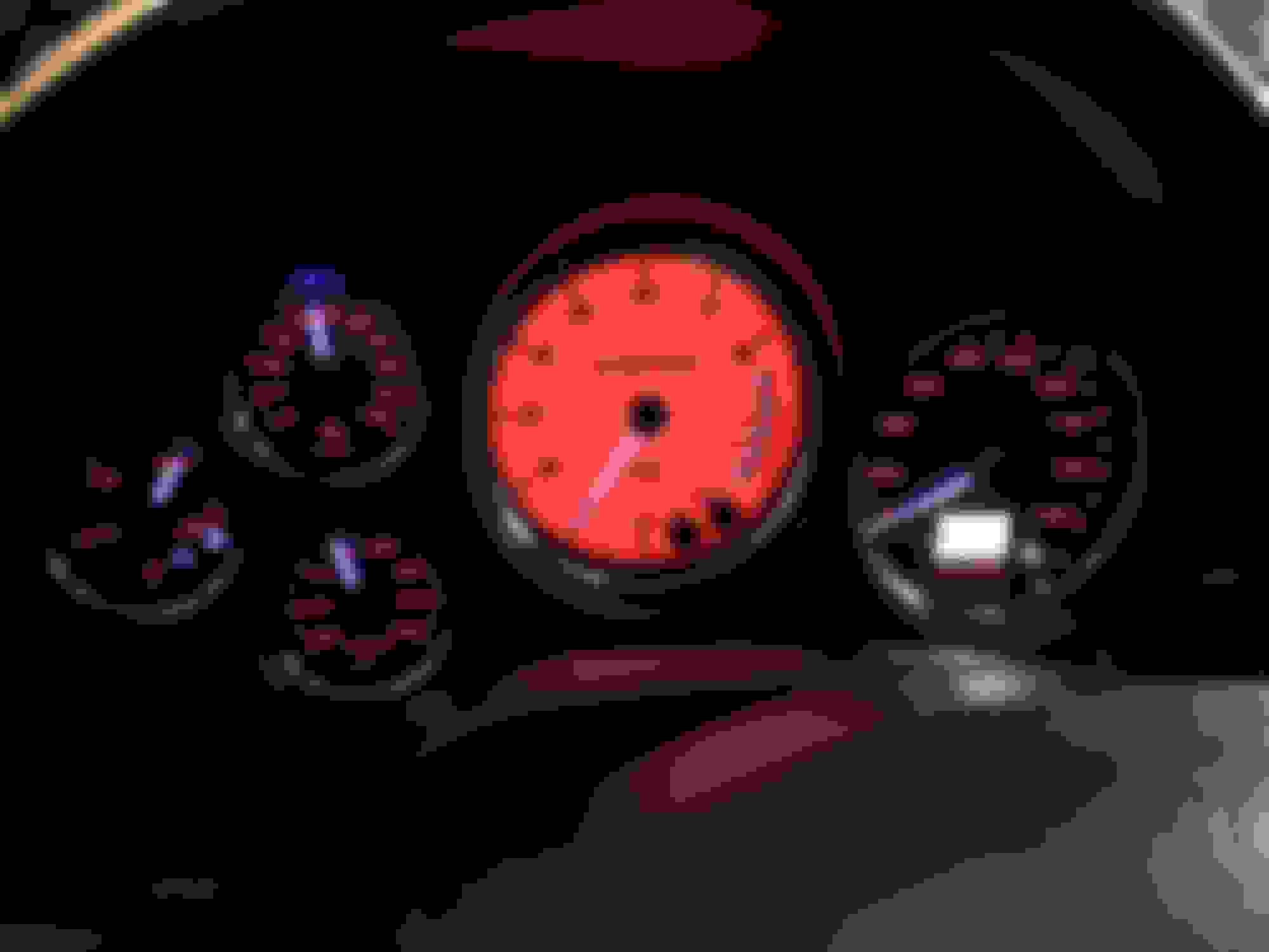
Really like the look of the gauges. Went with a red tachometer as it reflects the red bits I've added to the car. Also went with red numbers to accent the effect and had the gauge needles done in white that turn blue at night for a more modern effect. The options with the gauges are almost unlimited, so you can do whatever you like best.
First, the OP previous write up is super helpful in doing the conversion and I appreciate the time the OP took to put the info together. Fitting the gauges into the instrument cluster is the most difficult part of the conversion. The instructions provided by SpeedHut on installing the gauge sensors are nicely detailed and SpeedHut technical support is really good so feel free to call them like I did about 1/2 dozen times. Wiring these up is also not too bad. I used a ground source in the driver's footwell and tied in the two grounds needed for the units into one wire. I tied into a "ignition on" source under the steering wheel for power (you can find any keyed on power source for this by using a multimeter) and tapped into the stock instrument cluster lighting source on one of the plugs on the back of the cluster. Used the FD wiring diagrams to find this source and tested it with a multimeter by turning on the cluster lights and measuring for a 12 volt output. Finally, since I have the GPS-based speedo, I used the SpeedHut suggestion to connect a power source directly to the battery so the speedo has an instant on capability. I also placed the GPS "antenna" in the middle of the dash, all the way up front by the windshield (used two-way tape to affix it to the dash between the two vents).
Couple of observations. First, the gauge sizes are NOT a direct fit into the FD instrument cluster as suggested by the OP. I might be too ****, but based on what was previously posted, I expected that the openings in the black plastic cover (the conversion in which the OP made a number of cuts into so he could insert the gauges into it) to match the sizes of the gauges. They do not exactly match, resulting in some of the inner black gauge rings to be exposed behind the OEM chrome rings, primarily on the tachometer and the speedo. So, once I saw this was a problem, I abandoned the OP's original method of inserting the gauges thru a series of cuts into the black surround, and instead, used my Dremel to enlarge each gauge hole in the black plastic. So, where the OP shows the series of cuts he did, I dremeled these tabs off to result in an enlarged hole for each gauge. I did this slowly, repeatedly trying to insert in the gauge to check for fitment and to better position each gauge behind the chrome cover piece. For example, when using the OP method of cutting tabs into the tach hole, this resulted in the tach being positioned too low in the cluster so, when I attached the chrome cover, you could see the upper portion of the SpeedHut gauge inner black ring (the ring is shown by the OP and is the piece he used to mark spots in the chrome and clear plastic cover, where he then drilled small holes into the clear plastic cover) intruding into the inside of the tach chrome ring. So, I slowly used the Dremel to remove more of the upper portion of the black plastic cover so I could reposition the tach gauge to better fit into the hole and in the chrome clear plastic cover. The result of this process, which took some time, is the gauges are now better positioned within the FD cluster, A second benefit is I ended up being able to use the SpeedHut tightening rings to affix the gauges on the black plastic cover. Again, this does take some patience and more material needs to be removed than what is shown in the OP posts, but I think you end up with better centered gauges. I used this method on 4 out of the 5 gauges and found the oil pressure gauge is the only one that seemed to fit perfectly within the original FD instrument cluster hole.
Second, if you do this conversion, you need to think thru the wiring from a disconnect perspective. What I mean by this is some of the SpeedHut wiring doesn't come with quick disconnects. So, if you hard wire the gauges into your electrical system, and if you ever need to remove the cluster, you'll have to cut the wiring and re-solder when re-installing the cluster. I didn't want to do this, so I took the time to add in quick disconnects on all the wiring as well as labels I added to each side of the wiring connect so if I ever take the cluster out, I can easily do this and reconnect based on the labeling. I highly recommend you do this as well. One note on connections - if you use the GPS speedo unit, then I recommend you add a GPS cable extender such as this:
This extender will allow you to quick disconnect the speedo wiring. Without it, you'll have to take apart the cluster to gain access to removing the cable. A second benefit to doing this is the extender I listed has a 90 degree bend in it, making the cabling fit better into the FD cluster.
Third, the gauge kit comes with an inverter to backlight the gauges. The instructions call for one inverter to be used for all of the gauges but the problem with this, is as you connect each gauge to the inverter, then the lighting power supplied to each gauge is reduced. So, be aware, based on the color of the gauge lighting you select, one inverter may not make your backlighting bright enough to be seen at night. For my gauges, to get them to the brightness level you see in the pic, I ended up using 3 inverters, with for powering the speedo, one for the tach, and one for the remaining 3 smaller gauges. SpeedHut says my issue is directly related to me using a red background tach with red numbers on the other gauges, and the color red takes a lot of power, hence the need for more than one inverter. It's not a big issue but I spent some time trying to diagnose the problem before stumbling on what was happening with the lighting. I ended up wiring the 3 inverters together and then splicing them to one dimmer versus using 3 separate dimmers.
Based on the above, the best lighting option for the gauges based on brightness would be ones with a black background and white numbering as this is the easiest to power with an inverter. So, go with this option if you are concerned about backlighting or do as I did and plan on using more than one inverter.
Finally, I learned from SpeedHut that once you take apart the gauges, you technically void the warranty. So, when doing this conversion, when you remove the chrome cover and glass of the gauges, this voids the warranty. Remember to set these pieces aside so you can put them back on the gauges if you need to send them back in for servicing.
Hope this helps others and good luck!
Last edited by David Hayes; Oct 24, 2018 at 04:14 PM.
Do the original images in the OP post still appear for everyone? I cannot seem to view them, and would be great to get some more visual reference on this install. I'm looking to just replace one gauge in the cluster with SH, namely the factory oil pressure gauge with a SH oil temp gauge.
Without pics it is difficult to tell apart the two methods that are discussed in this thread.
Is it correct that the OP method tries to do this with no cutting of the factory black plastic bezel?
^ Yes I can see all of the pics, and no, you are not correct about the cutting of the black plastic bezel for the factory oil pressure gauge. With either method, the original OP way or what I describe, you have to trim some of the black plastic bezel. Here is a pic of what the OP did:
He cut lines into the black plastic bezel and then bent them slowly back to form tabs. He then insert the SpeedHut gauge into the hole and used the tabs to secure the gauge into place. So, if you follow this way of installing the gauges, you need to do some cutting of the black plastic.
What I tried to describe with this method is the resulting hole won't completely line up with the clear plastic, chrome ring cover you will install over the black plastic bezel. So, what I did was slowly trim out the black plastic (essentially cutting off the tabs in the above pic) and then trimming the remaining circle to better position the SpeedHut gauge behind the clear plastic, chrome ring cover. What I suggest is you follow the original OP's instructions and see if you are okay with the placement of the new SpeedHut gauge. If so, no problems. If not, and you want the gauge to be better positioned, then follow what I did to better center the gauge behind the chrome ring. If I remember correctly, and assuming you use the factory oil pressure gauge location for your new SpeedHut oil temp gauge, you will need to trim the opening so the gauge will slide slightly up and to the left.
Thanks David, yes that makes perfect sense! I am going to try viewing the thread again from a different connection, hopefully I can see more photos that way. And then I will re-read the instructions... a couple dozen times. I am in a pretty lucky position as I have a spare cluster to muck about with, so I have at least two attempts to get it right.
Your assumption is right, that my idea is to remove the factory oil pressure gauge, and in its same place, mount the SH oil temp gauge. I have oil pres and afr on the pillar, so the factory oil pres is currently doing nothing.
If I understand your point, you essentially reshape the opening so as to "move" the opening upwards and to the left, in order to best line up the SH gauge with the factory clear lens/chrome ring plate. I suppose in either process, the SH ring/bezel is discarded? I think that's what I got from the descriptions so far.
^ Happy to help. Yes, you are correct about "moving" the hole for the gauge up and to the left. Check this first to ensure that is the way it works on your cluster as I'd guess there will be variations from car to car. And yes, you don't use the SH ring/bezel/glass, but keep it in case you need to send the gauge in for repair. In theory, if you unscrew the ring/bezel from the gauge, you void the warranty, so you'd need to send in the complete gauge for repairs.
I too had an extra cluster to practice on which is good, because I destroyed the chrome/clear plastic cover trying to drill holes into I for my SH calibration buttons. Found out you need firmly secure the plastic to a solid base before drilling.
Let me know if I can answer any other questions.
Last edited by David Hayes; Nov 8, 2018 at 05:06 PM.
Nice. So I just realized if I was only going to do the oil pressure gauge, i would need to cut up the light distributing lens assembly since the coolant temp and oil pres share the same molded part. I have the factory coolant temp gauge working with the LS (mazda sender into GM block, I think with an adapter?) but it's a bit of a guessing game as to what the exact temperature is. Maybe I oughta go for the SH coolant temp as well... hmmm.
Hoping SH will have another black friday sale this year. If/when I do this I'll be sure to take some pics and hopefully complement the existing great info.
^ That is true about the two gauges sharing the assembly. While cutting it apart is not that big of a deal, the resulting light output might vary for water temp gauge. I vote for you replacing all of the gauges! The SH water temp unit is very nice and it gives me a reliable temp reading - matches what I see on the Haltech.
I dont think that particualr adapater will work as I believe the speedhut Sensor has a longer probe. But it gives me a starting point. This is the sensor near the oil filter right? If So just need to find a 1/8bpst adapter to fit
Ace Harware may also be your friend. They have a bunch of adapters in the plumbing section and one might work. I have my SH water temp sensor installed into the back of my coolant filler assembly and as I recall, got an adapter from them.
Last edited by David Hayes; Nov 9, 2018 at 01:02 PM.
That should work great thank you for the link! I have debated just putting it in the housing but with the gauges setup the stock location will be unused anyhow.
If you do get that last piece, the FRS/BRZ adapter, just check to see if it comes with a plug for the female BPST port. Otherwise you will have an open port left on the adapter. (It is designed for the FRS specifically and that is where the factory FRS sender would go into)
It comes with the plug for the extra NPT port, for sure.. but also for the BPST one? (Description seems to show there are a total of 4 openings) Just making sure there's no surprises is all.
Not a detailed writeup as I have little time nowadays, but a few observations I hope will be helpful. Just completed my install of the SpeedHut gauges:
Really like the look of the gauges. Went with a red tachometer as it reflects the red bits I've added to the car. Also went with red numbers to accent the effect and had the gauge needles done in white that turn blue at night for a more modern effect. The options with the gauges are almost unlimited, so you can do whatever you like best.
First, the OP previous write up is super helpful in doing the conversion and I appreciate the time the OP took to put the info together. Fitting the gauges into the instrument cluster is the most difficult part of the conversion. The instructions provided by SpeedHut on installing the gauge sensors are nicely detailed and SpeedHut technical support is really good so feel free to call them like I did about 1/2 dozen times. Wiring these up is also not too bad. I used a ground source in the driver's footwell and tied in the two grounds needed for the units into one wire. I tied into a "ignition on" source under the steering wheel for power (you can find any keyed on power source for this by using a multimeter) and tapped into the stock instrument cluster lighting source on one of the plugs on the back of the cluster. Used the FD wiring diagrams to find this source and tested it with a multimeter by turning on the cluster lights and measuring for a 12 volt output. Finally, since I have the GPS-based speedo, I used the SpeedHut suggestion to connect a power source directly to the battery so the speedo has an instant on capability. I also placed the GPS "antenna" in the middle of the dash, all the way up front by the windshield (used two-way tape to affix it to the dash between the two vents).
Couple of observations. First, the gauge sizes are NOT a direct fit into the FD instrument cluster as suggested by the OP. I might be too ****, but based on what was previously posted, I expected that the openings in the black plastic cover (the conversion in which the OP made a number of cuts into so he could insert the gauges into it) to match the sizes of the gauges. They do not exactly match, resulting in some of the inner black gauge rings to be exposed behind the OEM chrome rings, primarily on the tachometer and the speedo. So, once I saw this was a problem, I abandoned the OP's original method of inserting the gauges thru a series of cuts into the black surround, and instead, used my Dremel to enlarge each gauge hole in the black plastic. So, where the OP shows the series of cuts he did, I dremeled these tabs off to result in an enlarged hole for each gauge. I did this slowly, repeatedly trying to insert in the gauge to check for fitment and to better position each gauge behind the chrome cover piece. For example, when using the OP method of cutting tabs into the tach hole, this resulted in the tach being positioned too low in the cluster so, when I attached the chrome cover, you could see the upper portion of the SpeedHut gauge inner black ring (the ring is shown by the OP and is the piece he used to mark spots in the chrome and clear plastic cover, where he then drilled small holes into the clear plastic cover) intruding into the inside of the tach chrome ring. So, I slowly used the Dremel to remove more of the upper portion of the black plastic cover so I could reposition the tach gauge to better fit into the hole and in the chrome clear plastic cover. The result of this process, which took some time, is the gauges are now better positioned within the FD cluster, A second benefit is I ended up being able to use the SpeedHut tightening rings to affix the gauges on the black plastic cover. Again, this does take some patience and more material needs to be removed than what is shown in the OP posts, but I think you end up with better centered gauges. I used this method on 4 out of the 5 gauges and found the oil pressure gauge is the only one that seemed to fit perfectly within the original FD instrument cluster hole.
Second, if you do this conversion, you need to think thru the wiring from a disconnect perspective. What I mean by this is some of the SpeedHut wiring doesn't come with quick disconnects. So, if you hard wire the gauges into your electrical system, and if you ever need to remove the cluster, you'll have to cut the wiring and re-solder when re-installing the cluster. I didn't want to do this, so I took the time to add in quick disconnects on all the wiring as well as labels I added to each side of the wiring connect so if I ever take the cluster out, I can easily do this and reconnect based on the labeling. I highly recommend you do this as well. One note on connections - if you use the GPS speedo unit, then I recommend you add a GPS cable extender such as this:
This extender will allow you to quick disconnect the speedo wiring. Without it, you'll have to take apart the cluster to gain access to removing the cable. A second benefit to doing this is the extender I listed has a 90 degree bend in it, making the cabling fit better into the FD cluster.
Third, the gauge kit comes with an inverter to backlight the gauges. The instructions call for one inverter to be used for all of the gauges but the problem with this, is as you connect each gauge to the inverter, then the lighting power supplied to each gauge is reduced. So, be aware, based on the color of the gauge lighting you select, one inverter may not make your backlighting bright enough to be seen at night. For my gauges, to get them to the brightness level you see in the pic, I ended up using 3 inverters, with for powering the speedo, one for the tach, and one for the remaining 3 smaller gauges. SpeedHut says my issue is directly related to me using a red background tach with red numbers on the other gauges, and the color red takes a lot of power, hence the need for more than one inverter. It's not a big issue but I spent some time trying to diagnose the problem before stumbling on what was happening with the lighting. I ended up wiring the 3 inverters together and then splicing them to one dimmer versus using 3 separate dimmers.
Based on the above, the best lighting option for the gauges based on brightness would be ones with a black background and white numbering as this is the easiest to power with an inverter. So, go with this option if you are concerned about backlighting or do as I did and plan on using more than one inverter.
Finally, I learned from SpeedHut that once you take apart the gauges, you technically void the warranty. So, when doing this conversion, when you remove the chrome cover and glass of the gauges, this voids the warranty. Remember to set these pieces aside so you can put them back on the gauges if you need to send them back in for servicing.
Hope this helps others and good luck!
That may well be the single mod left that would have made your car a little more badass than it already was!!! well done my friend!!
cant wait to see it in person again in May!!


 The SH water temp unit is very nice and it gives me a reliable temp reading - matches what I see on the Haltech.
