When you click on links to various merchants on this site and make a purchase, this can result in this site earning a commission. Affiliate programs and affiliations include, but are not limited to, the eBay Partner Network.
I have seen something similar. It looks like some components on the Speedometer circuit board are damaged. Follow the steps to remove the instrument cluster. Examine the Speedometer circuit board for leaked capacitors (there may be several leaked) and damage to other components from the leaked acid.
This thread has excellent advice to repair the speedo. Study it along with another thread, Troubleshooting the FD Speedometer thread. I encourage use of the Troubleshooting thread to document your progress.
Bear in mind, there are no schematics to reference any repair of this board. A sharp eye during a visual inspection along with photos of any potential problems is critical to ensure a repair is made.
I was going to ask if your cluster was a 99+ spec JDM cluster then recommend adding the grounds. Looks like your problem was solved!
Is there a thread where a 99 spec cluster kph can be converted to the current USA mph/m on the speedometer and on the odo? I'd like to do that before I install my 99 spec. It has a boost gauge as well.
MW
I have bad times with my odometer.
it stopped showing numbers recently. I changed the C3 1000uF that showed signs of leak and it worked again. Then it stopped working again. At that point I noticed that if I remove the negative of the battery for a night, the numbers show up again next morning. But they disappear while driving and dont come again until I remove the n�gative again for a night.
And now even that trick doesn't work.
So I removed my cluster again and changed again C3 1000uF and Also C1 10uF. It still doesn't work.
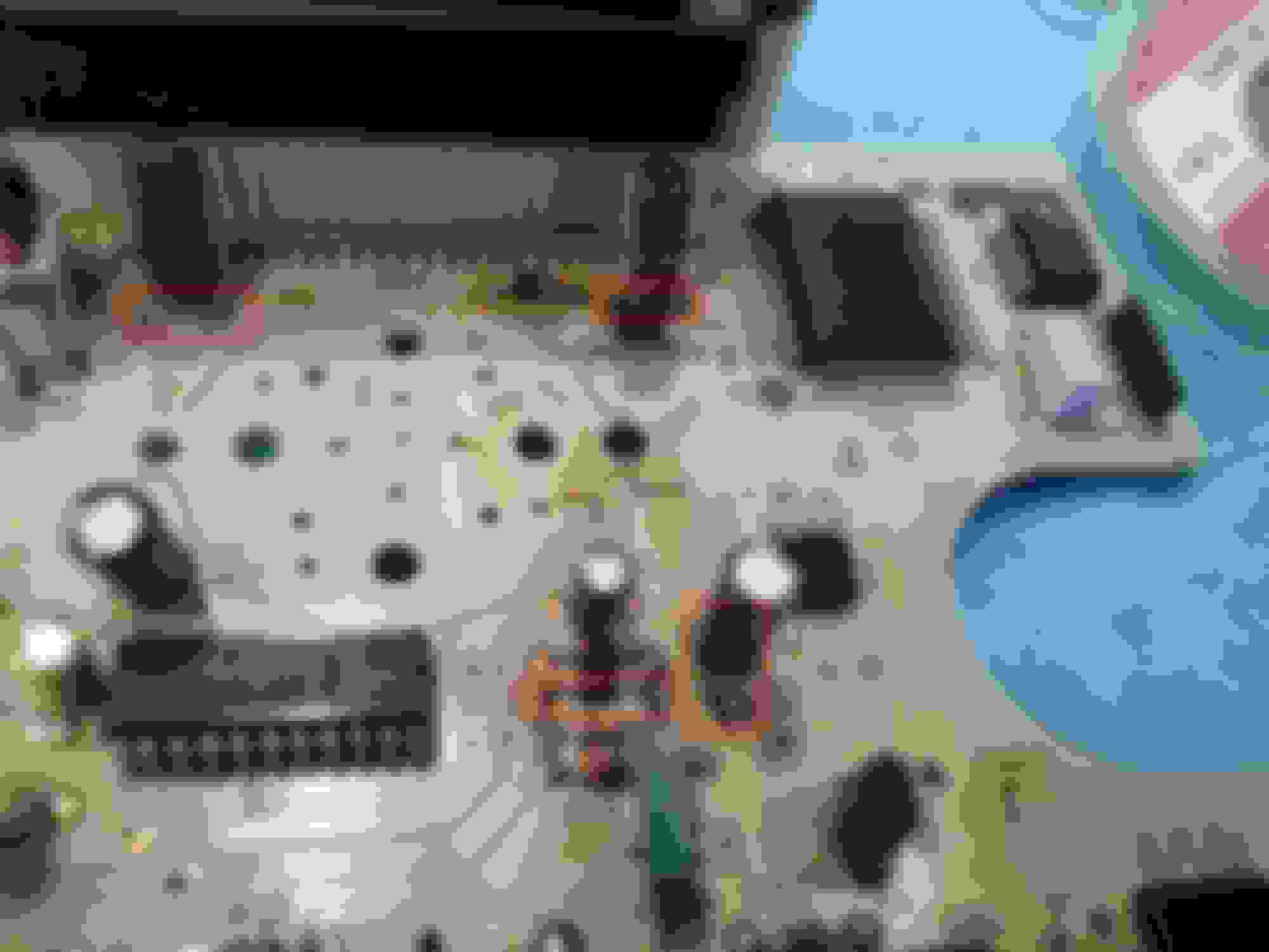
Before changing other parts I want TO share pictures with you. All caps look in good shape but maybe I miss something. Only DA1 has one leg that looks burnt, or maybe its from the previous leak of Old C3. Anyway is DA1 an odometer involved component?
Here are pics. Please give me your comments/advice.
I have bad times with my odometer.
it stopped showing numbers recently. I changed the C3 1000uF that showed signs of leak and it worked again. Then it stopped working again. At that point I noticed that if I remove the negative of the battery for a night, the numbers show up again next morning. But they disappear while driving and dont come again until I remove the n�gative again for a night.
And now even that trick doesn't work.
So I removed my cluster again and changed again C3 1000uF and Also C1 10uF. It still doesn't work.
Before changing other parts I want TO share pictures with you. All caps look in good shape but maybe I miss something. Only DA1 has one leg that looks burnt, or maybe its from the previous leak of Old C3. Anyway is DA1 an odometer involved component?
Here are pics. Please give me your comments/advice.
replace the ZD5 and other 2 zenner diodes right next to it. I also would replace and clean the DA1 part. I had to replace a few zenner diodes in mine and those contacts look dirty and burnt a little on your picture
I would advise not to replace the Zener diodes. They are fairly stout solid state components. I would strongly recommend to clean the areas with isopropyl alcohol. That will neutralize any acid that still remains from the capacitor leaks. I can see plenty of leakage too. Based upon the photos submitted, I recommend replacing certain capacitors, some of them may be replaced for a 2nd (or 3rd) time. I also see a lot of broken/cold solder joints, especially around ZD5, ZD4, and ZD7. The acid was the major culprit to those solder joints.
Here are my recommendations based upon the photos (see red highlighs):
TR6 has a bad solder joint. Suspect all 3 joints are bad - recommend replace solder. There is a 2nd bad solder joint at ZD8 anode - recommend replace solder. Solder joint for C3 looks too excessive. Need a better angle. I would suggest replacing this capacitor again. It also needs just a bit more clearance off of the board. Clean area around C3 & DA1 with alcohol. Replace C6, it also has a bad solder joint. This capacitor appears to have a bulged top, which is a bad sign.
Recommend replace C11 and C12. These caps also appear to have bulged tops. This is a better view of ZD8. Note the missing solder on the anode (left) side. Solder needs to fill the cup from the backside of the board to the top. C1 has excessive solder. Clean the board around C1 too. There appears to be charring around that one leg, which could mean the eyelet is damaged. Use a DMM to read the trace from C1 anode (C1 +) to ZD3 cathode (ZD3 -). It should read 0 ohms.
This is a better angle to show C6 has a bad solder joint. It also has a bulged top. C4 appears to be bad as well. Replace these bad capacitors.
Clean up the areas around C3, TR7, DA1, and ZD4, ZD7, and ZD4 with isopropyl alcohol. Recommend replacing solder on ZD4, ZD5, and ZD7. Replace solder on the ground plane first then replace the solder on the opposite ends of these diodes. This is a different angle that shows C4 and C6 with bad solder joints. Just replace these 2 capacitors.
I highly encourage you to check out another thread that I have which discusses some soldering tips & tricks. It should make soldering and de-soldering an easier task for a DIY project. Just remember, it will not make you an expert!
Glad to lend a hand. Copy, 94 JDM cluster is giving you problems. Let me know if you need more help identifying bad components. Don't forget to take pictures and ask for help when you are stuck. Best of luck on your repairs!
Also have HOLD light flashing most of the time, and have the check engine light flashing as soon as there is any moderate acceleration.
the Check engine code gives a different diagnosis than the hold code. Attempted solution replacing speed sensor (based on reading the error blinking code), same lack of a good result.
Also seem to have very intermittent Bose radio system, that somebody mentioned was also a capacitor problem, but with no details that I saw on fixing the radio.
Long long threads to try to digest here.
Complication is that the local speedometer shop that used to work on such things as the odometer will not work on this problem because he says he cannot get parts any more.
Any latest good 2020 advice, or thread entries to focus upon?
Have you replaced the capacitor(s) outlined in this thread? We can take this conversation to my speedometer troubleshooting thread (refer to post #304 for link) to take a deeper dive into your specific problems with the speedometer. Do you have any recent speedo board photos to share?
As I recall, you had similar problems with the trans (HOLD light flashing) around Nov 2018. Did that problem go away but then resurface? I'd also ask to see photos of your instrument cluster flex print. It would have to be removed because components are hidden behind the layer you normally see. Some components on the flex print do interact with the shift lights on the tach.
Please refresh my memory, how are your solder skills? Do you want to fix these problems yourself or you looking for someone to make the repairs?
The Bose stereo is a separate issue. For now, let's focus on your speedo and/or trans problem.
Pardon the slow response; got detoured to other non car stuff.
The old problem has endured, except for after one trip to the mechanic to change out a speed sensor, it worked for a day before going back to the usual malfunction.
I have not pulled the instrument cluster, so do not have any pictures. I am a bit leary of trying to pull the cluster myself because of some postings of people breaking things when they try to pull the cluster. Local Mazda dealer shop will pull it for me, but I am having trouble finding anybody who knows what to do with it, AND can find any parts for it.
I have soldered stuff, mostly years ago, but would rather have the work done by someone with skill and equipment for temperature sensitive components on double sided boards with electrolyte leakage messes.
One question is whether the odometer and shift hold light and check engine light are likely one cause cascading, or a problem with multiple components causing each symptom. If I Pull the panel and have it worked on, it would be good to fix all the problems at once before putting it back together.
If the cluster should happen to get damaged worse, finding a new one set up for an auto transmission might be tough. ( it took 3 months to find a new rear hatch window!)
The car is looking beautiful with a new paint job, so it would be nice to fix some of these other problems.
Cheers.
Thanks for the update. I suspect there are many unrelated issues. The blank odo is definitely a problem in your speedo board. The only way to investigate the extent of the damage is to remove the cluster and inspect the speedo board. Your CEL code can be checked by placing a jumper wire between TEN and GND on the diagnostic port. The CEL codes are found in the FSM, Pg F-22 through F-25. Refer to Pg F-21 in the FSM to count the sequence of CEL flashes.
Did you know that you can check the stored codes from your transmission? That is why the HOLD light flashes. It will flash in the same manner as the CEL. Follow the instructions in the FSM, Pg K-214. The diagnostic trouble code number chart is found on Pg K-217. Basically, you insert a jumper pin between TAT and GND on the diagnostic port. Turn the ignition to the ON position (engine not started/running) then count the flashes.
To answer your question about the speedo board, it is the same for all FDs. They can be obtained. The only difference between the versions is the placement of 2 resistors on the back side of the board. These 2 resistors will configure the speedo for km/auto trans, km/manual trans, mi/auto trans, mi/manual trans. You could even use a JDM speedo board and swap in a USDM face plate with a minor modification to the board.
Let's take a look at your CEL and HOLD light trouble codes then go from there. I can understand your reservation for removing the instrument cluster. If you want the odo to come back then the cluster and hood will have to be removed. I have pulled my hood on/off several times and thankfully, *knock on wood* well...I don't want to jinks myself. If you follow the recommendations in this thread then you shouldn't have a problem removing the cluster and hood. As a tip, you can loosen the support bolts for the steering column to gain more clearance when removing the hood. Just make sure you torque those bolts to the factory spec when reinstalling everything!
way back in post 323, from 2018,
Hold light flashes and shows a 7 code, which seem to eventually prompt a check engine light with a 6 code, and eventually the check engine chirper beep. Code 7 says it is the speed sensor. The AT computer has been replaced with the rev B part.
@rousu, could you please verify those 2 codes are still present? I did more digging into your problem and I suspect that your speedo board is the critical failure point for all 3 problems. I missed your initial posting of the trans code and CEL code, so thanks for bringing that bit of info back into light! That missing info was a big clue.
Once you confirm the CEL code and auto trans code, I'd like to you take a look at the FSM, Pg F-29. Specifically, this page is the troubleshooting chart for a CEL code 6, "Vehicle Speed Sensor".
Step 1 asks, "Is speedometer working correctly?" If YES then go to next step otherwise, go to Step 5.
Let's assume that your speedo is working properly. Read the next step:
Step 2 asks, "Check for PCMT trouble code, is code No. 7 also present?" If YES then go to Step 5 otherwise, go to next step.
Step 5 will have you remove the speed sensor for further testing. According to your information from 2018, you have both CEL Code 6 and Trans Code 7. That would confirm both codes are related! Now, take a look at the circuit diagram below the troubleshooting chart. It shows the Vehicle Speed Sensor, a combination meter, PCME (ECU), and a branch to the PCMT (AT-ECU). See that part in the middle - Combination Meter? That is your speedometer circuit board! Specifically, Pins 3A, 3C, and 3E belong to the instrument cluster connector that feed signals to the speedo board.
With this new information available, I recommend removal of the instrument cluster, measure the wire resistance and voltage for the Vehicle Speed Sensor (VSS).
Please follow the proper procedures for testing resistance and voltage for that sensor. When testing the VSS for voltage, use the AC volts setting. While the cluster is removed from the car then you should inspect the speedo board per this thread's recommendations. I also curate a couple of other threads so if this thread doesn't fully recover your speedo then we can jump down the rabbit hole in the other thread. I would bet dimes to donuts that your VSS is fine. However, your speedo board may need some capacitors replaced and/or other damaged components replaced.
The benefit of repairing your current speedo board is that you still retain the mileage without any issues and the speedo retains its speed calibration. The downside of this route - it could take several repairs to get the board working properly. There are a few companies that offer a repair service but you need to ask about warranty work and how they check the board. Do they check the full function or just verify the speedo needle reads a calibrated speed? The benefit of replacing your speedo board with a new unit is that the problem(s) is/are fixed. The downside to that route - your odo is 0 (unless you swap chips), you may have to report the odo replacement to the DMV, you don't know what components were damaged, and you have new old stock components that may still fail in the near future because of component age.
Might be helpful. More history: the speed sensors have been replaced with replacement ones, and the problem remained. This strongly suggests the problem is not in the sensors.
The local firm recommended for pulling the cluster and repairing it was Tacoma Speedometer, but they said it was too old for them to work on.
Other leads have not been checked out.
Even though your speed sensors were replaced, it is still a good idea to verify the wiring going to them are functional. The vehicle speed sensor that is used by the speedometer is on the transmission. Was that sensor previously replaced? There are speed sensors at the wheels but they are only used for ABS. What other leads have you checked? Have you verified the same CEL and A/T codes are still present?
You may find a couple of shops that can work on the speedo board whom are not local to you. That means you have to remove the instrument cluster on your own then send it to them. I believe there is a place in Florida that works on them. The shop name escapes me though.
Should you choose that route then remove the speedo board, take several photos of it at various up-close angles, then post it here for further analysis before the instrument cluster (speedo board) is sent out for repair.
The other option would be to repair the board yourself using this thread and/or other related threads. You could alternatively find a local company who repairs circuit boards. You would only use their solder services to replace suspect components. You would have to do the initial diagnosis and final testing once components are replaced. Bear in mind, this repair may take several attempts to fix all the bad components.
I am evaluating options. Atkins Rotary recommended AutoECU.com in Tennessee to work on the board. A short hop from Washington...
Since the capacitors are dirt cheap, I decided to get them in hand in case I find a local electronics geek to work on it.
Digikey had some obsolete and out of stock situations. Specifically the 47 uF was on one month back-order and gave P5539-ND as a substitute.
The 1 uF P14504-ND was out of stock, and they gave a substitute of Nichion UST1H010MDD. The others they had.
With regard to posting pictures, my last attempt to post a picture on rx7club was a frustrating failure. Is there a current photo posting guide I should be looking at?
The substitute capacitors should work well. Best of luck finding a repair facility for the speedo.
I'm sorry that you had issues with posting pictures. Normally, the process is simple and fast. I'll examine the photo posting guide for potential updates. There should be a guide in the FAQ section. Keep in mind, there is a size limit to the images. Most cell phone cameras are very powerful and the large photo resolutions usually mean the file size is larger than our forum can handle.
The nuts and bolts of inserting an image:
1. Press the photo upload icon on the text editor title bar (it looks like a photo and is next to the emoji button).
2. An upload dialog will open.
3. Use the Browse computer option or drag & drop a photo in that open dialog.
4. It will upload in a few moments.
5. You may add a description for the photo.
6. Once finalized, press the "Upload" button.
7. Image(s) will appear in-line with your reply.
8. Be sure where your cursor is placed - that will determine where the photo is inserted.