When you click on links to various merchants on this site and make a purchase, this can result in this site earning a commission. Affiliate programs and affiliations include, but are not limited to, the eBay Partner Network.
Take a few more close-in photos of all the capacitors on the board. Get a few different angles too. You may also have other trouble caps that may need to be replaced. Do not be discouraged, just keep at it.
Additionally, inspect the flexprint on the backside of the instrument cluster. Look for any potential burned up solder runs. Verify the flexprint is connected to the speedometer board and all screws are attached to the instrument cluster when testing it. Otherwise, it may give you a false reading.
I can see that C3's solder joints are not that great. The positive (+) leg has a mis-shaped glob and the negative (-) leg doesn't have enough solder. The joints look dull and grey which indicate a cold solder joint. Make sure the solder forms a cone shaped mound on the top and bottom sides of the joint. When applied correctly, the joint should look shiny.
Did you use solder flux to aid in the transfer of solder to the joint? It makes soldering sooooooooo much easier! Did you also clean the solder joint with isopropyl alcohol?
Again, hang in there and we'll help get you squared away!
Cheers,
George
P.S. Take a few photos of the backside of the board and point out the newly soldered joints.
Last edited by Gen2n3; Jul 15, 2017 at 09:07 PM.
Reason: Added Post Script
Take a few more close-in photos of all the capacitors on the board. Get a few different angles too. You may also have other trouble caps that may need to be replaced. Do not be discouraged, just keep at it.
Additionally, inspect the flexprint on the backside of the instrument cluster. Look for any potential burned up solder runs. Verify the flexprint is connected to the speedometer board and all screws are attached to the instrument cluster when testing it. Otherwise, it may give you a false reading.
I can see that C3's solder joints are not that great. The positive (+) leg has a mis-shaped glob and the negative (-) leg doesn't have enough solder. The joints look dull and grey which indicate a cold solder joint. Make sure the solder forms a cone shaped mound on the top and bottom sides of the joint. When applied correctly, the joint should look shiny.
Did you use solder flux to aid in the transfer of solder to the joint? It makes soldering sooooooooo much easier! Did you also clean the solder joint with isopropyl alcohol?
Again, hang in there and we'll help get you squared away!
Cheers,
George
P.S. Take a few photos of the backside of the board and point out the newly soldered joints.
Yea I actually just resoldered the top part of the capacitor before your latest post after reading more of the other thread. Did the positive battery trick and it started working. I have the cluster installed with the board showing so I can move the capacitor. As soon as I moved it, the display went back off. So I basically have bad solder joints. Didn't use flux but I'm gonna remove it and do it right.
Good to see that the failure was only caused by a cold solder joint. Some people may argue that flux is not necessary when soldering. To that end, I say it IS necessary when soldering!
Additionally, use a cotton swab & isopropyl alcohol to remove the old flux that stains the rest of the board. It is indicated by the brown spots throughout the board. Over time, residual flux would degrade the board and could potentially aid in corrosion.
This is a quick 3.5min video on basic solder techniques. Note, this basic video did not use flux. However, flux acts like a catalyst for solder to flow thru joints. It significantly reduces the time to apply solder.
Update: Well my original repair didn't work because apparently I have a cooper connection problem on top of my board. Remember earlier when I started I had to move the cap so the odometer would work? Well I decided to replace the new cap because I originally cut the leads to short and wanted to install a new one again with longer leads. Well while desoldering the short cap and installing the new one, I couldn't get solder to flow and connect on top of one of the leads, so I removed the cap again to check for cooper and sure enough, there wasn't ANY for the solder to connect to. So, I had to scrape away some of the upper green board coating to see where the cooper path was and this is what I have to deal with.
As you can see, the path to the resister is completely gone. Its path starts from the resister to the cap and then onto that small cooper hole on the right side of the pic. Of those two cooper holes on the right, I need to use the left one as the one on the right goes to the upper side of the cap. Since the damaged section is too close to another thin cooper pathway, I'm not gonna attempt to jump that connection there as the solder could flow across therefore connecting both paths (not good) so I'm gonna use a small piece of jump wire and solder directly to the resister, wrap around the cap and then jump to that little cooper hole on the far left. I've already confirmed this is the correct path with multimeter. Will report back my findings as Gen2n3 has been a big help in private messages.
The lifted eyelet was caused by remaining solder in the joint (low heat from the solder iron), pulling the component from the board, and/or not using electrical solder flux to aid in solder removal. Please learn from his (t-von's) experience!
This may look like a simple repair but is complicated with broken solder runs. An at-home repair is ill advised for an amateur. Great care must be observed to prevent solder from contacting the other runs on the board. A skilled solder tech may also have problems in this type of repair. Given this circumstance, I would defer such a repair to an expert.
For an amateur or skilled electronics repair tech, don't forget to seal up this type of repair with a specific circuit board coating. This will isolate the runs from any potential short circuits and protect the runs from corrosion or exposure to the elements.
I applaud t-von for his willingness to attempt this repair! I wish him luck and hope that the result is positive.
Well so far the repair isn't a success. I have a strong feeling the cap is heat damaged from me heating it up and removing it a second time plus reheating again to solder wire around the prong. I did a continuity beep test on the cap when it was new and heard the beep sound. Now I don't hear anything but I installed it anyways. So I'm gonna order 1 more cap and try again and leave the prongs really long to lessen the heat transfer into the cap. Here are pics of how I attempted the repair.
As you can see I completey bypassed that damaged copper section to avoid jumping the paths. Everything is still independent but still not working so I suspect a heat damaged cap. Stay tuned!
There could be other reasons why the circuit still doesn't work. A solder run on the back side of the board may lead to another component. The solder joints could still be weak (electrically).
If you still want to use the wire bypass, tin the wire before wrapping it around the capacitor then solder them together. This would ensure an electrical bond to the component. A good solder joint should look shiny and smooth. If it's dull and rough then the joint is bad. You may also want to use a smaller gauge wire, maybe 20 or 22 gauge. The wire in the photo looks like 18 gauge.
I understand that you want to fix this on your own. However, please consider seeking a professional to get the proper repair.
Solder run repair is not an easy task. There could be unforeseen damage to the board, something that is overlooked, or potentially start an electrical fire while driving. Even after a new capacitor and jumper wire is installed you may have other components to replace. It took me several attempts to repair my circuit board. Bypassing circuit board solder runs adds another layer of complexity and uncertainty to any electronic repair. The potential for a jumper to fail in this application is much higher, especially when driving (shock, vibration, heat, etc...).
The $64,000 question only you could answer: Would you rather have the board fixed right or fixed right now?
On a separate note, take a look at Zener diode ZD3. Its solder joints looked charred. A cotton swab and isopropyl alcohol could easily clean that solder joint along with others that look suspect. Additionally after any solder work, clean the area with isopropyl alcohol.
Well my car isn't even driveable right now so this is mostly an experimental repair. Got some crazy miss firing with my engine. I was already prepaired to buy another cluster if I had too. Solder runs aren't an issue. Alls been double checked with my meter front and back. There's continuity from the board to the upper prongs of the cap so their should be connection. I'll swab and check the other components while I wait for the new cap.
As you continue with the jumper wire repair, I recommend changing the gauge of the wire. It looks too large for the capacitor and through hole locations (above IC1). The potential for the jumper wire to break under dynamic driving conditions is high at the point above IC1. Using the smallest gauge wire would help in routing and connecting the jumper wire to all points, especially at the through hole location above IC1. A 24-gauge wire may be the best fit for the circuit board.
I hope the links above help in your endeavor and look forward to reading about your successful repair.
Update: So my capacitor came in but instead of installing it, I decided to crank up the car to make sure everything else on the cluster was still working. Well the tach was now dead. I suspected there may be a problem with the flex strip to the speedo. Sure enough I was showing more creases than normal so I did a continuity test and the top 3 cooper runs were open. So I scrapped back the top layer and this is what was left.
See all those other creases? 1 by 1 they are starting to separate. So instead of replacing the cap, I decided to us jump wires again to make sure this isn't my overall problem. At this point this cluster in turning into a full on experimentation project.
Cluster back in the car and now the tach is working again. Still no odometer! So I pull it apart again so I can change out that cap and use smaller gauge wire.
Back in the car and the odometer still isn't working. So I check the flex strip again and now pin #7 is open. Then pin #8 went open. 1 by 1 all my pins are failing. Only 3 pins are still connected. When it rains it pours. My rear flex board is now toast so to hell with it. I'm just gonna jump everything to see if I get it working again. It's a good I have patience and like experimenting.
What caused the flex print to break along the bend? How was the instrument cluster stored - resting face down or face up? Was that lead bent far past its radius during storage? I would certainly look for another flex print. It may be ok to experiment with a bunch of jumper wires for now, but you don't want that monkey on your back when it's time to drive the car.
For all readers, follow this caution when removing and reinstalling the instrument cluster.
CAUTION: Avoid making any sharp bends or creases when reshaping the flex print leads. Damage to one or more runs may occur as a result. This applies to the speedometer connector and all 4 hard plastic connectors to the instrument cluster.
A slight outward bend on the flex print leads will ensure proper contact with the 4 electrical connectors to the instrument cluster.
Getting back to the circuit board, here are a few observations. The jumper wire for C3 should run along the circuit board following the original trace. It should not loop up and over other components like DA2 in t-von's example. It is also recommended to verify the electrical connections around C3 and the jumper wire. That long exposed solder leg may be in contact with other exposed solder runs. Look for shorts across the (+) and (-) sides of C3 along with the solder run above C3 (the highlighted run in your last post). If a short exists where it shouldn't then repair and retest. Double check the back side of the board for any broken solder runs, especially along the (-) leg of C3. These boards typically have multiple layers (at least 2) so the top layer repaired with a jumper could mean half the problem is fixed.
T-von, after the repairs to your board are made don't forget to use a conformal coating to seal the exposed solder runs from the elements. This would also ensure each run is electrically isolated from one another.
It really could be me just being careless with the cluster over these last couple weeks. I'm gonna try to locate a damaged cluster so I can exchange the flex board but in the mean time, I'll just keep experimenting with the jump wires.
On a positive note to this thread, my odometer currently remains on and works properly after posting my speculation in Post #209 (26 Apr 2017). The only thing different between that post and today was a replacement alternator. However, this observation may be coincidental than causal.
I'm just glad that it's working...and yes, I'm knocking on wood!
My odometer did the dim light and no numbers showing trick a few months back. I read this, the world's second longest thread, and was contemplating a capacitor replacement effort. In the meantime, the car needed an engine remove/rebuild/replace with a significant number of battery disconnects and some time on a battery charger, and some disconnect/reconnect of connectors to the ECU. Then, I get the car back, and !SURPRISE! the odometer is working again. 182177, which includes some miles during which the display was not displaying.
So, a couple of the posts here, long ago, said they had similar miracles from disconnecting the positive battery terminal, or after using a battery charger. This suggests that before popping the display console and soldering capacitors it might be helpful to try the positive terminal disconnect - wait for discharge - reconnect step, and maybe unplug/replug some connectors to see if dirty feeds are a cause of the problem, which could be not enough voltage differential either from the signal or from a poor ground. If those cheaper simpler steps do not work, and a genuflection to the spaghetti monster fails to bring healing, then the capacitor attack may be the only remaining remedy. Very odd. That is why they call it an oddometer. Cheers
Rousu,
Are you suggesting to members that they disconnect the Pos (+) lead on the battery to remedy a blank odometer first? Then repair the speedometer board when that reset fails?
That could be a misleading way to repair a blank odometer. That sounds more like treating a symptom instead of curing a disease. Granted, every car has unique circumstances for odometer failures. However, capacitor replacement is typically the root cause for blank odometers. Other factors should also be taken into account such as: long periods of car storage, any modifications to the associated wire harnesses or instrument cluster, wire connector damage, poor ground points, heard a muffled pop sound from under the dash, the faint smell of burned electronic components, or other electrical gremlins.
A visual inspection of the speedometer board would clearly identify a suspect capacitor that leaked electrolytes onto the board. Such a replacement may only need one capacitor but others in the system may also need replacement. The other capacitors may physically look good but their values may be out of tolerance because they had to pick up the slack (so to speak) for the physically damaged capacitor. Furthermore, a lack of a wiring schematic for the speedometer board doesn't help in following standard electronic/electrical troubleshooting methods. Thus causing members to replace all (or most) capacitors on the speedometer board because there is no reference, they have a lack of confidence in other components, and/or the relative low cost to replace the capacitors.
In my case, the car sat for months without driving it. No major maintenance was done to the car during this time. The car's battery was (and still is) charged using a battery tender; Pos (+) lead of tender connected to Pos (+) lead on battery and Neg (-) lead of tender connected to chassis ground. The battery Neg (-) lead remains connected to its chassis ground point. On one day, the odometer worked without flaw. Then on the next startup, the odometer blanked out and remained that way until I read this thread and opened up the instrument cluster.
Since the first capacitor repair, my odometer stayed on for a few months then went blank. I followed the other recommendations to disconnect the Pos (+) battery lead then reconnect it. That trick worked on/off for a little while. At that point, I was merely treating the symptoms of a cold. Following the medical analogy, I needed to find the cure! I replaced the replacement capacitor and a few others that I believed to be suspect. BTW, it is also important to ensure solder creates a small mound on the front and backsides of the eyelets. This ensures a proper electrical contact with the rest of the board. Coincidentally, the alternator was also replaced after these repairs. For the past 4 months, the odometer has not failed (knock on wood)!
One final thought on the odometer back light: I believe the back light is not normally affected by the blank display because it is part of the illumination circuit. The illumination circuit may not flow through most of the discrete components on the board. Its voltage only drives bulbs, especially the one bulb in the center of the odometer display.
To sum things up, I would argue the need to first inspect the speedometer board for damaged capacitors given that the odometer worked from the car's last use then went blank on the car's next use. If the odometer flickers on then off (interval may vary) then that would indicate a problem with electrical connections. Then your recommendation would be the better diagnostics course.
It's good to read about your successful repair and experience. You also have another benefit of knowing where to go for this type of repair should the need arise. Perhaps others may benefit from your recommendations?
Hmmm your comment about the other capacitors picking up the load has me thinking I need to just go ahead and replace all the other capacitors. I also got my cluster back up working again with the jump wires. I ended up using CAT6 ethernet cable with male/female ends for disconnects. Just gotta get the damn odo working.
That is an interesting solution to your broken flex print. Do you have any photos to share?
I also want to amplify on the other capacitors picking up the load comment. As one capacitor, say C3, started to leak electrolytic fluid its storage capacity began to change (a decrease in voltage). According to Kirchhoff's Law, this decreased voltage drop across C3 would cause the other components in the circuit to increase their voltage drops. These increased voltage drops could exceed the tolerances for each component (resistor, capacitor, etc) with or without showing physical signs of stress. The age and number of heat cycles of the components could also impact their tolerances. For example, an electrolytic capacitor would swell, leak, or explode dependent on the amount of voltage it received.
I suspect that a bad capacitor such as C3 rated at 1,000uF @ 6.3V could cause other capacitors to absorb more potential energy than they were designed to handle. The other capacitors may be rated for higher working voltages however they lack the sufficient storage space for a charge. That could be the reason why replacing C3 works immediately but as time goes on, the display would blank out because the other capacitors were slowly damaged.
As stated in my earlier post, one of the many reasons members choose to replace all (or most) capacitors is because they are inexpensive and a lack of confidence in the other old capacitors.
Perhaps the next best thing to a wiring diagram is a member who is familiar with an ESR meter could compare a known good speedo board to a bad speedo board and compare capacitance values of each capacitor without removing them from the board then sharing the results?
In the mean time, a visual inspection would normally identify the bad components to replace.
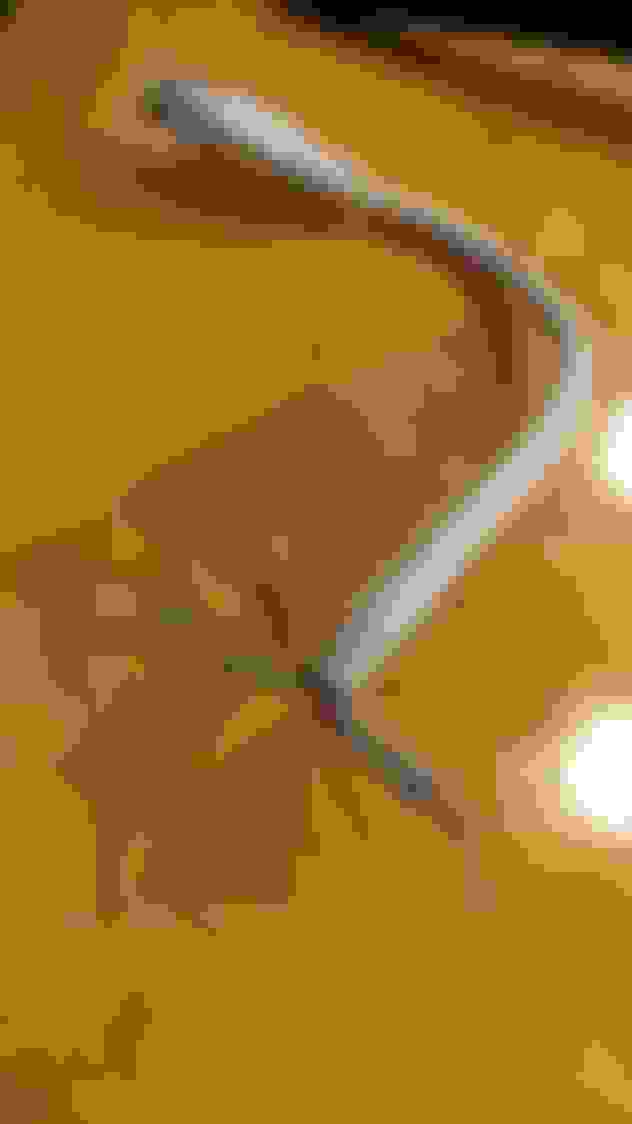
Yes I have a couple pics. The quality of the job isn't that great as I was just trying to see if I can get it working again. As soon as my other capacitors show up, I'm gonna redo everything you see so it's cleaner. All the old brown flux is hard to remove. Is there anything better than alcohol to use? Plus the heat from the iron peels back the wire covering making the leads look too long.
The leads on the flex board side are a little long right now but I'll fit everything better if I get the odo working 1st.
So trying mine again to get it fully operating. I fixed my odometer and replaced all the capacitors so they are good as I also just metered them with a capacitor reader and they are still all good. Checked all the ribbons and copper paths with a continuity and have one problem I am looking at. So at the speedo when you remove it there are two screws and then the 4 solder points to do. What I noticed was there are also 4 other very small pins coming out that don't seem to touch anything but do go in some areas on the board. Basically a diamond shape in the middle of the 4 solder points.
Do these 4 spots need to be touched to the board or are they no related to anything? Seems to be small wire that comes out the back of the speedo assembly. Sorry don't have a picture being at work now but is very easy to see between the two screws to remove the speedo.
Looking at the pictures on the first post, they can be seen and are actually 8 small pins that come through the board along with the 4 large ones.
Last edited by Houstonderk; Aug 9, 2017 at 02:25 PM.
So trying mine again to get it fully operating. I fixed my odometer and replaced all the capacitors so they are good as I also just metered them with a capacitor reader and they are still all good. Checked all the ribbons and copper paths with a continuity and have one problem I am looking at. So at the speedo when you remove it there are two screws and then the 4 solder points to do. What I noticed was there are also 4 other very small pins coming out that don't seem to touch anything but do go in some areas on the board. Basically a diamond shape in the middle of the 4 solder points.
Do these 4 spots need to be touched to the board or are they no related to anything? Seems to be small wire that comes out the back of the speedo assembly. Sorry don't have a picture being at work now but is very easy to see between the two screws to remove the speedo.
Looking at the pictures on the first post, they can be seen and are actually 8 small pins that come through the board along with the 4 large ones.
Houston,
Take a look at this FD Speedometer-Odometer post #3. Look at the middle picture. Those are the only solder connections that link the speedometer to the speedometer circuit board.
It is hard to see what you are talking about without a photo for a reference.