When you click on links to various merchants on this site and make a purchase, this can result in this site earning a commission. Affiliate programs and affiliations include, but are not limited to, the eBay Partner Network.
Connectors 1-4 are standard, connector 5 actually exits the side of the stock ECU. This creates a bit of an issue since it is hard to determine the actual function and how they change the ignition signals, if at all. There is also an additional fuel pump drive signal located on #5.
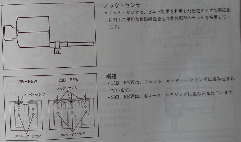
The pinout is similar to the FD, until #2 where it starts to deviate and add in items such as "2H hydro boost signal". 3M knock signal for 20B only does not make any sense, since the front rotor housing is where the sensor is located on the 13B-re and -rew.
The real issue is not having a test vehicle to develop an adapter on. Our Auto FD adapter had countless hours of R&D, even with a test vehicle to use.
The pinout is useful, but we still do know how removal a specific control wire will effect the car or stock ECU.
I totally agree on the test vehicle aspect. Although out of my own curiosity I've been digging into the issues you've identified in the pinout regarding 13B-RE Cosmo vs FD.
First, can you confirm if the ECU in your picture is 20B or 13B-RE? Based on diagrams in the (Japanese language only) service highlights document, the 5th connector looks like it is 20B only for actual function. Of course it is possible that the 20B and 13B-RE have the some ECU hardware with just a different ROM chip in them according to 2 rotor or 3 rotor specification, in order to have common manufacturing of the respective ECUs.
For the 5th ECU connector, here's what I've been able to figure out:
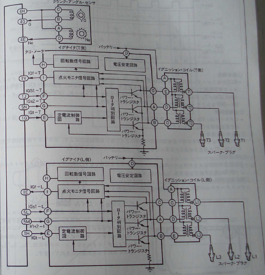
pins 5L and 5M are related to the ignitor on a 20B due to the additional rotor. 20B-RE (ignitor shown on the right, connected to spark plugs)
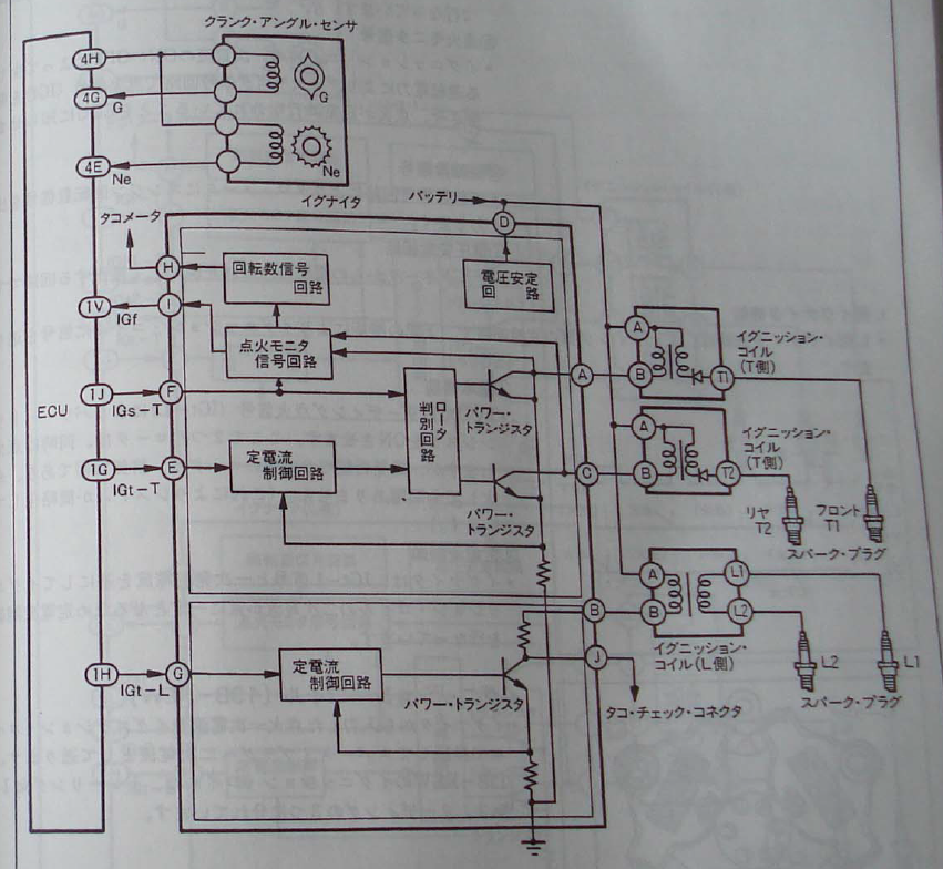
13B-RE (ignitor shown on the right, connected to spark plugs)
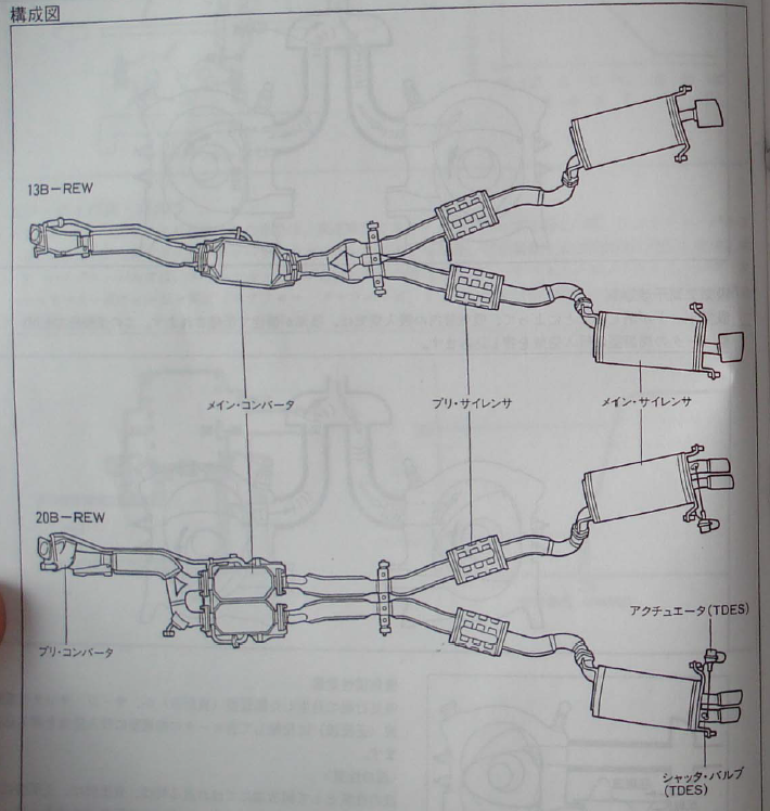
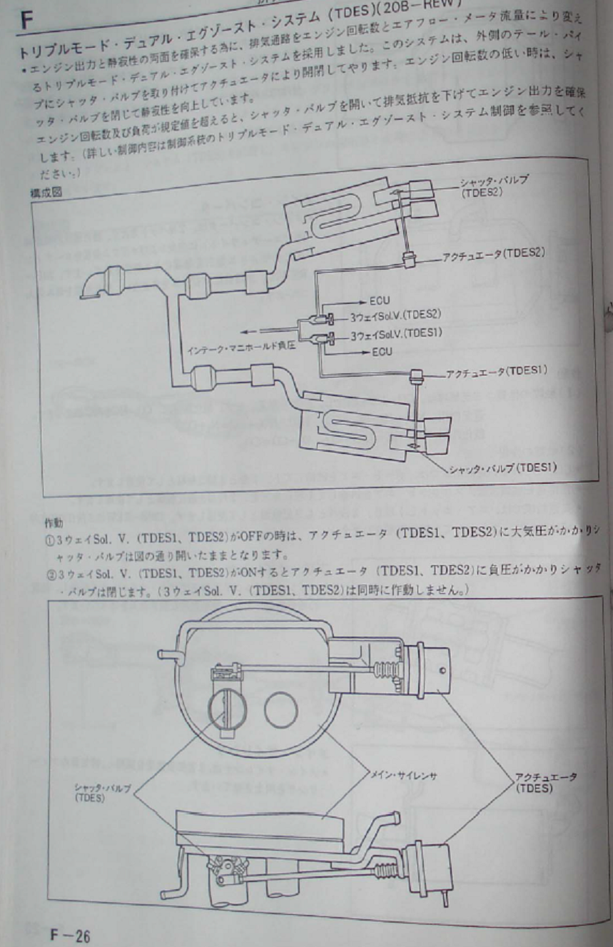
Pin 5E is there because the 20B Cosmo has 2 different variable exhaust butterflies and solenoids while the 13B-RE has only one. This is due to a different exhaust arrangement with an upstream Y pipe and 2 cats on the 20B instead of 1.
For the knock sensor, there is a diagram showing 3 knock sensors on the 20B, and 2 knock sensors on the 13B-RE.
So I'm guessing pin 3M corresponds to the front rotor on a 20B, 3N is the front rotor on the 13B-RE or middle rotor on a 20B, and 3O is the rear rotor on the 13B-RE or 20B-REW. So if you are going to use a plug and play ECU on a 13B-RE with single knock input (such as a Power FC), you'd have to pick which input you want to use, 3N or 3O.
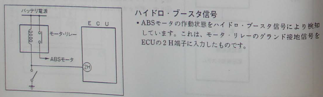
pin 2H looks like it's either a vacuum booster motor or a brake booster related motor, because on the diagnostic condition it mentions brake pedal position. If I get a chance I will dig through the wiring diagrams I have on paper to learn more.
Looks like the "Hydro boost signal" on pin 2H is just an ON-OFF signal from the ABS relay.
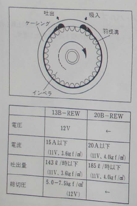
Also, on connector 5 it looks like there is an additional fuel pump resistor relay, maybe a 3 step system on a 20B. The service highlights shows a higher amperage on the 20B fuel pump so it makes sense.
Last edited by arghx; Sep 14, 2017 at 11:35 AM.
Reason: fuel pump
Having the entire manual certainly makes things easier.
The knock sensor picture actually confirms what I said, the bottom arrows are pointing to the leading plugs, top arrow is pointing to the knock sensor(s), 13b-re(w) has one on the front housing, 20B has three, so it would be 3M only, same as the FD.
Edit: to answer your other question, this is a 20B ECU according to the colors for connector 1 having a 3E
Last edited by Banzai-Racing; Sep 14, 2017 at 11:45 AM.
Ok, I took pictures with my phone, cropped them and put them in a PDF. It's not pretty but it should be high enough quality for the basic wiring diagrams of the 13B-RE and 20B-REW ECU.
If I'm trying to figure out what I diagram says, I use the Google Translate app on my phone. It uses the camera and pops up a translation. If you get the right angle it will give a decent enough one to figure out what you're looking at usually (human translation is much better though).
Looks like pin 3M is the knock sensor on the 13B-RE (front rotor only), which is the front rotor knock sensor pin on the 20B.