
Interaction of Charge Relief and Charge Control Valves

Thread Starter
Recovering Miataholic
Joined: Mar 2002
Posts: 1,562
Likes: 53
From: Fountain Valley, CA

I've been trying to understand the relationship between the Charge Relief Valve ("BOV" for secondary turbo) and the Charge Control Valve (actuator control for isolating secondary turbo output air from primary turbo output). The illustration on page F-84 of my 1994 FWM is attached for reference. Note that the control vacuum hose for the Charge Relief Valve is tied to its solenoid valve "B" port, and that solenoid valve's "A" port connects to the Charge Control Valve's solenoid valve "C" port. My little brain cannot grasp what this means, partly because I cannot tell where else the "C" port goes. It sort of disappears downward... is that a connection to the output air from the secondary turbo, or a vent to atmosphere, or just an obscure connection to somewhere not shown?
And what does this all mean?

Last edited by wstrohm; Jan 12, 2009 at 03:27 PM. Reason: Add illustration


Their function and operation is explained pretty well (with nice diagrams) in the Mazda Service Highlights manual, which can be downloaded here. I spent some time figuring out how these work to ensure that I had my standalone EMS configured to activate them properly. Here's my summary:
Charge Control: simple on/off solenoid, actuator controls a valve in the Y-pipe. When the ECU activates this solenoid at low RPMs, the Charge Control valve prevents pressurized air from the primary turbocharger from entering the secondary turbocharger. Turns OFF at high RPMs when the secondary turbocharger is active. From what I can tell, the stock ECU switches this at the exact same RPM as the Charge Relief valve.
Charge Relief: simple on/off solenoid, actuator looks like a blowoff valve attached to the top of the Y-pipe. When OFF at low RPMs, pressurized air from the secondary turbocharger is vented back to the airbox. This allows the secondary turbo to spool up before the switchover point (using exhaust gases sent to it by the prespool valve). The ECU actuates the solenoid at high RPMs, should be the exact same RPM as the Charge Control Valve switching point.
Very good test procedures outlined here by degeesaman:
https://www.rx7club.com/3rd-generation-specific-1993-2002-16/how-test-your-solenoids-actuators-other-turbo-stuff-802060/
-s-

Joined: Jul 2003
Posts: 4,678
Likes: 97
From: Bay Area, CA
I hate to disagree, but the explanation of the operation of these valves in the Service Highlights manual is absolutely terrible and gives only a vague sense of how they interact in the stock sequential system. In fact, every single explanation I have ever seen on the operation of the sequential control system on the FD is terrible.
That said, the CRV is designed to vent boost from the secondary turbo when it is prespooling. It basically vents prespool boost from the secondary turbo to the atmosphere. It closes (ON per the FSM) at the transition point (which is load and rpm dependent).
At the exact same point, the CCV opens (OFF per the FSM) allowing boost from the secondary turbo to join with boost from the primary turbo. Previously the CCV was closed, isolating the secondary turbo boost from the primary, while the simultaneously open CRV guaranteed that any secondary boost generated was vented and did not build up.
Also, at the exact same transition point, the two turbo control solenoids activate the turbo control actuator to direct exhaust gas flow to the secondary turbo in parallel with the primary turbo. Previously, flow was directed only at the primary turbo (the prespool actuator being responsible for bleeding some flow from the primary turbo to the secondary to prespool it).
If all the stars are aligned, the addition of the boost from the secondary turbo will be relative seamless because the secondary will have been prespooled.

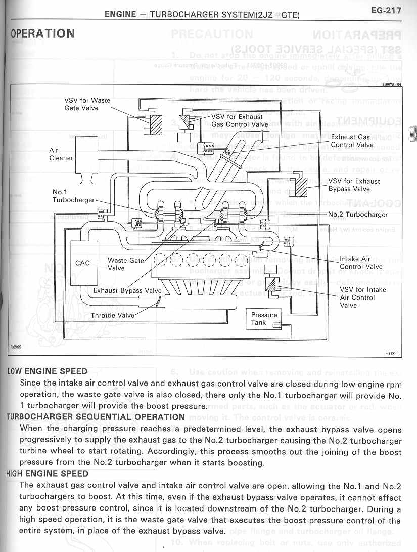
From looking at the vacuum diagram,
The CC solenoid switches between the pressure in the secondary turbo compressor output when off, to stored vacuum when on. The output goes directly to the CC actuator.
The CR solenoid switches between the stored vacuum when off, to the pressure in the secondary turbo compressor output when on. The output goes to the CRV.
Dave
Last edited by dgeesaman; Jan 18, 2009 at 12:25 PM.
Thread Starter
Recovering Miataholic
Joined: Mar 2002
Posts: 1,562
Likes: 53
From: Fountain Valley, CA
Thanks to all for a considerable help here! So the "A" port of the CR solenoid and the "C" port of the CC solenoid are both tied into the secondary turbo output pressure. That was key for me... the drawing is ambiguous (can't see the opening to the secondary turbo "pipe" like I can for the Charge Control Actuator).
Dave,
I think you actually meant "The output goes directly to the CC Actuator," right?
I appreciate all your help, and I downloaded the "Service Highlights" manual to read yet another explanation. I gather that operation of the CC and CR valves is supposed to be simultaneous, and wonder why they were not activated by a single control...? Like a "three-way" solenoid valve that could turn one on while turning the other off...
Dave,
The CC solenoid switches between the pressure in the secondary turbo compressor output when off, to stored vacuum when on. The output goes directly to the CC solenoid.
I appreciate all your help, and I downloaded the "Service Highlights" manual to read yet another explanation. I gather that operation of the CC and CR valves is supposed to be simultaneous, and wonder why they were not activated by a single control...? Like a "three-way" solenoid valve that could turn one on while turning the other off...
I'm not sure why Mazda rigged up everything the way they did. I suspect they got going with the design and just kept on going with the same basic components.
Note that the TC vacuum solenoid looks like a design afterthought and isn't mentioned in much of the literature. I suspect Mazda made some late design changes to the rack.
Note that the TC vacuum solenoid looks like a design afterthought and isn't mentioned in much of the literature. I suspect Mazda made some late design changes to the rack.
Trending Topics
Joined: Jul 2003
Posts: 4,678
Likes: 97
From: Bay Area, CA
My understanding is that the TCA is activated by both a vacuum and pressure simultaneously to ensure that it operates rapidly. Thus two solenoids are needed to activate it. Slow operation of the TCA will give a poor transition because exhaust gasses will not be fed rapidly to the secondary turbo at transition. The TCA will still work if either one (though not both) of its solenoids do not operate but will do so slowly.
Exactly. Per the FSM, the vacuum side solenoid doesn't exist. It also could have been located with the other solenoids, but Mazda didn't. So if it was designed to be a single solenoid but that wasn't enough force, then adding a vacuum side solenoid would have been a good fix.
I'm not saying this is fact, but it's curious.
I'm not saying this is fact, but it's curious.

Thread Starter
Recovering Miataholic
Joined: Mar 2002
Posts: 1,562
Likes: 53
From: Fountain Valley, CA
Where is the vacuum-side TC solenoid located (since it's not on the diagram)?? Took lots of pics when I did my vac hose job, but don't see an unexpected solenoid anywhere... I must be thinking wrong.
Joined: Jul 2003
Posts: 4,678
Likes: 97
From: Bay Area, CA
Exactly. Per the FSM, the vacuum side solenoid doesn't exist. It also could have been located with the other solenoids, but Mazda didn't. So if it was designed to be a single solenoid but that wasn't enough force, then adding a vacuum side solenoid would have been a good fix.
I'm not saying this is fact, but it's curious.
I'm not saying this is fact, but it's curious.
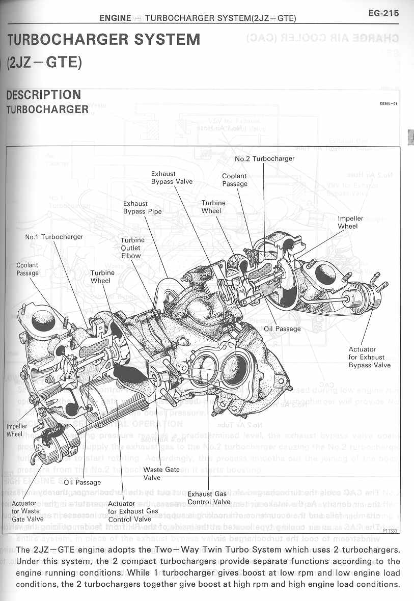
I am really curious about the operation of the Mark IV Supra's twins. I would like to see a list of the solenoids and actuators it uses and whether it is any simpler than what the FD has.
MKIV Supra Turbos:
http://www.mkiv.com/manual/manualtt/...ion/index.html
It appears to be set up similarly, except that the prespool function is handled by a controlled opening of the valve that feeds the second turbo.
http://www.mkiv.com/manual/manualtt/...ion/index.html
It appears to be set up similarly, except that the prespool function is handled by a controlled opening of the valve that feeds the second turbo.
yeah i've been looking at that. There doesn't appear to be a charge relief valve equivalent. Perhaps their charge control equivalent is opened progressively (duty cycle controlled) so that prespool goes right into the main stream of charge air?
On the exhaust side, it looks like the turbo control and precontrol functions are sort of combined in the same valve. Yet there is a valve after the turbine outlet that controls exhaust flow to the main exhaust stream. So as the secondary turbo on the Supra is spooling up, the amount of exhaust going in to the secondary turbo and coming out of it is controlled at the same time.
Doesn't the FD's precontrol valve bleed exhaust that has already hit the primary turbine wheel? So during secondary turbo prespool, the turbo control actuator is closed. The exhaust from both rotors hits the primary turbine wheel first, then after it passes over that wheel the precontrol actuator directs some of it to spin up the secondary turbo.
In contrast, on the Mark IV the rear 3 cylinders directly feed the secondary turbo. This is instead of exhaust gas first passing through one turbo and then hitting the other. This is assuming I understand the FD right and I am interpreting the diagram of the Mark IV correctly. Overall though that does sound mechanically simpler than the FD, although there are probably more duty cycle controlled solenoids (requiring more complex logic in the stock Supra ECU). There doesn't appear to be a vacuum chamber on the Supra either (just a pressure tank), and they don't have any actuators that require both vacuum and boost to operate properly (like the FD's turbo control solenoid).
On the FD you have 2 duty controlled solenoids (precontrol, wastegate) and 4 on/off solenoids (charge control, charge relief, turbo control pressure, turbo control vacuum). I'm speculating that on the Supra, there are 4 solenoids: exhaust bypass--aka turbo control/precontrol, exhaust gas control--no FD equivalent, wastegate, intake air control--aka charge control/charge relief. These may all be duty cycle controlled. It really is a better system. A smarter computer means less vacuum lines and less actuators. I wonder if Toyota engineers knew how the FD system worked when they were designing the system on the Supra.
FD

ok now i'm not sure I am entirely clear on how exhaust gases are directed on the Mark IV, just from these diagrams at least. And it's not like there are many Mark IV's still around with fully working stock sequential twins for me to examine. But clearly the system is simpler than the FD's.
Looking at the mkIV diagrams, I believe these work in basically the same way, with these differences:
1) In the FD, there is a turbo control and precontrol door between the engine and turbos. In the supra the exhaust flow is throttled after the secondary by the exhaust control and exhaust bypass doors.
2) Prespool is done by progressively opening flow through the secondary.
3) Solenoids operate on pressure. While I suspect the supra has vacuum lines for things like evap and other stuff, the turbos don't use it.
4) The more I look at it, I suspect the Supra ECU uses feedback control over these components. If you monitor the pressure on the secondary, you can transition as soon as the secondary reaches the right charge pressure. The FD does not have feedback control, which means the secondary needs to be be prespooled earlier and that requires the charge relief function to allow for blow-off.
5) While I don't see an equivalent to the charge relief, I do see some sort of bypass around the Supra's intake air control valve. If you configured it with a pressure relief valve (set to the boost pressure) you could serve that function. If it fails, it won't affect secondary boost pressure. (On the FD, a leaking CRV will vent off all boost).
With a little bit of feedback control, the FD's system could work more reliably, or at the very least provide valuable information about troubleshooting. 90% of the challenge of fixing the FD system is figuring out where the problem is.
Lining up the components:
(FD) vs. (Supra)
- Turbo Control = Exhaust Control
- Turbo Precontrol = Exhaust Bypass Control
- Wastegate = wastegate
- Charge Control = Intake Air Control
- Charge Relief = none
No. On the FD, exhaust gas reaches the secondary through only two paths - through the precontrol door or the turbo control door. At transition the precontrol goes from open to closed and the turbo control goes from closed to open.
1) In the FD, there is a turbo control and precontrol door between the engine and turbos. In the supra the exhaust flow is throttled after the secondary by the exhaust control and exhaust bypass doors.
2) Prespool is done by progressively opening flow through the secondary.
3) Solenoids operate on pressure. While I suspect the supra has vacuum lines for things like evap and other stuff, the turbos don't use it.
4) The more I look at it, I suspect the Supra ECU uses feedback control over these components. If you monitor the pressure on the secondary, you can transition as soon as the secondary reaches the right charge pressure. The FD does not have feedback control, which means the secondary needs to be be prespooled earlier and that requires the charge relief function to allow for blow-off.
5) While I don't see an equivalent to the charge relief, I do see some sort of bypass around the Supra's intake air control valve. If you configured it with a pressure relief valve (set to the boost pressure) you could serve that function. If it fails, it won't affect secondary boost pressure. (On the FD, a leaking CRV will vent off all boost).
With a little bit of feedback control, the FD's system could work more reliably, or at the very least provide valuable information about troubleshooting. 90% of the challenge of fixing the FD system is figuring out where the problem is.
Lining up the components:
(FD) vs. (Supra)
- Turbo Control = Exhaust Control
- Turbo Precontrol = Exhaust Bypass Control
- Wastegate = wastegate
- Charge Control = Intake Air Control
- Charge Relief = none
Doesn't the FD's precontrol valve bleed exhaust that has already hit the primary turbine wheel? So during secondary turbo prespool, the turbo control actuator is closed. The exhaust from both rotors hits the primary turbine wheel first, then after it passes over that wheel the precontrol actuator directs some of it to spin up the secondary turbo.
Last edited by dgeesaman; Jan 19, 2009 at 11:51 AM.
Joined: Jul 2003
Posts: 4,678
Likes: 97
From: Bay Area, CA
In addition to the lack of feedback control on the FD sequential system is number of failure points. For example, in order for the transition to work properly the PCA, the CCA, the CRV, and the TCA have to do a delicate dance. There are about 20 hoses connecting them, which are also points of failure. The vacuum and pressure chambers and the two associated check valves are also failure points. If any one of these four actuators, five controlling solenoids, ~20 hoses, tanks, or check valves fails a large transition dip may result.
And to make life more interesting, the solenoids can sometimes fail intermittently, working at low temperatures, for example, and failing at higher temperatures.
It is clear that the factory solenoids are not robust units - some even fail testing right out of the box. The check valves also fail regularly as do the vacuum hoses.
So not only is the system complex and very sensitive to failure of individual components but the components themselves are of poor quality. The actuators seem to be the only relatively reliable components in the system.
to me, the exhaust gas control actuator in the Supra looks like it controls the exhaust gases leaving the secondary turbine, not the exhaust gases entering it (like the FD's turbo control actuator). Thus they are not directly analogous.
True, they are on the opposite side of the secondary turbo. But they perform the same function.
No Rotor No Motor =)
Joined: Aug 2009
Posts: 29
Likes: 0
From: Calgary ab canada
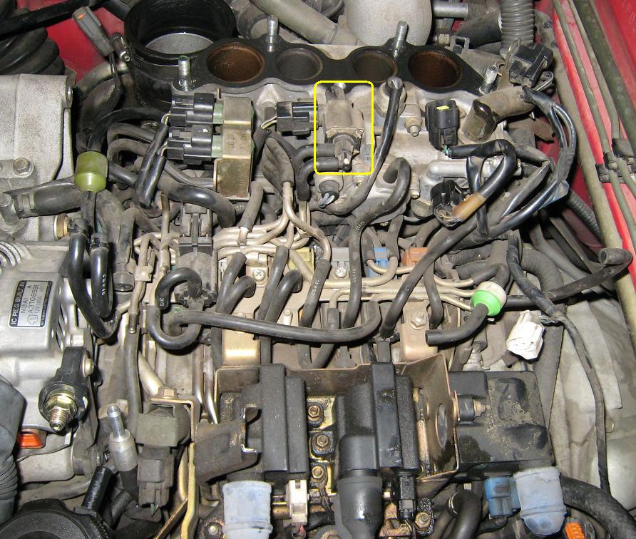
In this picture the main connector coming off of the top of the acv... Where the hell does it connect too? I was re-doing my lines in the rats nest and can't figure out where it goes too.. The connector coming off right beside the top right corner of the yellow box..
Thread Starter
Recovering Miataholic
Joined: Mar 2002
Posts: 1,562
Likes: 53
From: Fountain Valley, CA
In this picture the main connector coming off of the top of the acv... Where the hell does it connect too?
On page Z-31, the illustration pointer to B1-25 points essentially at the valve solenoid itself, so it looks like connector B1-25 must break out of the emission harness close to it.
As far as actually seeing that B1-25 connector, I'm looking for pics of our engine now. Here is a pic of the Air Control Valve out of our car... you can see connectors; the obvious one might be B1-25. And here is another pic of the connection with the rat's nest removed, where you can almost see the connection to the emission harness.

Thread
Thread Starter
Forum
Replies
Last Post
Tem120
3rd Generation Specific (1993-2002)
4
Sep 7, 2015 09:53 AM