When you click on links to various merchants on this site and make a purchase, this can result in this site earning a commission. Affiliate programs and affiliations include, but are not limited to, the eBay Partner Network.
A stock FD RX-7 does not come with keyless entry. A factory keyless entry kit was released in Japan for RHD cars but it is not directly compatible with LHD FDs. Several people have reported adapting this kit to work with LHD FDs but details were always sketchy. So I figured I’d give a step-by-step guide for adapting this RHD keyless entry kit to work with LHD cars.
TL;DR: the RHD keyless entry kit can be adapted to work with LHD cars but requires: (1) substituting an RHD passenger-side actuator-driven lock for the driver-side lock in the kit, (2) doing some electrical harness rewiring (easy), and (3) modifying the substitute RHD passenger lock actuator to work with the kit (not so easy).
RHD Keyless Entry Kit
The RHD keyless entry kit provides a driver-side actuator-based door lock assembly plus some electrical components and harnesses to drive the actuator. Oddly, all stock FDs (either LHD or RHD) come with a passenger-side actuator-based lock already (which is driven by the manual locking and unlocking of the driver door). The keyless entry kit works in tandem with the existing passenger actuator to effectively provide keyless locking and unlocking for both doors simultaneously.
As far as I know, the FD RHD keyless entry kit was released only in Japan. Certainly, the kit I received only had instructions in Japanese. However, it is widely available outside Japan and can frequently be found on eBay or can be ordered directly from Japan. Its part number is F138-V7-600A and it generally sells for a fairly steep $500 or so.
The kit comes with the following main components: (1) an RHD driver-side actuator-based door lock, (2) a remote receiver, which is installed in the driver-side door, (3) an adapter harness for this receiver that wires it up to the stock factory wiring harness in the door, (4) a replacement timer unit that replaces the stock timer unit, (5) an adapter harness to attach this timer unit to the stock factory wiring, and (6) a remote key fob. Step-by-step instructions and a detailed wiring diagram are also provided (in Japanese).
Here are the electronic components that come with the kit.
The timer unit with its adapter harness attached is at the right of the picture. The remote receiver is in the center of the picture, also with its attached adapter harness. To its left is an antenna cable, which plugs into the remote receiver. The remote key fob is at the top middle of the picture and to its left are various Zip Ties and bits and pieces for installing the components
This kit is essentially plug-and-play for RHD cars. Basically, the stock manual driver-side door lock is first replaced with the kit’s actuator-based lock; then the kit’s remote receiver is plugged directly into the factory driver-side door harness using the supplied adapter harnesses; finally, the stock timer unit in the driver footwell is replaced with the kit’s timer unit.
For a variety of reasons the kit will not work directly on LHD cars.
Before describing these reasons, I will give quick overview of stock LHD door lock circuit and then describe the RHD keyless entry circuit.
Stock LHD Door Lock Wiring
The stock door lock circuit on an LHD FD is pretty simple.
Here is the factory wiring diagram.
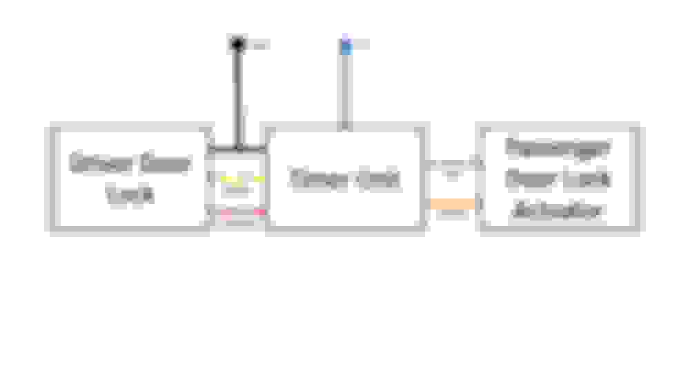
Here is a high-level representation of this circuit. Note that this diagram is a simplified representation of the circuit and that wire colours can change at connector boundaries in the actual circuit.
Basically, the lock in driver-side door has three wires that are used to indicate if the door is locked or unlocked: If locked, the green/yellow wire is connected to the black ground wire; if unlocked, the green/red wire is connected to the black ground wire.
These three wires are routed via the driver-side door harness to a door lock timer unit in the driver footwell. This timer unit is continuously monitoring the state of the driver-side lock.
When the timer unit detects that the driver-side door is unlocked, it sends a 12-volt pulse on the orange wire to the passenger-side door lock actuator, which unlocks the door; when the driver-side door is locked, the timer unit sends a 12-volt pulse on the green wire to the passenger-side door actuator, unlocking the door. The timer unit effectively makes the passenger-side door lock act as a slave of the driver-side door lock.
This timer unit is provided with a constant-on 12-volts via a blue wire.
RHD Keyless Entry Circuit
The keyless entry kit effectively extends this circuitry by adding a remote receiver and a new driver-side actuator-based lock.
Here is the wiring diagram (in Japanese) for the RHD keyless entry circuit.
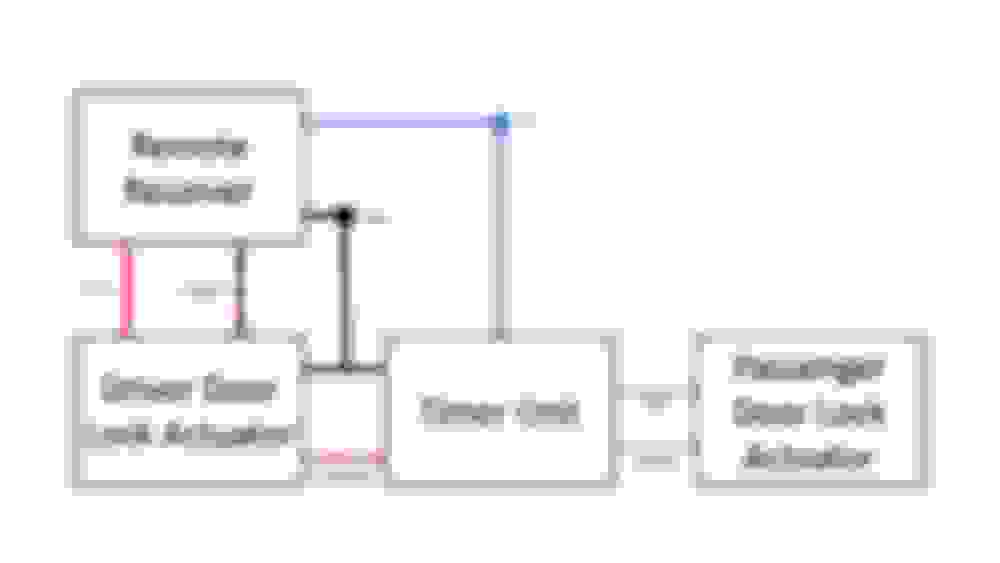
Here is a high-level representation of this circuit. Again, note that this diagram is a simplified representation of the circuit and that wire colours can change at connector boundaries in the actual circuit.
The RHD keyless entry kit adds a new remote receiver that controls a new actuator-driven driver-side door lock. When the receiver gets a lock signal from the remote key fob, it sends a 12-volt pulse on the red wire to the driver actuator, which causes it to lock the door; when the receiver gets an unlock signal, it sends a 12-volt pulse to the actuator on the red/black wire, causing it to unlock the door. The remote receiver also requires a constant-on 12-volt source that it shares with the timer unit.
Again, the passenger-side lock is driven by a timer unit and effectively acts as a slave to the driver-side lock. As with the stock manual lock, the new driver-side lock has outputs for this timer unit indicating whether it is locked or unlocked. While the principle is the same as manual lock, the wiring is slightly different. Instead of having three separate output wires indicating whether the driver-side lock is locked or unlocked, it has two output wires. Essentially, a binary signal is transmitted on green/red wire: this wire is grounded to when the lock is unlocked, and ungrounded when it is locked.
A new timer unit is supplied with the RHD keyless kit to deal with this two-wire signal. When the state of this binary signal on the green/red wire changes, a 12-volt pulse is passed to the passenger-side actuator to lock or unlock it appropriately.
(Why the new lock does not supply the same three-wire signal as the stock system obviating the need for the new timer unit is not clear to me.)
Incompatibilities between RHD Keyless Entry Kit and LHD Cars
As mentioned above, the keyless entry kit will not work directly with LHD cars. There are two sources of incompatibility: (1) The supplied RHD driver-side actuator-based lock will not fit in an LHD driver-side door; mechanically, these lock assemblies are mirror images of each other and cannot be switched side to side, and (2) The adapter harness for the remote receiver is not directly compatible with the factory wiring in LHD driver-side doors.
So, two things are needed to make the kit work in an LHD car: (1) A stock RHD passenger-side actuator-based lock must be purchased for the LHD driver-side door. (Recall, that all FDs—be they LHD or RHD—come with actuator-based locks on the passenger side. An RHD passenger-side lock will physically fit in an LHD driver-side door since they are essentially the same door.) Unfortunately, while this RHD passenger-side lock will mechanically fit in an LHD driver-side door, the actuator attached to the lock does not provide a needed electrical circuit to enable the kit to fully work – so modifications to the actuator are required. (2) The remote receiver adapter harness included in the keyless entry kit must be modified to work with an LHD driver-side door harness.
Required Keyless Entry Kit Door Lock Actuator Modifications
As mentioned, an RHD passenger-side door lock will fit in an LHD driver-side door. This lock is not listed in the US Mazda parts catalogue so must be ordered from Japan. Its part number is F110-59-310C and it costs approximately $350.
However, while it physically fits in an LHD driver-side door, it does not provide all the wiring needed to work with the keyless entry kit. Specifically, it does not include the wires that indicate whether the lock is locked or unlocked. If you recall, the stock circuit has three wires that are monitored by a timer unit that sends a signal to the passenger-side door to lock or unlock it in concert with the driver-side door.
The RHD driver-side door lock that comes with the keyless entry kit includes this circuit.
Here is a picture of the kit’s RHD driver-side door lock assembly with the actuator cap removed.
As can be seen, this actuator has four wires. The green and red wires are used to drive the actuator motor (red is positive to unlock, green is positive to lock). The black and green/white wires indicate the position of the actuator’s locking arm, i.e., whether it is locked or unlocked. All four wires are routed to a 4-way connector.
Initially, I was expecting three signal wires: a common ground wire and two wires that each indicate whether the lock is locked or unlocked. However, if you recall from the keyless entry wiring diagram, the replacements timer unit needs only two wires to detect the state of the lock: a ground wire and a wire that is grounded if the lock is unlocked, and ungrounded if it is locked.
If you look at the picture above, you can see how the mechanism operates. The actuator cap has three curved contacts that are attached to three wire terminals via lines that are embedded in the cap. A two-pronged fork sitting on an arm in the actuator slides over these contacts. One prong of the fork makes continuous contact with the single longer contact whereas the other prong contacts one of the two other contacts depending on the position of the actuator arm. The actuator arm position can thus be detected by monitoring the signal on the wires attached to the actuator cap.
Here, for example, the actuator is in the unlocked position and the arm is angled to the right. If the actuator cap were put in place the bottom prong on the fork on the actuator arm would make contact with the longer curved contact and the top prong would make contact with the lower right contact – thus electrically connecting both contacts. When the actuator is locked, the arm moves to the left and the fork makes contact with the longer curved contact and the lower-left contact.
This circuit state can be monitored by the black and green/white wires that are soldered to the actuator cap terminals. The black wire is soldered to the terminal that is attached to the longer curved connector and the green/white wire is soldered to the terminal attached to the lower curved contact. Thus, when the actuator is in the locked position there is continuity between the green/white wire and the black wire; when unlocked, there is no continuity.
However, the RHD passenger-side/LHD driver-side actuator that we substituted does not include wires to monitor the state of the lock. It has two power wires only. Which makes sense: when used as intended in its RHD passenger-side position the lock does not need to indicate whether it is locked or unlocked since it acts only as a slave of the driver-side lock.
However, we need these monitoring wires. Without them, the keyless entry system will only work for the driver-side door. Not only will the passenger-side door not match the locking state of the driver-side door, but there will be no way to control its actuator – it will become a fully manual door.
In an ideal world, the substitute RHD passenger-side/LHD driver-side actuator would internally have the same fork and contact mechanism with associated terminals as the actuator in keyless entry kit. Then all we would need to do is solder some wires to the appropriate terminals and route them to the two unused positions on the 4-way connector. (Note that we can’t just swap the caps since they are mechanically mirror images of each other.)
However, when we take off the cap of the substitute RHD passenger-side/LHD driver-side actuator we find that it does not have all the necessary internal components.
Internally, the arm is there but there is no fork attached to it to monitor its position. Fortunately, the fork can be easily swapped over from the kit’s actuator.
However, life gets more difficult when we look at the actuator caps. Here are the actuator caps from both types of actuator, with the kit’s cap on the left and the substitute RHD passenger-side/LHD driver-side actuator cap on the right.
While there are positioning marks in the substitute cap, there are no contacts and no associated terminals.
Swapping over the contacts to this cap from the kit’s actuator cap is not trivial. Not only are there no indentations in the substitute actuator’s cap for the three contacts, but the wiring connecting the contacts with the terminals on the kit’s cap is embedded in the cap plastic.
Swapping over the three contacts thus requires making matching indentations in the substitute actuator cap – which is what I decided to do.
The next step is then attaching wires to these contacts. Using the existing matching terminal locations would require running wires inside the cap to the terminal position, which looked prohibitively difficult. Instead, I decided to drill access holes behind the contacts on the substitute cap and solder wires to the back of these contacts, which then exit through these holes.
Here is a picture of the wires soldered to the terminals.
As discussed, only two wires are required: a common ground wire (black) and a signal wire (green/white) that is grounded when the actuator is in the unlocked position, and ungrounded when it is in the lock position.
Fortunately, the black and green/white wires from the RHD keyless entry kit’s actuator can be used here. These wires are terminated with pins that fit nicely into the two unoccupied positions of the substitute lock’s 4-way connector (which is the same as the 4-way connector on the kit’s actuator).
Here are these two wires before their attachment to the substitute actuator cap.
As can be seen, in addition to drilling three holes in the cap to provide access to the rear of the contacts (though note that only two of these holes are needed), I also drilled three holes in the terminal locations to allow the installation of two Zip Ties to provide strain relief for the black and green/white wires.
Here is a picture of the actuator with the wires installed.
I redid the actuator wiring to route all four wires together into the 4-way connector.
This essentially replicates the kit actuator’s wiring.
Last edited by moconnor; Oct 15, 2021 at 07:46 PM.
Finally, I used JB Weld PlasticWeld in the area where the two wires enter the actuator cap to provide additional strength.
Before installing the lock, one final step is needed: the two metal cables going from the lock assembly to the inside door lock latch must be replaced with cables from the kit’s lock assembly. The inside door lock latch is closer to the front of the car on the driver side in FDs so longer cables are required to reach the lock as the back of the door than those on the substitute actuator’s cables, which were intended for use on the passenger side.
Once done, the modified lock assembly can be bolted up.
Required Keyless Entry Kit Door Lock Wiring Modifications
There are two sources of incompatibility between the keyless entry adapter harness and the driver-side door harness in LHD cars: (1) one of the plugs on the adapter harness is physically incompatible with the intended matching plug on the door harness, and (2) the adapter harness has a connector that is designed to connect to a constant-on 12-volt power source but no power source exists in LHD driver-side doors.
Fortunately, these issues are relatively easily addressed.
We will start with the connector incompatibility issue.
Here is the connector on the remote receiver harness that should plug into the driver door harness.
This connector should plug into the center 6-way connector on the driver-side door harness pictured here.
As can be seen, the connector on the remote receiver adapter harness and the door harness connector are not compatible.
Fortunately, instead of sourcing a new connector for the adapter harness, the stock connector that connects to the door harness connector from the original drive-side manual door lock can be de-pinned and reused. This connector is a standard �” Molex unit so it takes widely available �” spade connectors.
The incompatible connector on the remote receiver adapter harness can be removed and the harness wires stripped and terminated with spade �” connectors which can then be inserted into the replacement connector.
The second source of incompatibility takes a little more work. The remote receiver unit requires a constant-on 12-volt source to power it inside the driver-side door. Its adapter harness has a blue wire terminated with a 1-way connector to provide this power.
Here is a picture of this connector.
The instructions indicate that this connector should be plugged into an existing 1-way connector on the door harness. However, no such connector exists on LHD driver-side door harnesses. In fact, no constant-on 12-volt power source is listed in the factory wiring diagram for the driver-side door harness in LHD cars.
I’m guessing RHD cars already come pre-wired with this power source in anticipation of the installation of keyless entry kits, though I could not find a wiring diagram for RHD cars to confirm this.
So, a power wire must be routed to the driver door in LHD cars to power the remote receiver unit.
The wiring diagram for the keyless entry kit (see earlier) indicates that the remote receiver unit uses the same constant-on 12-volt source as the timer unit in the driver footwell. Conveniently, the connector feeding the timer unit sits next to the cabin wiring loom that attaches to the driver-side door harness. So we can tap this power wire and route the wire through to the door harness.
Again, the timer unit connector is a common �” Molex unit so de-pinning the power wire and crimping a �” spade to splice it with a second power wire is relatively easy.
Here is a picture of this connector with this additional power wire installed.
The stock power wire feeding the timer unit through this connector is blue. We used a purple wire to carry the constant-on 12-volt source to the door. This colour was chosen so that it does not clash with existing wire colours in the factory LHD driver-side door harness.
We now need to route this purple wire through to the door.
A Molex connector connecting the cabin wiring to the door harness wiring can be used to route this power wire. It is mounted inside the door jamb.
Here is the female Molex connector in its installed position after the male connector has been removed.
Here it is when removed from the body.
Here is the corresponding male side of the connector.
Fortunately, there are free positions on this connector so we can route our power wire through it. The required male pins and female sockets are from the Tyco/AMP Multilock 070 series, with part number MLC070-PIN for the male pin and MLC070-SKT for the female socket.
Here is a picture of both sides of the connector with the power wire attached to each side.
Here is a picture of the male connector with the purple power wire routed into the door along with the other wires in the driver-side door harness.
Last edited by moconnor; Oct 15, 2021 at 03:16 PM.
We now need to terminate this power wire with a connector so that it can be plugged into the remote receiver harness.
One option would be to terminate the power wire with a matching 1-way connector so that it can be plugged directly in the 1-way connector on the remote receiver harness. However, there is an unused position on the 6-way connector on the door harness, which provides a slightly cleaner option. Since this connector is a standard �� Molex connector we can use a �� spade to terminate the wire and plug it into it.
Here is this connector with the purple power wire installed.
Here is the replacement 6-way connector on the remote receiver adapter harness that mates with it. Here, the blue wire on the adapter harness mates with the purple wire on the door harness; the blue wire thus receives a constant-on 12-volts to power the remote receiver.
For reference, here is the remote receiver harness after we de-pinned its power and door harness connectors.
We terminated these de-pinned wires with �� spade connectors and inserted them into the 6-way Molex connector that attaches to the connector on the door harness.
Once modified, this harness is now ready to be installed.
I will say that functionally this is the cleanest way to do it and it's an interesting project. Would you recommend this over an aftermarket keyless kit? A friend of mine did an aftermarket system way back in the early 2000s. It just had a toggle function, similar to my mom's old Corolla (it didn't know or care whether the door was locked or unlocked, it just switched). From a price and availability perspective, you gotta hunt down specialized parts. This cost what, $700 or more in ordering from Japan?
by the way, are these pics uploaded to rx7club or are they linked to an outside site? They could be dead photos in a few years. Remember when photobucket started holding pics for ransom?
I will say that functionally this is the cleanest way to do it and it's an interesting project. Would you recommend this over an aftermarket keyless kit? A friend of mine did an aftermarket system way back in the early 2000s. It just had a toggle function, similar to my mom's old Corolla (it didn't know or care whether the door was locked or unlocked, it just switched). From a price and availability perspective, you gotta hunt down specialized parts. This cost what, $700 or more in ordering from Japan?
I found the kit for half its retail price in the classifieds and was hoping to find a cheap used RHD passenger actuator but they are hard to find - so ended up buying new. If both the kit and actuator were bought new the total price would be a rather spicy $850. That's a lot more than the price of a typical aftermarket keyless kit and probably hard to justify in general.
by the way, are these pics uploaded to rx7club or are they linked to an outside site? They could be dead photos in a few years. Remember when photobucket started holding pics for ransom?
I have done this a LONG time ago on my FD but a somewhat modified version. This is NOT EASY in the SLIGHTEST.
I did mine probably 15 years ago so a lot of the details are fuzzy. Here's the thousand-foot view:
- I got an entire used LH door actuator from a Japanese car, so Japanese passenger side. This has the actuator motor in it.
- I got a Boa keyless entry kit, this is an aftermarket kit that's JUST a keyless entry with no alarm or anything. It was nice in that it has built-in relays so you don't have any bulky external relays. Nice small box and simple clean fob with another input for a trunk/hatch pop button.
- I got a cut off door harness from a Mazda in the junkyard to use for pins and parts.
Basically I put the US and JDM LH latch assemblies together and made one unit. This was one of the hardest parts. I didn't do any hacking on the actuator motor itself, I left that as-is. The tricky part was moving over the microswitch that registers an unlock/lock event if I remember right. I had to do some drilling and make a small bracket to get that to work. I also remember testing it at one point and one of the screws I used was too long, causing the door to be permanently locked closed, which was....interesting...to fix.
The Boa sent a proper signal to unlock/lock the motor. I then had to do something to make the alarm see it as an "authorized unlock" so it wouldn't set the alarm off. And, of course, the passenger side lock just follows along.
I have seen ways you can achieve similar results with an aftermarket door unlock solenoid that worked well. You can't pull on the cable for the interior door handle, that will eventually fail and you'll have problems. You have to pull on the rods in the door.
Regardless, thank you VERY much for taking the time to write this up. This is NOT an easy project in any way, shape, or form. Anyone looking to tackle this needs to understand 12v wiring, how to read wiring diagrams, and how to engineer around small issues. Budget a full day to do this right. You can do a half-*** job much more quickly but you will have nothing but problems with it.
BTW, I recently bought one of the Viper Boa units on Ebay new in the box for $20. Some of those type of devices are getting harder to find since modern cars all have full power locks and this isn't something people are in the market for. Also a lot of this type of thing have died off somehow with car stereos and car alarms not as popular as they were in the 90's/early 00's.
Awesome wright up! I never got a chance to finish the one I started back in 2019 or the "sketchy" write up, lol. Here's how to program your key fob directly from the OEM keyless entry manual.
Also, the technique above makes a way cleaner install. For my install, I cut the housing for both, and JB weld them together.
Last edited by CREEPENJEEPEN; Oct 15, 2021 at 07:50 PM.
Also, the technique above makes a way cleaner install. For my install, I cut the housing for both, and JB weld them together.
I like this approach too and your post describing it is what inspired my approach. I initially considered trying it but did not feel that I had the tools or the skills!
FYI, I think you will need to swap the green/white wire to the left terminal to pick up the actuator unlock signal.
Basically I put the US and JDM LH latch assemblies together and made one unit. This was one of the hardest parts. I didn't do any hacking on the actuator motor itself, I left that as-is. The tricky part was moving over the microswitch that registers an unlock/lock event if I remember right. I had to do some drilling and make a small bracket to get that to work.
I briefly considered this approach but did not feel that I had a good understanding of how the microswitch worked. And my fabrication skills are marginal.
The advantage of your approach is that it will produce a three-wire lock/unlock signal so that the stock timer unit can still be used, and, more importantly, a cheap aftermarket remote receiver can be used instead of the expensive Mazda one.
I like this approach too and your post describing it is what inspired my approach. I initially considered trying it but did not feel that I had the tools or the skills!
FYI, I think you will need to swap the green/white wire to the left terminal to pick up the actuator unlock signal.
I'm glad you made a better post, it's very well thought out. Yes, correct, I had to switch the green/white wire too. Also, I did it differently for power, I used a vampire tap that was already installed on the harness from the previous owner. It's a green and black wire. I'll post pictures for enthusiast that want options. My way is the faster option but routing a wire through the door like you is the best for longevity.