
How much Vacuum do OMP Nozzles Need to Open?

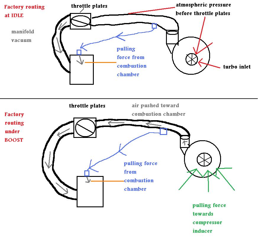
The above pic is incorrect in both ways. For one, the factory has your blue air nipple to the OMP nozzle attached to the pre turbo inlet (constant vacuum source) not after (which is both vacuum and boost). The location in your pic will subject the air line to boost. You should never have boost pressure at the OMP nozzle nipple. The only way the OMP nozzle is subjected to pressure is when the combustion chamber itself is under boost. When the combustion chamber in under pressure (I'm talking pre compression event of the rotor), everything in the intake track (except pre turbo inlet) is under boost pressure.
Edit: I just notice that you were referring to the 2nd gen setup. I don't know the routing of that set-up but your explanation of having a vacuum in a pressurised environment is wrong. You can't have pressure and a vacuum in the same location. Example... The water main to your house is under pressure. Every line it's attached to is under pressure (bathroom, kitchen, exterior line etc). When a turbo is making boost pressure, everything in the turbo outlet becomes pressurized.
arghx the FD in stock form has the oil metering injectors air line connected before the turbo. This is the source they refer to as fresh air. The amount of vacuum created by the turbo at during idle is not enough to offset the vacuum created by the engine. The only significant amount of vacuum created by the turbo would be under boost, but in this case the check valve would be closed.
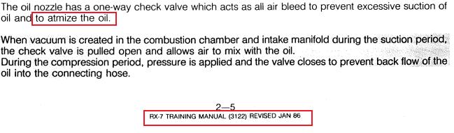
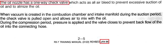
I don't think the air port is for atomization. The nozzles mostly just dribble oil out much like a chainsaw blade receives lubrication. Also I never noticed the compression stroke having an effect on either the oil metering air ports, in which I had a check valve in 1 fail, or on the injector atomizing line. There is no check valve for this line and it will draw a constant vacuum when not plugged or connected to the boost pipes. There is no pulsing of air between intake and compression stroke. But under boost there is definitely pressure from the other side. Both these lines seem to behave similar to any other connection on the UIM or LIM nipples. Positive pressure generated under boost and negative pressure under deceleration and idle.
So the options available are:
Like a Stock FD: Which is right before the turbo inlet
Vented: nothing connected but could allow unfiltered air to enter under vacuum situations
Vented with small filter(s): Allows them to vent without sucking the oil out of the lines keeps air clean
Connected like T2:....? I never knew the T2 was connected to the hard pipe before the throttle body, did these models have a check valve built in? If not this might explain this method. Sounds like this is another option though mazda did away with this design for some reason?


Regarding the T2,
From the factory, the OMP lines are connected to a splitter which connects to a nipple on the UIM. That nipple is a passageway that goes before the throttle plates. It sees boost all the time. In fact, that line blew off on my car and cost me a motor. There is absolutely nothing wrong with the OMP ports seeing boost. Mazda does it from the factory.

On the FD under boost (according to a gauge),
Follow the green arrows from the precontrol and wastegate actuators. The air starts in the compressor outlet (boost), feeds the wastegate and precontrol actuators (there is always air passing through at least one of those actuators), and then goes into a chamber of some sort ( I've never looked at it closely ) that distributes it to the OMP injectors. The final stop is at the compressor inlet. As you can see, the air is being pushed into OMP injectors. There is no major difference among the series 4 through 8 in the atomization design.
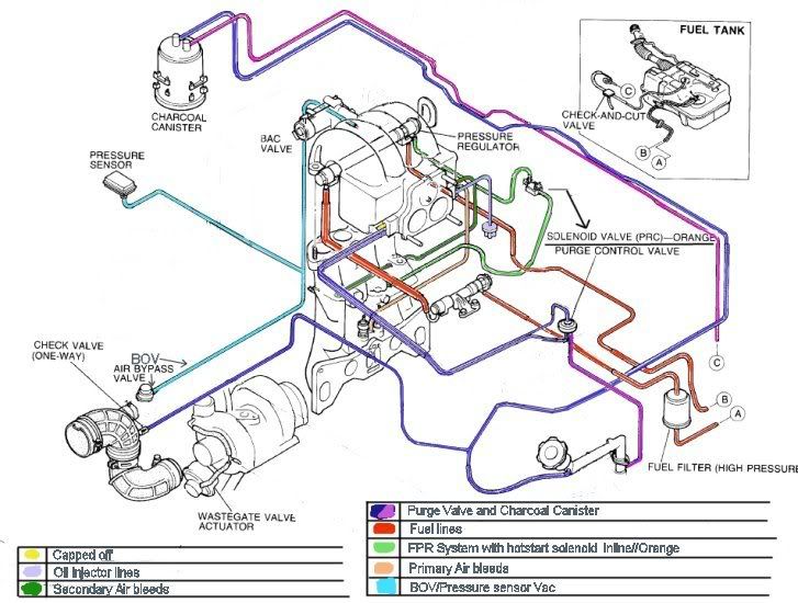
a 2nd gen routing diagram. The OMP has a 4-way splitter for the 4 OMP injectors. The splitter is connected to the UIM. That port never reads vacuum, but I can attest to the boost that comes out of it as it blew off, causing a bad MAP sensor reading and serious detonation.
I disagree.
Also, I am hesistant to use the terms "vacuum" and "boost" because it leads to confusion. I don't want to get caught up in semantics and terminology. If the way I explained some of that seems contradictory, just ignore it or don't otherwise let it obscure my point.
From the factory, the OMP lines are connected to a splitter which connects to a nipple on the UIM. That nipple is a passageway that goes before the throttle plates. It sees boost all the time. In fact, that line blew off on my car and cost me a motor. There is absolutely nothing wrong with the OMP ports seeing boost. Mazda does it from the factory.
On the FD under boost (according to a gauge),
Follow the green arrows from the precontrol and wastegate actuators. The air starts in the compressor outlet (boost), feeds the wastegate and precontrol actuators (there is always air passing through at least one of those actuators), and then goes into a chamber of some sort ( I've never looked at it closely ) that distributes it to the OMP injectors. The final stop is at the compressor inlet. As you can see, the air is being pushed into OMP injectors. There is no major difference among the series 4 through 8 in the atomization design.
a 2nd gen routing diagram. The OMP has a 4-way splitter for the 4 OMP injectors. The splitter is connected to the UIM. That port never reads vacuum, but I can attest to the boost that comes out of it as it blew off, causing a bad MAP sensor reading and serious detonation.
I don't think the air port is for atomization.
Also, I am hesistant to use the terms "vacuum" and "boost" because it leads to confusion. I don't want to get caught up in semantics and terminology. If the way I explained some of that seems contradictory, just ignore it or don't otherwise let it obscure my point.
Last edited by arghx; Jun 17, 2009 at 12:32 AM. Reason: diagrams etc
Okay I wasn't sure if that was a description for the FD or the T2. I wonder why they changed the design on the FD and gave it just filtered air rather then pressurized air like it's predecessor. Maybe they were kinda learning as they went too. Which is why everyone is now so confused. lol
Screw it, just hook them up to something....... anything, including nothing haha.
Just make sure the check valve works or you will have a mess.
Screw it, just hook them up to something....... anything, including nothing haha.
Just make sure the check valve works or you will have a mess.
I wonder why they changed the design on the FD and gave it just filtered air rather then pressurized air like it's predecessor.
The overall design is the same between the 2nd and 3rd generation cars. But like everything on the FD, it's just more... confusing.
Yes even in the diagram you can clearly see the teal colored line connects to the plastic elbow on the primary turbo, this elbow doesn't have pressure the filter connects to this elbow. I don't know what the turbo control solenoids are doing on that line, either they vent back here somehow or the labeling is not clear, but I clearly remember the oil metering lines going to that plastic elbow which definitely does not have positive pressure.


I read this and am confused. I just installed single turbo. I want to keep my omp. Do I route these lines to the turbo filter? Open to air with filter? Or just connect it to one of the unused ports on the UIM? or..other?
From the factory, these OMP 'breather' lines get filtered air from the turbo filter. Running a new line to the turbo filter on your new setup should be fine.
Many people, myself included, have connected them to atmosphere using small breather filters. Doing this should be fine also.
Routing them to the intake manifold will cause problems, don't do that.
Many people, myself included, have connected them to atmosphere using small breather filters. Doing this should be fine also.
Routing them to the intake manifold will cause problems, don't do that.
Mechanical Engineering
Joined: Jun 2004
Posts: 1,618
Likes: 26
From: South Carolina
I know this is resurrecting an old thread, one thing missing from the check valve, vacuum, boost, conversation is that the nozzles see the same oil pressure the engine is generating. So you must consider the differential pressure between the air and the oil pressure. As long as you're not generating more boost than you are oil pressure you should have a positive gauge pressure at the nozzle so oil is going IN the nozzles.
I don't think that's correct. The oil pressure that the rest of the motor sees is regulated by the OMP (literally the metered part).
The job of the vacuum line to the nozzle is to allow the motor to suck air in at low load when there's no oil being metered in by the OMP, otherwise, the motor would suck oil out of the lines, which would then be empty for a moment under load, when it occurs, before the OMP could refill them.
The nozzles have a super low crack pressure, like less than 1 PSI. But vacuum/boost aren't used to activate or trigger oil injection. The nozzle is just a banjo fitting with a check valve on top of it.
Final thought: If a nozzle becomes blocked, or the check valve fails, you'll get oil wherever its routed to, and it can be a mess, but it's nowhere near the mess you'd get if it was a constant 90psi oil.
Last edited by ptrhahn; Feb 10, 2024 at 10:47 AM.
I’m not so sure on the FD, but the Renesis S1 OMP is a positive displacement metering pump driven off the e-shaft that has no engine oil pressure at all
so I’m going to speculate that the engine oil pressure statement is possibly not correct.
.
so I’m going to speculate that the engine oil pressure statement is possibly not correct.
.
Being a non-engineer I probably said it incorrectly, but its what I meant to imply. Any oil in the OMP lines is put in there by the OMP, and not under engine oil pressure. I'm not sure if the OMP sees any pressurized input, but whatever comes out of it is not engine oil pressure.
Mechanical Engineering
Joined: Jun 2004
Posts: 1,618
Likes: 26
From: South Carolina
Semantically speaking, "metered" in this sense is not pressure, it's volume. It is metering a volume of oil to the engine combustion chamber. If it was pressure, then it would be called a regulator. But the combustion chamber doesn't care about the pressure of the oil, it's the volume of oil.
What I meant on the differential pressure is the difference between the pressure inside the chamber and the pressure on the air inlet of the nozzle. If the pressure in the chamber is lower than the nozzle inlet, oil and air will be sucked into the chamber. If the pressure in the chamber is equal to or greater than nozzle inlet, the check valves are closed. In which case, the positive displacement of the OMP will push oil into the chamber.
At low load, the cam in the OMP has no movement, and thus no positive displacement. The spool (sector valve) takes in oil at current engine pressure, and then the spool bleeds the pressure off into the OMP line. So it's more like a dribble at low load. (shown in the 1800ohm position in the graph below). At low loads (no boost), the engine vacuum sucks out the oil and uses the air to atomize the oil.
At high load the cam in the OMP has about 2.5mm of movement, and that changes it to a positive displacement pump. So, like before, the spool takes in engine oil pressure, and then when the spool is aligned with the outlet ports you bleed the oil into the line. But now, you also drive the cam forward and push more oil volume through the line, and forcing oil into the combustion chamber. (shown at the right on the graph). Under boost, the check valves prevent air being forced out of the nozzle air port and into the oil line.
So the oil pressure in the spool is at engine oil pressure, then it closes off and that pressure is stored in the spool. When the spool is aligned with the outlet port the spool pressure gets bled into the line.
And the plastic lines are really small OD/ID so they can take a lot of pressure. Commercially available nylon lines the same size can easily take ~200-300psi. Think of a road bike bicycle tire, You pump those things up to 80-90psi, but a drag tire is like 3psi. It's all about the volume. But I digress, the plastic lines aren't a limiting factor in the OMP's operation.
from the omp declassified thread.
https://www.rx7club.com/3rd-generati...art-ii-895388/


I don't think that disagrees with what I said, save for one point. I don't think the oil in the OMP lines is at engine oil pressure. I've had the check valve in the nozzle let go several times, and while it's a mess, it's not a 100psi of oil mess.
Mechanical Engineering
Joined: Jun 2004
Posts: 1,618
Likes: 26
From: South Carolina
Here are some simplified pictures of the operation.
1. When the spool is rotated and aligns with the engine oil pressure port, (p1) the body of the omp is filled with engine oil pressure (p2=p1).
2. The spool rotates, trapping the engine oil pressure. So p2 is still equal to p1.
3. The spool rotates to the omp line port. At the instant the port is uncovered the body pressure (p2) is still at engine oil pressure. And then the pressure is bled off to the line pressure (p3) because the volume of the line is much greater than that of the body, and the line pressure is at or below ambient because of the check valve direction.
So for a very very short instant, and a very very short distance the omp line pressure at the omp is at engine oil pressure, at the nozzle, it's definitely negligible. Is it going to build up to engine oil pressure if the check valve is blocked? Under low load/rpm? No, there's no pumping action. Under high rpm/load? Maybe? I haven't tested how much pressure the pump is capable of producing.
And even with that said, the OEM lines have way more pressure holding capability than required. They are in no way a weak point of the system. The only reason to upgrade them is because you can't find the OEM ones or just want bling.


Thread
Thread Starter
Forum
Replies
Last Post
Necrodead
2nd Generation Specific (1986-1992)
5
Jul 31, 2022 12:25 AM
JDM_FC
2nd Generation Specific (1986-1992)
11
Jul 16, 2009 09:33 AM
2713ddddavid
2nd Generation Specific (1986-1992)
12
Sep 2, 2008 07:57 PM