
Help debug another boost issue. Seq turbos, PFC boost control


Help debug another boost issue. Seq turbos, PFC boost control
I've spent lots of time doing searches and testing out parts, but still stumped on this. Would appreciate any input/suggestions. I'll run you through my symptoms and what I've done so far.
I have 99spec turbos running in sequential and I'm attempting to do boost control via the pfc. I'm trying to get 13lbs boost on the primary and secondary turbos. Initially I was getting a solid 13psi on the primary, but on the secondary it would bounce between about 10 and 13psi (oscillating between the 2).
I figured the oscillating boost might be due to the wastegate and pre-control "pills" which are built into the compressor housing on 99 spec turbos. I drilled out the pills, but now I see a solid 9-10psi on the primary and secondary turbos no matter what I set the boost values to in the pfc. 9-10psi seems to be the extent of the range I can control via the pfc.
This is what I've tested so far:
-I pulled off my y-pipe and blew air towards the intercooler side. Seems to hold pressure so I don't think there's a boost leak there.
-I pulled out the wastegate and pre-control solenoids and testing them; Port A holds 15psi, a 9v battery triggers the solenoids to open, I see 30ohms across the connector leads. Looks good.
-I tested both the pressure and vacuum tanks. Both check out.
Most recently I pulled the wastegate hose between the turbo compressor housing and the wastegate actuator to see what would happen. This caused the primary turbo to boost about 10-11 and the secondary to hit about 15psi and then fuel cut kicks in. This leads me to think that there definitely isn't a boost leak in the system.
So what gives? :/ Only thing I can think of is maybe the wastegate solenoid isn't able to vent enough pressure to allow boost to build past 10psi even though according to my tests they checked out ok. As I understand it, the more pressure the solenoid vents, the higher your boost pressure. Is there anything else I can look into?
I'm thinking about replacing the 2 solenoids with the mac 3 port solenoids, similar to Sandro's setup, but it didn't seem like he had an issue boosting over 10lbs on his stock solenoids.


besides basic mechanical checks (boost leaks etc) you need to post Datalogit logs and your map.
There is a turbo transition setting as well as primary and secondary [pre and post transition] boost settings. We need to see the logged dutycycle curve.
There is a turbo transition setting as well as primary and secondary [pre and post transition] boost settings. We need to see the logged dutycycle curve.
My suggestion would be to place an oem pill in your wastegate line. You can order the hose with the pill in it from any mazda dealer. Once this is in place, you will likely be back to your original boost pattern. From there, you can enlarge the hole in the pill gradually until you reach your desired boost level. You may need to replace the prespool pill also.
Your original problem may be due to the limits of the oem wastgate, which may need to be ported. What are your mods?
Your original problem may be due to the limits of the oem wastgate, which may need to be ported. What are your mods?
Haven't pulled logs from my datalogit yet, but makes sense, I'll work on this.
Adam,
My thoughts regarding the pills was that they're optimized for the oem parts and boost level so I thought better to remove them from the mix. What exactly are they doing anyway? Seems like they slow and even out changes in pressures to the actuators so that the actuators are less "jumpy". Not sure why removing them would cause me not to be able to hit the boost level I was previously able to. It's possible that removing them is unrelated to the change in boost and instead the removal and reinstall of all the parts triggered something else to change.
I have already ported the wastegate, but I thought that has more to do with boost creep. Car also has a fmic, downpipe, rb catback, M2 intake, efini y-pipe, greddy elbow, 1300 secondaries, supra pump, all emissions is intact. Pretty much the same as your setup except for the IC now that I look at it
A smaller hole in the wastegate line "pill" will act to increase your boost. The trick is how much to enlarge the hole in order to reduce the boost to a level that is acceptable to your needs, and will make adjustment thru the PFC possible.
I suggest you try opening up an eom pill ever so slightly, The pills can be easily removed from the line with a phillips screwdriver. Once removed they are very easy to drill out. I think they may be made of a heat resistant plastic, so drill just a little at a time. Be sure that you can see thru the hole in the pill when you place it back in the line. This is very important.
I suggest you try opening up an eom pill ever so slightly, The pills can be easily removed from the line with a phillips screwdriver. Once removed they are very easy to drill out. I think they may be made of a heat resistant plastic, so drill just a little at a time. Be sure that you can see thru the hole in the pill when you place it back in the line. This is very important.
Well that was interesting... I setup fc-edit to log the data from the different sensors and after some fiddling to get it setup I noticed that PC% and WG% are stuck at "1" and never change.
Although, now that I think about it, I only looked at the data while revving in neutral. Does the PFC know not to mess with the WG and PC values while in neutral? I'll take do another test this evening unless someone can confirm that the readings do seem strange even in neutral.
Although, now that I think about it, I only looked at the data while revving in neutral. Does the PFC know not to mess with the WG and PC values while in neutral? I'll take do another test this evening unless someone can confirm that the readings do seem strange even in neutral.
Did some more logging tonight and came up with some interesting findings. The results seem a little odd to me, but that could very well be because I have little idea of what I'm supposed to see. For one, I have no idea why rpm didn't show up on the graph. The real-time read out showed correct values, but no graph.
What I found odd is that WG% and PC% are pegged to 1 even as rpm climbs at WOT until somewhere in the 2700 to 4000 range (depending which run I'm looking at). Then all of the sudden they jump to the 220+ range. Is that normal?
Boost on the graph gets up to a value of "50" which corresponds to about 9psi on my boost gauge.
PC% drops back to 1 at about 4300 rpm which I think makes sense because it's job is done once the secondary turbos kicks in.
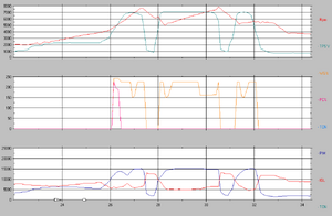
On the first graph I did a run from 2500 rpm to 7500. The sudden jump in WG% and PC% is at 2700 rpm.
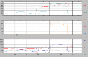
On the second graph I did 2 consecutive runs. First in 2nd gear, then in 3rd gear. I started at 3500rpm, but WG% and PC% didn't move until 4500rpm this time. The 2nd jump in WG% was at 6300 rpm.
I think it's possible there's a short in the car somewhere. Some odd things have been happening. For example, I have a LED dome light and it seems to be outputting a very low amount of light even when the doors are closed. Also my alarm seems to work sometimes but not other times. Could that possibly be leading to odd readings on the solenoids?
Any insight into what's going on here would definitely be appreciated.
What I found odd is that WG% and PC% are pegged to 1 even as rpm climbs at WOT until somewhere in the 2700 to 4000 range (depending which run I'm looking at). Then all of the sudden they jump to the 220+ range. Is that normal?
Boost on the graph gets up to a value of "50" which corresponds to about 9psi on my boost gauge.
PC% drops back to 1 at about 4300 rpm which I think makes sense because it's job is done once the secondary turbos kicks in.
On the first graph I did a run from 2500 rpm to 7500. The sudden jump in WG% and PC% is at 2700 rpm.
On the second graph I did 2 consecutive runs. First in 2nd gear, then in 3rd gear. I started at 3500rpm, but WG% and PC% didn't move until 4500rpm this time. The 2nd jump in WG% was at 6300 rpm.
I think it's possible there's a short in the car somewhere. Some odd things have been happening. For example, I have a LED dome light and it seems to be outputting a very low amount of light even when the doors are closed. Also my alarm seems to work sometimes but not other times. Could that possibly be leading to odd readings on the solenoids?
Any insight into what's going on here would definitely be appreciated.
Trending Topics
arghx,
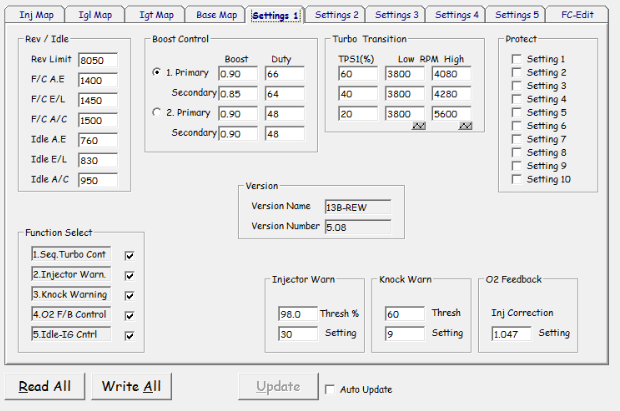
Just reread your post. Here are some additional settings. Let me know if there's anything else that I need to show.
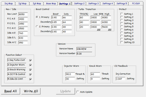
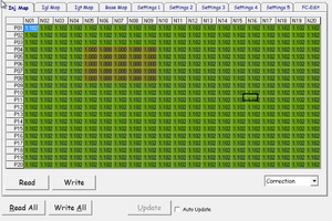
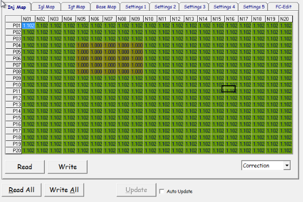
What's with the group of "1.000"s on the ignition map when all the other values are "1.102"?
Just reread your post. Here are some additional settings. Let me know if there's anything else that I need to show.

What's with the group of "1.000"s on the ignition map when all the other values are "1.102"?
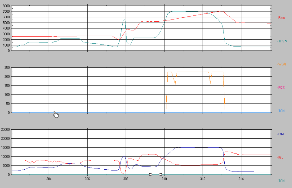
Grabbed some better charts this time around. Still getting about 9psi max.
The WG% control doesn't seem to be very fine grained. Also I can't really draw a correlation between the WG% actions and the PIM reading even though PIM seems to be very stable (albeit not at the value I want).
I tried to graph the TCN sensor (turbo control), but wasn't able to get it to show properly. I'm not sure if I'm setting it's "min" and "max" values incorrectly, but it always seems to show value of 0 when i set the max to either 1 or 250. Not sure if this means it's not working correctly.

read this thread https://www.rx7club.com/3rd-generati...tified-841821/ and note the datalog screenshots shown in post #2 and post #31. If you look through that thread I basically reverse engineered the sequential system in terms of the hardware and how the PFC controls it.
it explains the wastegate and precontrol. When the engine isn't going into boost, there doesn't need to be duty cycle on the precontrol or wastegate. Higher duty cycle keeps the actuator shut, so when duty goes to 0 it means the actuator is being allowed to open.
When you are displaying TCN and CCN, they are bits, so there is only "ON" with a value of 1 and OFF with a value of 0. So set the range in the chart setup for the trace as 0 to 1. Then you'll see it switch high and low. When the value is "1" , the output from the PFC is enabled, which means the ground is switched on. It doesn't necessarily correlate to the state of the actuator. I know that sounds confusing, but notice how TCN and CCN switch in opposite ways at the turbo transition point. That is because a "1" for Charge Control Valve (CCN) corresponds to a ground being switched to the charge control solenoid and vacuum being applied to close the actuator. "0" corresponds to the switched ground being disabled and vacuum being relieved in order to open the actuator. You have to think in terms of the software aspect, the electrical aspect, the pneumatic aspect, and the mechanical aspect.
The PC % is 0-255 and WG % is 0-255 , with 255 being 100% . That's just how the datalogit software displays them. They should have converted to regular % units but I guess the datalogit software guys never set it up to do that.
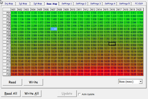
The map you are looking at is the injection correction map. It applies a percentage adjustment to the injection pulsewidth. Those are just correction numbers, whatever was last put in there. Looks like somebody richened up the whole map except that area, probably for fuel economy. I do that kind of thing all the time--it's a shortcut of sorts. You need to look at the "Base x INJ" view in the base tab to see the calculated pulsewidth.
it explains the wastegate and precontrol. When the engine isn't going into boost, there doesn't need to be duty cycle on the precontrol or wastegate. Higher duty cycle keeps the actuator shut, so when duty goes to 0 it means the actuator is being allowed to open.
When you are displaying TCN and CCN, they are bits, so there is only "ON" with a value of 1 and OFF with a value of 0. So set the range in the chart setup for the trace as 0 to 1. Then you'll see it switch high and low. When the value is "1" , the output from the PFC is enabled, which means the ground is switched on. It doesn't necessarily correlate to the state of the actuator. I know that sounds confusing, but notice how TCN and CCN switch in opposite ways at the turbo transition point. That is because a "1" for Charge Control Valve (CCN) corresponds to a ground being switched to the charge control solenoid and vacuum being applied to close the actuator. "0" corresponds to the switched ground being disabled and vacuum being relieved in order to open the actuator. You have to think in terms of the software aspect, the electrical aspect, the pneumatic aspect, and the mechanical aspect.
The PC % is 0-255 and WG % is 0-255 , with 255 being 100% . That's just how the datalogit software displays them. They should have converted to regular % units but I guess the datalogit software guys never set it up to do that.
The map you are looking at is the injection correction map. It applies a percentage adjustment to the injection pulsewidth. Those are just correction numbers, whatever was last put in there. Looks like somebody richened up the whole map except that area, probably for fuel economy. I do that kind of thing all the time--it's a shortcut of sorts. You need to look at the "Base x INJ" view in the base tab to see the calculated pulsewidth.
It's kind of non-obvious but the "boost" setting doesn't have anything to do with controlling boost. As far as I know, the only purpose that setting has is to set the overboost protection. You need to adjust the wg duty cycle setting to actually increase or decrease boost. Obviously you cannot decrease boost lower than your wg spring setting + any creep you might incur in your setup. Increasing the WG solenoid duty cycle will increase boost.
It's kind of non-obvious but the "boost" setting doesn't have anything to do with controlling boost. As far as I know, the only purpose that setting has is to set the overboost protection. You need to adjust the wg duty cycle setting to actually increase or decrease boost.
https://www.rx7club.com/single-turbo...ontrol-900599/
arghx,
That's a great thread with a good explanation as to how the system works. Feel like I've studied most of your posts at this point. I'll see if i can log the TCN and CCN properly later today, but my feeling is that those actuators are working properly. The transition has always worked properly and I get up to 15psi (until fuel cut) when I pull the WG actuator hose.
Seems like something is going wrong with the PC and WG solenoids controls. I'm seeing 15000 on the PIM line which is about 7psi which is the WG actuator spring pressure. That would mean that the WG solenoid isn't dumping any pressure, correct? The strange thing is, on my boost gauge it's reading closer to 8-9psi. Maybe a slight difference in actuator spring tension and boost gauge reading?
Where do Port B on the PC and WG solenoids route to? Is it possible there's a clogged line there? As long as they can vent shouldn't they operate correctly? What happens if I just unhook the port B vacuum lines?
What's the best way to test that the PC and WG solenoids are actually getting the correct signal from the pfc? Is it possible the logs are showing what the pfc intends to duty cycle the solenoids at, but the actual solenoids aren't receiving the signal? I assume a basic connectivity test from the leads on the pfc side of the wiring harness to the solenoid connectors would be a valid test.
I agree that your boost curve is suspiciously maxing right around the rated spring pressure.
log a WOT pull with the solenoids electrically plugged in (like they are now) and then do it again with the solenoids unplugged. Also make sure you don't have the precontrol and wastegate plugs crossed. Do those tests back-to-back just so you have similar ambient conditions. If it's behaving the same with the solenoids unplugged, you've got something wrong. It's possible you have some hose routing messed up somewhere.
I can't recall ever seeing a solenoid driver in the PFC failing or a solenoid itself failing so those should be low priority for troubleshooting. Electrical problems are unlikely unless the harness has been modified and a wire was affected, or you have a bad ground or something. If there is an electrical problem, the root cause is most likely in the harness itself or like a loose ground wire. The solenoid itself are easy checks--apply 12v and ground and see if it clicks.
I'm beginning to wonder if the root cause is an electrical issue. Are there any obvious signs that would indicate a bad ground somewhere? I've noticed that attempting to close the windows when they're already closed will cause the car's idle to drop maybe 100rpm. Not sure if that's normal. Maybe the battery is not in great shape, but I thought the alternator would compensate for that while the car is running.
Also I tried installed some led brake lights, but they seemed to short in the tail light on/brake light off setting if the brake light on + connecter lead was touching the break light + lead on the bulb. Regular bulbs work fine. Pretty odd.
I tested the WG and PC solenoids with a 9v battery and they both click as expected and hold and release pressure properly.
Nothing on the harness has been purposely cut. The car was actually bone stock until not too long ago. All recent mods done under my ownership. An alarm was put in with some potentially suspect wiring. Not sure if that could be impacting the electrical system.
Everything checks out ok on the pfc sensor check menu.
Everything checks out ok on the pfc sensor check menu.
I'm running some connectivity tests from the WG and PC connectors to the connector into the pfc and I'm seeing some interesting results. Am I correct in assuming that the solenoid connector ground pins should link to the sensor ground pin (4d) on the ecu connector? When I test across that the resistance seems to jump all over the place.
Also when I test across the solenoid ground pins and the injector pins on the ecu connector (4w,4x,4y,4z) I see a consistent 14.4 ohms. That doesn't seem right. Does that indicate a short somewhere?
Also when I test across the solenoid ground pins and the injector pins on the ecu connector (4w,4x,4y,4z) I see a consistent 14.4 ohms. That doesn't seem right. Does that indicate a short somewhere?
Ignore that last post. Turns out connectivity testing across the engine harness is more complex than I thought. The sensor ground isn't enabled until the ignition is on. Turning on the ignition and then testing produced the expected/working results. Also, I think testing from ground on the WG and PC connectors to the injector pins on the ecu harness was really just testing the resistance across the injectors. In that case 14.4ohm is probably the expected resistance across each injector.
I ran some test runs with the WG solenoid plugged in and unplugged and did see higher boost with the solenoid plugged in. This would indicate that the wiring is ok and the solenoid is venting some pressure from the actuator.
I read some more about how the stock boost control system works and I've come to the conclusion that I've just made some idiot mistakes in my understanding and configuration. It makes sense that I can't get over 9lbs or so now that I've drilled out the pills. Basically (if I understand correctly now) the WG solenoid is getting completely overloaded with boost pressure now that the pill restriction is gone and isn't able to vent enough pressure to get the pressure within the WG actuator low enough that it will decrease the opening of the wastegate valve. In other words, you have to have some sort of pill/restriction in place when using the stock 2 port solenoids.
Given that, I still have no idea what was causing the boost oscillations I was originally getting with the pills in place. Possibly some odd dynamic between the size of the stock WG pill, the level of boost I was trying to run and the flow rate of my modified intake/exhaust that I was never able to get right.
I've decided to stop mucking about with this rigged up setup and do it properly so I've ordered up a pair of MAC 3 port solenoids to place between the turbo housing and the WG and PC actuators. I'll report back on this setup once I get it installed.
I suggest you try opening up an eom pill ever so slightly, The pills can be easily removed from the line with a phillips screwdriver. Once removed they are very easy to drill out. I think they may be made of a heat resistant plastic, so drill just a little at a time. Be sure that you can see thru the hole in the pill when you place it back in the line. This is very important.
ya I probably should have taken that approach from the start, but I didn't have a proper understanding of how the system worked and w/ my 99spec turbos the pills are built into the turbo compressor manifold which is harder for me to get a drill to so I didn't want to risk having to rip things apart multiple times.


Thread
Thread Starter
Forum
Replies
Last Post