
"free" Power FC single turbo (and probably nonsequential) boost control


"free" Power FC single turbo (and probably nonsequential) boost control
Executive Summary
Based on my recent experiments on a street ported car with a T04R and 13psi wastegate spring: If you want the Power FC to control boost somewhat like the expensive Apex'i boost control kit for single turbo cars (which I've never used and seems to be poorly documented), you need the factory wastegate solenoid still plugged in (use the WASTEGATE harness plug, not the precontrol plug). You also need $10 in hardware store plumbing fittings, some vacuum hose, and a Datalogit.
First, run a line from the side port of the wastegate to a pressure source (I prefer braided line for this port). Now run a pressure source to the bottom nipple of the factory wastegate solenoid. Run a line from the top port of the wastegate solenoid to a 1/8 NPT female tee. Two parts of the tee should be 1/8 NPT male ---> 3/16" barb. Those two will have hoses attached to them. One 3/16" barb has a hose from the solenoid to the tee and one 3/16" barb has a hose from the tee to the top port of the wastegate. The 3rd part of the tee is a 1/8 NPT male --> 1/8" barb to vent pressure from the top chamber of the wastegate so your wastegate doesn't stick shut.
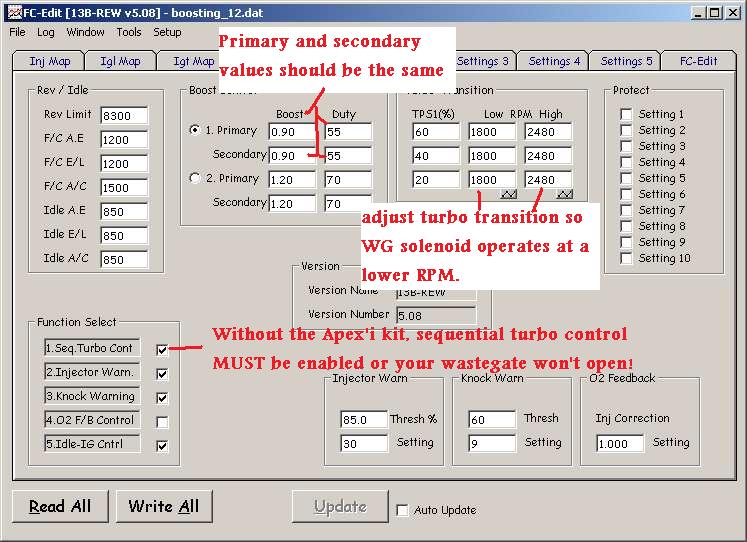
Get into your Datalogit settings 1 screen. Make sure "sequential turbo control" is checked. Set "turbo transition low" values to about 2000 and "turbo transition high" values to about 2500. Under boost option 1 (or 2 if you want to use 2), set both Primary and Secondary values to a value near what you want the car to run at in terms of target boost. Set both duty values to a low number like 20%. Do repeated pulls and increase both duty values until your logged PFC boost levels operate within an acceptable range according to your personal preferences, and does not drop off up top. If you have to, adjust target boost up or down in .05 kg/cm^2 increments and see if that helps along with more duty adjustments. The PFC does not know what your Autometer gauge is reading so don't focus on that so much.
Also, keep in mind that the default MAP sensor calibration is inaccurate and tends to read lower than external gauges, but this calibration can be changed with the Datalogit. I am running a GM 3 bar MAP sensor set in the Datalogit to scale 6630 offset 0 per Banzai Racing. My altitude is about 300 feet above sea level. One more accurate calibration I have seen for the stock MAP sensor is scale 5375 offset 3900 (thanks to Chuck Westbrook. PM cewrx7r1 about tuning notes). Any changes to the MAP sensor calibration may affect your tune, be warned.
Preface
This boost control setup is deep into the testing phase as a personal project of mine, but I'm not about to guarantee any results to anyone. Nor would I exhort anyone here to drop a perfectly functioning boost control setup and try something that some guy on the internet (me) did. The two things that made me pursue this project were 1) a desire for a clean interior with as little aftermarket electronics as possible and 2) heavy research into the factory boost control system and significant testing with the PFC on a car with sequential twins.
Introduction: Boost control as a system, not a specific device
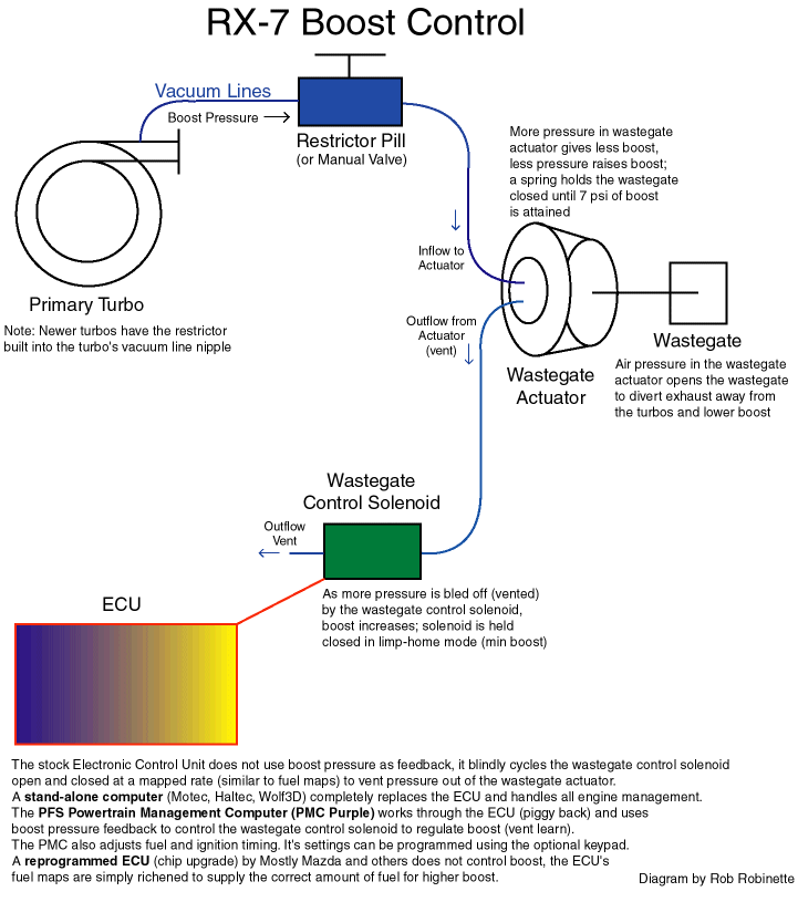
https://www.rx7club.com/3rd-generation-specific-1993-2002-16/why-engine-so-damn-complicated-part-1-sequential-turbos-demystified-841821/ discusses the sequential boost control system
I've heard on here that the factory FD boost control system sucks. While I am not here to defend a factory boost control system in a modified car, I would like to pose a question: does a boost control system (stock or otherwise) suck, or are some aspects of the system improper or insufficient for the intended goal?
What I will be doing here is breaking down the factory boost control system (detailed discussion in the thread above), a hypothetical externally wastegated boost system, and the Power FC control logic into their respective components in order to re-engineer a new (again I use the term) system. So far on my specific car at least it seems capable of accomplishing the same goal as buying a Profec and just following the instructions.
The Plumbing
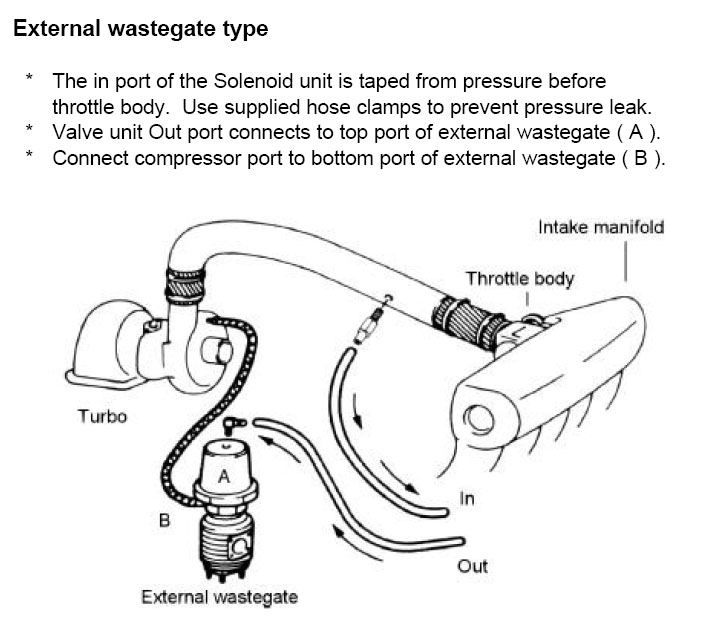
Here's a quick background on how an external wastegate works.
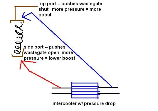
This diagram is to illustrate the principle of operation only. There are a couple different ways to hook up an external wastegate and you should never run an uninterrupted pressure source to the top port. The side port functions like an internal wastegate. The more pressure it sees, the more it's going to push on the spring to open. The spring will progressively open at some level of pressure and be fully open somewhere near the wastegate's rated spring pressure.
In our illustrative diagram, the purpose of an electronic boost controller is to regulate the pressure on the top of the spring by being hooked in-line with the hose. The pressure is regulated by cycling the boost control solenoid open and closed over a given period of time, like rapidly flipping a light switch on and off. The faster you flip the light switch (or the longer you keep it on when you flip the switch up), the more it looks like the room is illuminated. The same principle applies to a duty controlled solenoid valve, where a more "illuminated' room corresponds to more air passing through the solenoid with a resulting increase in boost. The factory boost control solenoid is an NC type--Normally Closed valve, and when 12v is applied to the coil inside it opens so that pressurized air may pass through. From the factory, this solenoid is hooked up after an internal wastegate actuator to regulate pressure leaving the chamber as a vent. Here, we are hooking it up before the external wastegate to regulate pressure entering the chamber.
When pressure builds up in that top port of the wastegate it will need to be relieved, or the wastegate will stay shut. Aftermarket solenoids have this relief function built in. Since we are using a factory solenoid with no built-in pressure relief, we need to build our own vent. The more air we vent from this line to the top port, the less you will be able to increase the boost over the rated spring pressure. I chose a small 1/8" vent based on my conclusions from a series of pressure tests with an air compressor and a pressure gauge. You can recirculate this vent to the intake if you want to.
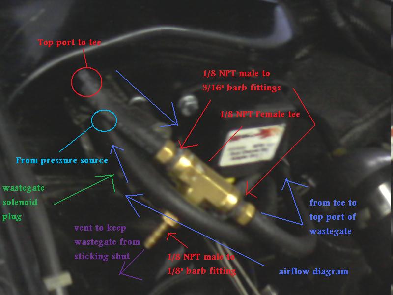
This is actually on a 2nd gen series 4 turbo II, so I had to source a precontrol/wastegate assembly (with plugs) and some FD harness pins (thanks Banzai Racing) to make it work. I tested both solenoids and then cut the solenoid assembly bracket in half so I would be using only one. The precontrol and wastegate solenoids appear to be the same in their operation. I mounted one to a factory 2nd gen bolt hole on the passenger side strut tower and just kept the other solenoid. These solenoids seem to have a low failure rate so I wasn't worried about them. You need to make sure the pressure source goes to the bottom inlet port on the solenoid (closer to the electrical plug) and the top port on the solenoid is used as an outlet. If the top port is used as an inlet, the bottom port will open/leak at about 6psi and we don't want that.
There is some debate as to where the pressure source(s) should come from. Consider this decision matrix, which for our purposes assumes all other aspects of the boost control system are held constant:
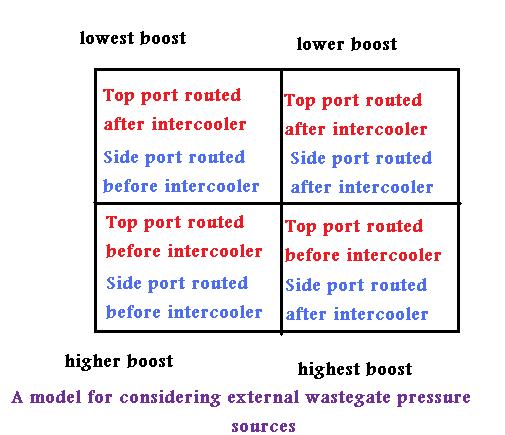
To understand this diagram, remember the pressure drop after the intercooler, and remember that as a general principle: with all other things held constant, the more pressure the top port sees the higher the boost will be. The more pressure the side port sees the lower boost will be, but no lower than the rated spring pressure.
I haven't tested all these combinations personally, but I suspect that the "higher boost" configurations require less duty cycle to maintain a particular manifold pressure and vice versa. But this is theory more than anything else, a model to improve our understanding. As I keep saying, boost control must be considered as a complete system so no results are ever guaranteed. One routing configuration isn't necessarily "better" than the others--it depends on your goals and the rest of your setup, such as your intended boost level, your wastegate spring, and the flow capability of your wastegate and wastegate runners. I am personally running the "higher" configuration presented here just because it made plumbing more convenient for me.
Non-sequential twins plumbing
I did mention non sequential cars in the thread title. I haven't personally tried this, but I don't see why you couldn't leave the stock wastegate solenoid connected and still control boost with the Power FC. Remove the restrictor pill on the inlet side to the wastegate. Hook the other end of the wastegate actuator to the bottom port of the wastegate solenoid, and either vent the top port or recirculate it to the air intake. There are no brass tee's involved here. I can give more detailed technical reasons why I think this would work if someone is interested. Otherwise all the tuning etc should be similar in principle as if you were doing the single turbo setup I have been describing (so leave sequential turbo control on in the PFC etc).
Boost control tuning and Datalogit settings
Remember that 1.0 kg/cm^2 is 14.22 psi.
The PFC boost control logic is a feedback system, just like an O2 sensor is part of the fuel feedback system. The target boost value is like the 14.7:1 target AFR in closed-loop fuel feedback, while the base boost duty setting is like an injector pulsewidth value in a fuel map before it has been corrected by O2 feedback.
Clarification: the boost is not "controlled" exclusively by the duty setting. Nor is the boost "controlled" exclusively by the target boost value. Solenoid duty varies according to these two settings and a number of logic parameters that we cannot change. The resulting boost curve depends on the way the solenoid is behaving (according to the control logic) and the mechanical aspects of the system such as wastegate spring pressure and wastegate flow capability.
Now, on to the Datalogit stuff. We are going to tell the PFC that we still have sequential twins hooked up so that the wastegate control logic still works and we don't have to buy that Apex'i kit if we don't want to. I haven't used the boost control kit, but it does include a 3 bar MAP sensor. You can use the stock one as I mentioned in the opening section, but unless you change the calibration your PFC boost will read a bit lower than external gauges.
Now that I have discussed the plumbing and Datalogit settings, I would like to briefly go into the tuning I have been experimenting with. I've mentioned in other threads that I think the PFC boost control settings and logic are poorly documented and poorly understood. What I have done in my testing so far is demonstrate that the PFC can dynamically adjust wastegate duty to hone-in on the target boost level, at least to a point. These are not logs from controlled tests on a loading dyno; I don't have that luxury, sorry. It's more of a proof-of-concept thing based on street tuning.
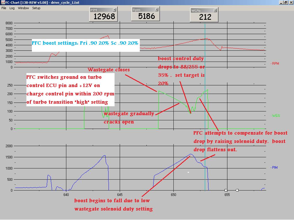
Here is a part-throttle pull with 20% duty. The boost falls off significantly up top:
Here is a part-throttle pull with 55% duty, boost target is the same. The boost drops off much less up top, about 5.5%. I am still playing around with the settings for further improvement.
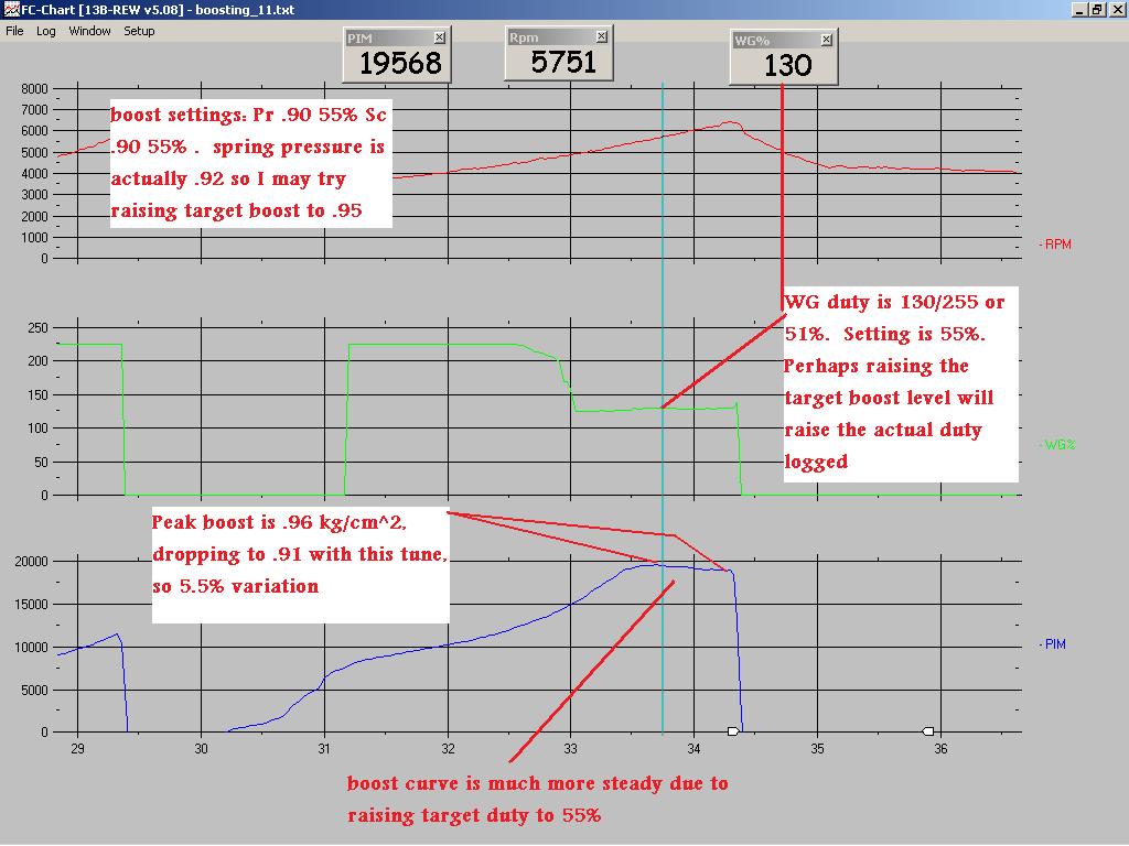
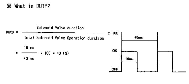
I would like boost to fluctuate within 2-3% of the target, IMO you can't really ask for much better than that. I really like being able to log wastegate duty so I can see exactly what my boost controller is doing. It is the parameter "Advance WG%" in the Datalogit. The logged units are not in %. They are out of 255 for some reason, so 125/255 = 50% duty. So when you are tuning, set a target boost level, and do multiple pulls. On each pull you should check your logs to see if the boost is dropping off. Continue to raise the duty values in small increments until the boost stops dropping, but if you go too far it may do the opposite and the boost will rise too high. Adjusting the target boost level appears to have some effect on how quickly the PFC changes the duty cycle values.
Conclusion
This is still in the testing phase. But so far I have concluded:
1) the boost control kit is not needed if you know what you're doing and you have a Datalogit
2) the PFC can intelligently adjust solenoid behavior to reach a target boost level. The jury is still out on how consistent the boost can be.
I will need more tests. Right now my target boost is so close to my spring pressure that it may be affecting things. Once I get more miles on my motor I plan to turn the boost up to maybe 16-17psi depending on how safe the temperatures seem. Then I will get further insight on just how precise the PFC can be.
Based on my recent experiments on a street ported car with a T04R and 13psi wastegate spring: If you want the Power FC to control boost somewhat like the expensive Apex'i boost control kit for single turbo cars (which I've never used and seems to be poorly documented), you need the factory wastegate solenoid still plugged in (use the WASTEGATE harness plug, not the precontrol plug). You also need $10 in hardware store plumbing fittings, some vacuum hose, and a Datalogit.
First, run a line from the side port of the wastegate to a pressure source (I prefer braided line for this port). Now run a pressure source to the bottom nipple of the factory wastegate solenoid. Run a line from the top port of the wastegate solenoid to a 1/8 NPT female tee. Two parts of the tee should be 1/8 NPT male ---> 3/16" barb. Those two will have hoses attached to them. One 3/16" barb has a hose from the solenoid to the tee and one 3/16" barb has a hose from the tee to the top port of the wastegate. The 3rd part of the tee is a 1/8 NPT male --> 1/8" barb to vent pressure from the top chamber of the wastegate so your wastegate doesn't stick shut.
Get into your Datalogit settings 1 screen. Make sure "sequential turbo control" is checked. Set "turbo transition low" values to about 2000 and "turbo transition high" values to about 2500. Under boost option 1 (or 2 if you want to use 2), set both Primary and Secondary values to a value near what you want the car to run at in terms of target boost. Set both duty values to a low number like 20%. Do repeated pulls and increase both duty values until your logged PFC boost levels operate within an acceptable range according to your personal preferences, and does not drop off up top. If you have to, adjust target boost up or down in .05 kg/cm^2 increments and see if that helps along with more duty adjustments. The PFC does not know what your Autometer gauge is reading so don't focus on that so much.
Also, keep in mind that the default MAP sensor calibration is inaccurate and tends to read lower than external gauges, but this calibration can be changed with the Datalogit. I am running a GM 3 bar MAP sensor set in the Datalogit to scale 6630 offset 0 per Banzai Racing. My altitude is about 300 feet above sea level. One more accurate calibration I have seen for the stock MAP sensor is scale 5375 offset 3900 (thanks to Chuck Westbrook. PM cewrx7r1 about tuning notes). Any changes to the MAP sensor calibration may affect your tune, be warned.
Preface
This boost control setup is deep into the testing phase as a personal project of mine, but I'm not about to guarantee any results to anyone. Nor would I exhort anyone here to drop a perfectly functioning boost control setup and try something that some guy on the internet (me) did. The two things that made me pursue this project were 1) a desire for a clean interior with as little aftermarket electronics as possible and 2) heavy research into the factory boost control system and significant testing with the PFC on a car with sequential twins.
Introduction: Boost control as a system, not a specific device
https://www.rx7club.com/3rd-generation-specific-1993-2002-16/why-engine-so-damn-complicated-part-1-sequential-turbos-demystified-841821/ discusses the sequential boost control system
I've heard on here that the factory FD boost control system sucks. While I am not here to defend a factory boost control system in a modified car, I would like to pose a question: does a boost control system (stock or otherwise) suck, or are some aspects of the system improper or insufficient for the intended goal?
What I will be doing here is breaking down the factory boost control system (detailed discussion in the thread above), a hypothetical externally wastegated boost system, and the Power FC control logic into their respective components in order to re-engineer a new (again I use the term) system. So far on my specific car at least it seems capable of accomplishing the same goal as buying a Profec and just following the instructions.
The Plumbing
Here's a quick background on how an external wastegate works.
This diagram is to illustrate the principle of operation only. There are a couple different ways to hook up an external wastegate and you should never run an uninterrupted pressure source to the top port. The side port functions like an internal wastegate. The more pressure it sees, the more it's going to push on the spring to open. The spring will progressively open at some level of pressure and be fully open somewhere near the wastegate's rated spring pressure.
In our illustrative diagram, the purpose of an electronic boost controller is to regulate the pressure on the top of the spring by being hooked in-line with the hose. The pressure is regulated by cycling the boost control solenoid open and closed over a given period of time, like rapidly flipping a light switch on and off. The faster you flip the light switch (or the longer you keep it on when you flip the switch up), the more it looks like the room is illuminated. The same principle applies to a duty controlled solenoid valve, where a more "illuminated' room corresponds to more air passing through the solenoid with a resulting increase in boost. The factory boost control solenoid is an NC type--Normally Closed valve, and when 12v is applied to the coil inside it opens so that pressurized air may pass through. From the factory, this solenoid is hooked up after an internal wastegate actuator to regulate pressure leaving the chamber as a vent. Here, we are hooking it up before the external wastegate to regulate pressure entering the chamber.
When pressure builds up in that top port of the wastegate it will need to be relieved, or the wastegate will stay shut. Aftermarket solenoids have this relief function built in. Since we are using a factory solenoid with no built-in pressure relief, we need to build our own vent. The more air we vent from this line to the top port, the less you will be able to increase the boost over the rated spring pressure. I chose a small 1/8" vent based on my conclusions from a series of pressure tests with an air compressor and a pressure gauge. You can recirculate this vent to the intake if you want to.
This is actually on a 2nd gen series 4 turbo II, so I had to source a precontrol/wastegate assembly (with plugs) and some FD harness pins (thanks Banzai Racing) to make it work. I tested both solenoids and then cut the solenoid assembly bracket in half so I would be using only one. The precontrol and wastegate solenoids appear to be the same in their operation. I mounted one to a factory 2nd gen bolt hole on the passenger side strut tower and just kept the other solenoid. These solenoids seem to have a low failure rate so I wasn't worried about them. You need to make sure the pressure source goes to the bottom inlet port on the solenoid (closer to the electrical plug) and the top port on the solenoid is used as an outlet. If the top port is used as an inlet, the bottom port will open/leak at about 6psi and we don't want that.
There is some debate as to where the pressure source(s) should come from. Consider this decision matrix, which for our purposes assumes all other aspects of the boost control system are held constant:
To understand this diagram, remember the pressure drop after the intercooler, and remember that as a general principle: with all other things held constant, the more pressure the top port sees the higher the boost will be. The more pressure the side port sees the lower boost will be, but no lower than the rated spring pressure.
I haven't tested all these combinations personally, but I suspect that the "higher boost" configurations require less duty cycle to maintain a particular manifold pressure and vice versa. But this is theory more than anything else, a model to improve our understanding. As I keep saying, boost control must be considered as a complete system so no results are ever guaranteed. One routing configuration isn't necessarily "better" than the others--it depends on your goals and the rest of your setup, such as your intended boost level, your wastegate spring, and the flow capability of your wastegate and wastegate runners. I am personally running the "higher" configuration presented here just because it made plumbing more convenient for me.
Non-sequential twins plumbing
I did mention non sequential cars in the thread title. I haven't personally tried this, but I don't see why you couldn't leave the stock wastegate solenoid connected and still control boost with the Power FC. Remove the restrictor pill on the inlet side to the wastegate. Hook the other end of the wastegate actuator to the bottom port of the wastegate solenoid, and either vent the top port or recirculate it to the air intake. There are no brass tee's involved here. I can give more detailed technical reasons why I think this would work if someone is interested. Otherwise all the tuning etc should be similar in principle as if you were doing the single turbo setup I have been describing (so leave sequential turbo control on in the PFC etc).
Boost control tuning and Datalogit settings
Remember that 1.0 kg/cm^2 is 14.22 psi.
The PFC boost control logic is a feedback system, just like an O2 sensor is part of the fuel feedback system. The target boost value is like the 14.7:1 target AFR in closed-loop fuel feedback, while the base boost duty setting is like an injector pulsewidth value in a fuel map before it has been corrected by O2 feedback.
Clarification: the boost is not "controlled" exclusively by the duty setting. Nor is the boost "controlled" exclusively by the target boost value. Solenoid duty varies according to these two settings and a number of logic parameters that we cannot change. The resulting boost curve depends on the way the solenoid is behaving (according to the control logic) and the mechanical aspects of the system such as wastegate spring pressure and wastegate flow capability.
Now, on to the Datalogit stuff. We are going to tell the PFC that we still have sequential twins hooked up so that the wastegate control logic still works and we don't have to buy that Apex'i kit if we don't want to. I haven't used the boost control kit, but it does include a 3 bar MAP sensor. You can use the stock one as I mentioned in the opening section, but unless you change the calibration your PFC boost will read a bit lower than external gauges.
Now that I have discussed the plumbing and Datalogit settings, I would like to briefly go into the tuning I have been experimenting with. I've mentioned in other threads that I think the PFC boost control settings and logic are poorly documented and poorly understood. What I have done in my testing so far is demonstrate that the PFC can dynamically adjust wastegate duty to hone-in on the target boost level, at least to a point. These are not logs from controlled tests on a loading dyno; I don't have that luxury, sorry. It's more of a proof-of-concept thing based on street tuning.
Here is a part-throttle pull with 20% duty. The boost falls off significantly up top:
Here is a part-throttle pull with 55% duty, boost target is the same. The boost drops off much less up top, about 5.5%. I am still playing around with the settings for further improvement.
I would like boost to fluctuate within 2-3% of the target, IMO you can't really ask for much better than that. I really like being able to log wastegate duty so I can see exactly what my boost controller is doing. It is the parameter "Advance WG%" in the Datalogit. The logged units are not in %. They are out of 255 for some reason, so 125/255 = 50% duty. So when you are tuning, set a target boost level, and do multiple pulls. On each pull you should check your logs to see if the boost is dropping off. Continue to raise the duty values in small increments until the boost stops dropping, but if you go too far it may do the opposite and the boost will rise too high. Adjusting the target boost level appears to have some effect on how quickly the PFC changes the duty cycle values.
Conclusion
This is still in the testing phase. But so far I have concluded:
1) the boost control kit is not needed if you know what you're doing and you have a Datalogit
2) the PFC can intelligently adjust solenoid behavior to reach a target boost level. The jury is still out on how consistent the boost can be.
I will need more tests. Right now my target boost is so close to my spring pressure that it may be affecting things. Once I get more miles on my motor I plan to turn the boost up to maybe 16-17psi depending on how safe the temperatures seem. Then I will get further insight on just how precise the PFC can be.
I did some pulls last night, this time with boost set to .95 kg/cm^2 and duty at 50% I think. Remember that my spring pressure is rated at about .93 kg/cm^2. This time Boost was a little higher at about 1.05 kg/cm^2, but boost dropoff was essentially eliminated and wastegate duty cycle was steady with the PFC only making very minor adjustments for the whole pull. On my car it seems best then to set the target boost level about .05-.10 kg/cm^2 lower than where I would like it to be.

hi,
very interesting thread. can you please describe what " duty " means?
as i see at the last graph at green wg there is a flat line at the bottom. sudenly there is a vertical liine to top and then horizontal again.
what does that means?the solenooid is open all the time and when the pim rises (past #31 at the pim graph) closes and start to develop preasure. then after a specific poin of preasure tyhe wg sol starts open again to drop the preasure?
also what "duty" means realy? the ecu drives the sol with a pulse of +12v or with fractions of +12v?
can you please describe what exactly the % duty means?
at the last pim graph the preasure is more steady as you state. if you do not use the pfc controled sol and use the mechanical system with a pressure reg and a hard spring , will you get better or worse pim graph?
i am questioning this because i am also trying to control my wg from the pfc but what is the point if the simple mechanical setup gives better results?
the ecu drives the sol with a pulse of +12v or with fractions of +12v?
The green flat line in the graph I posted is when the solenoid is not being pulsed at all. Therefore no pressure is pushing on the top of the spring to push the valve closed. In this case it is not pulsed under 2500 rpm because I have set the "sequential transition high" to 2500 rpm. You may be able to set it lower, but you would have to log "Sensor/SW TCN" and see if the PFC actually responds. I have a T04R on my car so it's not making much boost at 2500 rpm.
IMO pressure is only "needed" on the top port once the pressure from the side port of the wastegate is about to crack the valve open. Remember that in the two-port wastegate plumbing configuration we have two forces working against each other. On my old HKS 40mm wastegate with 10psi (.70 kg/cm^2) spring, I could hear the wastegate crack open at 6psi (~.42 kg/cm^2) if I had no boost controller installed. In that particular case it seems to me that if boost were under 6psi it wouldn't matter whether the top port of the wastegate receives pressure or not.
I hope that isn't too confusing, I'm trying my best here. The bottom line is, most single turbo cars aren't going to need wastegate solenoid duty (and therefore pressure applied to the top port of wastegate to keep it closed) at 2000 rpm. The exceptions would be cars that spool really really fast and maybe cars with a high flowing wastegate and a low boost spring.
if you do not use the pfc controled sol and use the mechanical system with a pressure reg and a hard spring , will you get better or worse pim graph?
For a lot of people, a manual boost controller may be "good enough." But most manual boost controllers require you to pop the hood and turn a **** every time to adjust it, which is annoying, and the really cheap ones aren't very precise to adjust. A lot of the cheaper ones have only one boost setting (versus 2 on the Power FC and many other controllers), which is also annoying. A self-correcting electronic system is a lot "better" in theory if it's set up right, especially since it can more easily adjust to changing weather conditions. But over time would you be able to feel the difference between that and a manual boost controller setup? The answer to that comes down to the driver and to the turbo setup itself. What is the spring pressure? How well does the manifold and wastegate control boost? How responsive is the turbo? I guess that's another vague answer, but I am always hesitant to give a 'yes' or 'no' on questions that are so debateable. And like always, a properly installed and adjusted manual boost controller beats an improperly set up electronic one.
I have some nice logs on my laptop from my latest couple runs. The boost was rock solid at 15psi or so. But the laptop is in the car, and I keep my car at a garage I am renting 15 minutes away so I don't have it at the moment.
Trending Topics
hi,
thanks for all the info!
as i understand from your example,at the mechanical wastegate control, the wastegate starts to open at the 6psi as you hear it. at the solenoid system, the wastegate kept closed until you hit the desired psi.correct?
i think that it is obvius that the electronic system is better and helps to develop pressure faster. right?
the duty at the pfc setup screen means that the solenoid will " work" from 100% down to the "settings " number ? that means that in no way the solenoid will kept "closed " for less % than the "setting" ?
on one graph the duty hits 35% and at the other 51% .both cases have lower limits.
first has 20% limit and hit 35%. after that the pfc tries to make corrections.
the second is 55% limmit. the pfc hits the 51% and NO more corections.
we do not want the pfc to make corrections?
also another interesting point is that the duty set % depends from your plumping and the bleed at the "T" AND the spring.right?
what if you want to change the boost sometime? you will need to change again the duty ?
Very good information here. I like reading things like this. If I had read this about a year ago I would set mine up like this rather then use the profec B.
I have a couple questions and comments. First under the "boost control" in the datalogit settings 1.... I'm guessing the PFC waits to adjust duty cycle of the solenoid until it reaches the target boost that is entered correct? and does the PFC monitor the boost level and adjust the duty cycle outside of what you enter? For instance if the boost was set to 1.00 and it dropped off to .50 will it stop controlling duty until it reaches the target boost level again?
With the profec B you have "set" which is what you set your boost at, then you have "Gain" which is the boost consistency, or how often the profec looks at the boost and makes adjustments. Then you have "Set gain" which is how long the gate is held open.
To compare the PFC boost control to the Profec II, it seems like "boost" is similar to "set" and "Duty" is similar to "Gain" And the set gain is just built into the PFC and has no real way to change it. Does this seem about right?
Another thing I wanted to mention is that if the boost level exceeds the "boost" setting in the datalogit by .25 bar it will induce fuel cut.
And lastly, there is supposed to be a way to hook a manual switch to the datalogit to toggle between boost settings 1 and 2 on the fly. If you look in settings 5 under FC box custom features, you will see enabled, Boost switch (SW4/AN8), and AN5-8 switch to ground.
Somehow you use these settings to wire in a switch to toggle between 1 and 2 boost control, which would be a pretty sweet way to switch between low and high boost. I'm not sure of the details but I'm sure it wouldn't take long to figure it out. I think it's supposed to momentarily make contact with ground to switch between.
Remember that the lower the duty value (less air to top port), the lower the boost, and the more the wastegate is open provided that enough pressure is going into the side port.
Something like that. It depends on the design of the manual boost controller you have and how it's set up.
If you are comparing an "ideal" manual boost controller setup to an "ideal" electronic boost control setup, both with "ideal" tuning, then the answer is yes. But when you start talking about an EBC on an undersized wastegate and crappy manifold vs. an MBC on a better setup, well it just depends. Remember that boost control is a system. That's why on a 100% stock car you have those restrictor pills but they all work together with the other parts of the system to control boost well.
I won't pretend to know all the logic contained within the PFC and I wish it were more adjustable. Like so many other things on this computer, we have to learn its quirks and work around them. But based on the logs I have so far, I have observed a few things about the boost control:
1) If the duty value is set way too low, you are going to see drastic corrections in duty as the PFC tries to correct for a loss of boost. In that log where I have it set to 20% duty, the PFC slowly ramps the duty value down (opens the wastegate slowly) to a minimum value. Using calculus it probably determined that the car was underboosting significantly, and thus the minimum value reached was 35%. As the boost started to fall off,
2) If an overboost occurs, the PFC will drop duty values. But it will only drop them so far--maybe 15% duty less than the target? This is something that people need to understand: there really is no such thing as a "set it and forget it" self-tuning system that doesn't need to operate within some kinds of parameters. Sorry I don't have any silver bullets for you, gentlemen. The factory closed-loop boost control system for example can adjust to the weather but it can't adjust to a huge change in the efficiency of the engine via modifications. That doesn't make it a "bad" or "dumb" system necessarily, it just makes it incompatible for certain purposes.
3) When the target boost and target duty are set decently in relation to the rest of the setup, the observed WG duty value seems to adjust only a couple percent and the boost hardly fluctuates--at least, in a given gear.
4) Once I raised the target boost from .90 to .95, boost seems to be going a little higher in the higher gears but it is still stable. I'm not sure if that only occurs on certain setups with certain combinations of "duty" and "boost" settings. But I have a T04R, which has a 67mm inducer wheel. That's closer to a GT40 in size, and larger turbos don't make as much boost in the lower gears. So maybe having an AVC-R would give me more adjustment with its gear-based duty settings. Or maybe further tuning of the settings will help this some. So far the boost pattern is still in the "good enough for me" range. My biggest goals were safe consistent boost and no external controller in the car to reduce clutter and wiring/vacuum routing. But every owner has his own goals and must make his own informed decision. No system is perfect and I'm not trying to hype anything here.
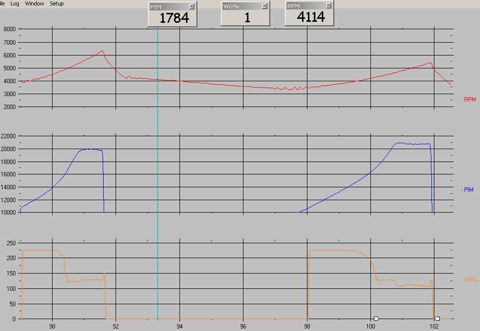
Here's a log I just snagged off my laptop. Settings are boost .95 and duty 50%. 2nd gear is on the left part and I think that's 3rd on the right. I didn't take it higher up in the rpms because the motor has less than 400 miles on it. Throttle was down about 2/3 of the way. Sorry that this isn't indicative of dyno conditions, I'm still testing remember. I notice that in 3rd gear the PFC dropped duty down to 42% to correct overboost some, while in 2nd gear a rock solid value near the 50% I targeted seemed to work. Maybe I should set my duty to 45%, and boost will even out between the gears more as the PFC can use smaller adjustments to keep everything in line as engine load changes.
Sure, just like the factory boost control system depends on the wastegate/precontrol inlet pills and spring pressure on the actuators. It all works together.
When I was testing to figure out what size vent i wanted, I used some plumbing fittings to connect an air compressor to the inlet of the tee I put in the picture. I put the other end of the tee to the top port of the wastegate like you see in the pic. First I ran a 1/4" barb vent and measured the maximum pressure that would reach the top port of the wastegate given the amount of air being bled out. It was maybe 2psi with the compressor continously supplying air through a tire inflator tool. Again, recall that an external wastegate works on a pressure difference. I figured that if I could only get 2psi to the top port at 100% duty I'd expect it to be pretty unresponsive as there wouldn't be enough pressure pushing the spring closed.
Then I tried a 3/16" vent. It would hold maybe 7psi max? Then I tried 1/8" barb. It was about 14. That seemed to allow a greater range for the boost controller. I also tried a setup with just a really really tiny hole drilled into a plumbing fitting as a vent, much smaller than 1/8". That would eventually vent all the pressure out when the solenoid stopped pulsing but the max pressure there seemed too high. I was worried it wasn't fast enough of a vent.
In the commander, there are two boost settings allowed. So for your low boost, pick option 1. Adjust the target boost and duty values until you are happy with it. Then go to option 2. Adjust the target boost and duty values until you are happy with that one. So yes you will have to tune both settings separately, but then you can switch between them quickly once you have them dialed in. Other EBC's are the same way.
look at this log again:
boost was dropping like a rock due to the low duty setting and the PFC made some big changes to the duty curve. It managed to slow down the boost loss significantly. But you are always better off with proper controller adjustments and correct plumbing.
I think that's... close, but the PFC is just basically a less adjustable AVC-R, and the AVC-R is not tuned in the same way a Profec is. "Boost" in the PFC is probably similar to "set" in terms of setting the target pressure. "Duty" comes straight from the AVC-R. You are commanding how much the solenoid is to cycle off and on, and you can't directly do that in a Profec.
In the PFC, I think the "Gain" and "Set gain" functions of the Profec are automatically adjusted based on both the "Boost" and "Duty" values and some other controller logic based on the observed boost pattern.
has anyone ever actually experienced this, despite what the PFC manual says? Because on my first outing, I did NOT have that whole vent installed because I didn't even think of it. My wastegate didn't open. Target boost was .90 and peak boost was 1.20 (17psi) and I didn't feel a damn thing. If it's anything like the overrev fuel cut, I would've known it was happening.
i think that it is obvious that the electronic system is better and helps to develop pressure faster. right?
the duty at the pfc setup screen means that the solenoid will " work" from 100% down to the "settings " number ? that means that in no way the solenoid will kept "closed " for less % than the "setting" ?
on one graph the duty hits 35% and at the other 51% .both cases have lower limits.
first has 20% limit and hit 35%. after that the pfc tries to make corrections.
the second is 55% limmit. the pfc hits the 51% and NO more corections.
we do not want the pfc to make corrections?
on one graph the duty hits 35% and at the other 51% .both cases have lower limits.
first has 20% limit and hit 35%. after that the pfc tries to make corrections.
the second is 55% limmit. the pfc hits the 51% and NO more corections.
we do not want the pfc to make corrections?
1) If the duty value is set way too low, you are going to see drastic corrections in duty as the PFC tries to correct for a loss of boost. In that log where I have it set to 20% duty, the PFC slowly ramps the duty value down (opens the wastegate slowly) to a minimum value. Using calculus it probably determined that the car was underboosting significantly, and thus the minimum value reached was 35%. As the boost started to fall off,
2) If an overboost occurs, the PFC will drop duty values. But it will only drop them so far--maybe 15% duty less than the target? This is something that people need to understand: there really is no such thing as a "set it and forget it" self-tuning system that doesn't need to operate within some kinds of parameters. Sorry I don't have any silver bullets for you, gentlemen. The factory closed-loop boost control system for example can adjust to the weather but it can't adjust to a huge change in the efficiency of the engine via modifications. That doesn't make it a "bad" or "dumb" system necessarily, it just makes it incompatible for certain purposes.
3) When the target boost and target duty are set decently in relation to the rest of the setup, the observed WG duty value seems to adjust only a couple percent and the boost hardly fluctuates--at least, in a given gear.
4) Once I raised the target boost from .90 to .95, boost seems to be going a little higher in the higher gears but it is still stable. I'm not sure if that only occurs on certain setups with certain combinations of "duty" and "boost" settings. But I have a T04R, which has a 67mm inducer wheel. That's closer to a GT40 in size, and larger turbos don't make as much boost in the lower gears. So maybe having an AVC-R would give me more adjustment with its gear-based duty settings. Or maybe further tuning of the settings will help this some. So far the boost pattern is still in the "good enough for me" range. My biggest goals were safe consistent boost and no external controller in the car to reduce clutter and wiring/vacuum routing. But every owner has his own goals and must make his own informed decision. No system is perfect and I'm not trying to hype anything here.
Here's a log I just snagged off my laptop. Settings are boost .95 and duty 50%. 2nd gear is on the left part and I think that's 3rd on the right. I didn't take it higher up in the rpms because the motor has less than 400 miles on it. Throttle was down about 2/3 of the way. Sorry that this isn't indicative of dyno conditions, I'm still testing remember. I notice that in 3rd gear the PFC dropped duty down to 42% to correct overboost some, while in 2nd gear a rock solid value near the 50% I targeted seemed to work. Maybe I should set my duty to 45%, and boost will even out between the gears more as the PFC can use smaller adjustments to keep everything in line as engine load changes.
also another interesting point is that the duty set % depends from your plumping and the bleed at the "T" AND the spring.right?
When I was testing to figure out what size vent i wanted, I used some plumbing fittings to connect an air compressor to the inlet of the tee I put in the picture. I put the other end of the tee to the top port of the wastegate like you see in the pic. First I ran a 1/4" barb vent and measured the maximum pressure that would reach the top port of the wastegate given the amount of air being bled out. It was maybe 2psi with the compressor continously supplying air through a tire inflator tool. Again, recall that an external wastegate works on a pressure difference. I figured that if I could only get 2psi to the top port at 100% duty I'd expect it to be pretty unresponsive as there wouldn't be enough pressure pushing the spring closed.
Then I tried a 3/16" vent. It would hold maybe 7psi max? Then I tried 1/8" barb. It was about 14. That seemed to allow a greater range for the boost controller. I also tried a setup with just a really really tiny hole drilled into a plumbing fitting as a vent, much smaller than 1/8". That would eventually vent all the pressure out when the solenoid stopped pulsing but the max pressure there seemed too high. I was worried it wasn't fast enough of a vent.
what if you want to change the boost sometime? you will need to change again the duty ?
Originally Posted by Dudemaaanownsanrx7
For instance if the boost was set to 1.00 and it dropped off to .50 will it stop controlling duty until it reaches the target boost level again?
boost was dropping like a rock due to the low duty setting and the PFC made some big changes to the duty curve. It managed to slow down the boost loss significantly. But you are always better off with proper controller adjustments and correct plumbing.
To compare the PFC boost control to the Profec II, it seems like "boost" is similar to "set" and "Duty" is similar to "Gain" And the set gain is just built into the PFC and has no real way to change it. Does this seem about right?
In the PFC, I think the "Gain" and "Set gain" functions of the Profec are automatically adjusted based on both the "Boost" and "Duty" values and some other controller logic based on the observed boost pattern.
Another thing I wanted to mention is that if the boost level exceeds the "boost" setting in the datalogit by .25 bar it will induce fuel cut.
Yes i experienced the fuel cut when i first set everything up i didn't adjust it. The boost went to a higher level then i expected. And had a very abprupt fuel cut, I changed it to a higher value and it didn't do it again. This wouldn't be an issue provided everything is set correctly and the wastgate line hasn't popped off.

so I finally went WOT on this thing now that the motor has a few more miles on it and I fixed a couple boost leaks. I did a 1st, 2nd, and 3rd gear pull on the street. Settings were .95 kg/cm^2 boost and 46% duty. I wasn't logging at the time, but peak boost values were
.95 (13.50psi) in 1st , only gave it 1/2 throttle to avoid wheelspin
1.05 (14.93 psi) in 2nd
1.07 (15.21 psi) in 3rd
So boost increased by 2% in 3rd gear. This is an acceptable tolerance for me. It is a larger turbo (T04R) and thus it will be particularly sensitive to the load differences in each gear.
So far I am happy with this setup. It is clean, simple, and low cost if you already have a Datalogit and your factory boost control solenoids. You just have to know what you're doing when you put it together and tune it.
After some extensive logging of my latest experiments with ISC-based idle control (you may see a thread on this soon), I made another log of a WOT 2nd gear pull but it somehow got corrupted.
But my latest settings are again back to .95 boost and 50% duty. Just using the Commander peak/hold function my WOT boost seems to peak in 2nd, 3rd, and 4th at 1.10 kg/cm^2 (15.5psi) with less fluctuation than before. Again 1st gear makes less boost (right near the specified target of .95 kg/cm^2) and breaks traction.
But my latest settings are again back to .95 boost and 50% duty. Just using the Commander peak/hold function my WOT boost seems to peak in 2nd, 3rd, and 4th at 1.10 kg/cm^2 (15.5psi) with less fluctuation than before. Again 1st gear makes less boost (right near the specified target of .95 kg/cm^2) and breaks traction.
you set it to 0.95 and see 1.10 only at the 4gear ? did you tryed to increase the duty?
i am thinking if this diference in boost is dangerus.
if you enlarge the bleeding and increase duty?
why thiss hapens only in 4gear? the engine sees the same load but longer time. thats why i am thinking if the bleeding is not enouth.
i am thinking if this diference in boost is dangerus.
if you enlarge the bleeding and increase duty?
why thiss hapens only in 4gear? the engine sees the same load but longer time. thats why i am thinking if the bleeding is not enouth.
i am thinking if this diference in boost is dangerus.
Remember that increasing duty results in a wastegate that is more closed, increasing boost over the rated spring pressure. That applies in either this configuration with the solenoid before the external wastegate, or on the stock sequential configuration with the solenoid venting out of the wastegate. In my setup, the factory wastegate solenoid is plumbed exactly like an aftermarket boost controller's solenoid would be on an external wastegate. There is no "venting" in this configuration to relieve pressure. That is only on the stock twins.
in your bigining of this thread you describe the canections:
"First, run a line from the side port of the wastegate to a pressure source (I prefer braided line for this port). Now run a pressure source to the bottom nipple of the factory wastegate solenoid. Run a line from the top port of the wastegate solenoid to a 1/8 NPT female tee. Two parts of the tee should be 1/8 NPT male ---> 3/16" barb. Those two will have hoses attached to them. One 3/16" barb has a hose from the solenoid to the tee and one 3/16" barb has a hose from the tee to the top port of the wastegate. The 3rd part of the tee is a 1/8 NPT male --> 1/8" barb to vent pressure from the top chamber of the wastegate so your wastegate doesn't stick shut."
there you refer to the vent niple. is this setup you describe the aftermarkets wastgates plumbing?
i do not know how the aftermarkets solenoid must connect at all.i thought that the aftermarket uses a vent like yours.i am confused...
Sorry if I have made this confusing in any way. The term "vent" has been used in two different ways. On my setup, the vent is used to keep the wastegate from sticking closed.
That diagram ^ is bascially how I have my car plumbed. The difference is, aftermarket solenoids have a vent built in to keep the top port of the wastegate from holding pressure. The OEM boost control solenoids need to be attached to that little brass tee there to recreate that function. If you hook up a stock boost control solenoid exactly like that diagram (without the brass tee) your wastegate will not open.
The vent function of the stock boost control system is completely different. The solenoid keeps pressure from building up in the internal wastegate in order to raise the boost.
Maybe modifying that diagram will clear things up.
Greddy Profec S plumbing would be:
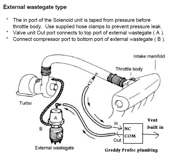
My setup using the factory wastegate solenoid:
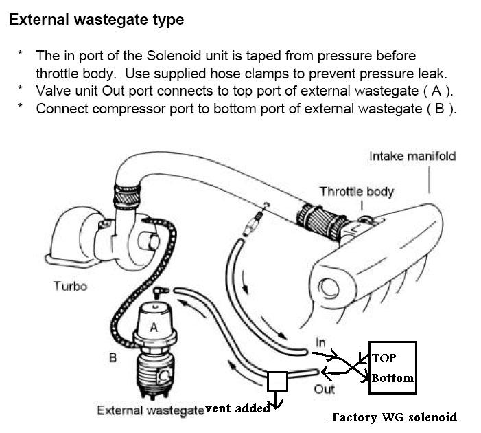
They're very similar.
Now compare that to the "vent" function of the factory wastegate solenoid, used in the factory sequential turbo system with internal wastegate. Don't get all this confused.
Greddy Profec S plumbing would be:
My setup using the factory wastegate solenoid:
They're very similar.
Now compare that to the "vent" function of the factory wastegate solenoid, used in the factory sequential turbo system with internal wastegate. Don't get all this confused.

you set it to 0.95 and see 1.10 only at the 4gear ? did you tryed to increase the duty?
i am thinking if this diference in boost is dangerus.
if you enlarge the bleeding and increase duty?
why thiss hapens only in 4gear? the engine sees the same load but longer time. thats why i am thinking if the bleeding is not enouth.
i am thinking if this diference in boost is dangerus.
if you enlarge the bleeding and increase duty?
why thiss hapens only in 4gear? the engine sees the same load but longer time. thats why i am thinking if the bleeding is not enouth.