When you click on links to various merchants on this site and make a purchase, this can result in this site earning a commission. Affiliate programs and affiliations include, but are not limited to, the eBay Partner Network.
Thank you for providing the additional feedback on the electrical contacts with the relays and connector. It may be tempting to remove the diode but still hold off until we verify that it is bad. Will you be testing the diode on another known Hyd Unit (on a friend's FD)? I know that you are excited to test the ABS light with a different instrument cluster for my Step 12. I too am looking forward to reading about your results.
BTW, the basis for that check comes from Pg P-54 and P-55 of the FSM. There are 2 charts: 1) Electrical diagnosis support Hydraulit Unit and 2) ABS Control Unit. Look at the bottom of each chart. You will see the Circuit "HU-ABS warning light" and "ABS CU-ABS warning light". The description for each Open and Short Circuit condition mirror one another. Specifically, we would check for a Short Circuit condition. Now that has me thinking about a missed opportunity!
While you wait for an instrument cluster to test and since your car has no cluster, we need to verify the wire going to the ABS light bulb has no shorts. Because this wire coming from the ABS CPU to the ABS Light Bulb in the instrument cluster is disconnected, it should read an Open Circuit. I believe we have not explored this option! This is the procedure I'd like you to follow before installing a surrogate cluster:
1. Instrument cluster removed, specifically Connector C1-01, "1" Series plug.
2. Disconnect Connector O-01 from the ABS CPU and Connector O-02 from the Hyd Unit.
3. Set the DMM to Resistance (Ohms)
3. Connect a DMM to the wire harness (loom) side of Connector O-01 Pin G/O. Use the Red (Positive) lead to this Pin.
4. Touch the Black (Negative) lead to chassis ground.
5. The measurement should be Infinite (Open), DMM may display "Ol" or "O/L" or something similar.
6. Remember to use a bare metal contact point for chassis ground.
7. If measurement reads 0 Ohms (short) then there could be a short circuit in Connectors X-10, X-06, X-18, or C1-01 ("1" series connector).
8. Refer to Pg Z-107 for Connector X-10 and Pg Z-45 for Connectors X-06, X-18, and C1-01 locations.
9. Repeat this procedure for Connector O-02 Pin G/O and chassis ground; result should be identical (open).
What were your results?
Cheers,
George
P.S. This note celebrates my 1,000 post! It took me 14yrs to reach this milestone. Hooray!
Hi George. I thought you were on to something there.. because there is the speedo mph converter soldered into the cluster wires. It might be worth just checking that the cluster connector itself is not permanent earth on the off chance it has been cut and joined somewhere. I doubt but you never know. Not sure how to work out which plug to go for as they all look similar?! As for your checks above the pins both read as open circuit as they should. So no cigar. But definitely worth ruling it out.
The car has a MPH converter attached to the wires? Could you share some photos of it? Please tell me more about that. How long has that device been connected to the car? Did the ABS light come on shortly after this mod was installed? Was there any other electrical work done to the car before the light came on? What instrument cluster are you using; is it stock with OEM gauges? Are there any modifications to the instrument cluster itself? Are you aware that the factory speedo can be converted between MPH & KPH? DaleClark has an excellent thread that covers that specific topic.
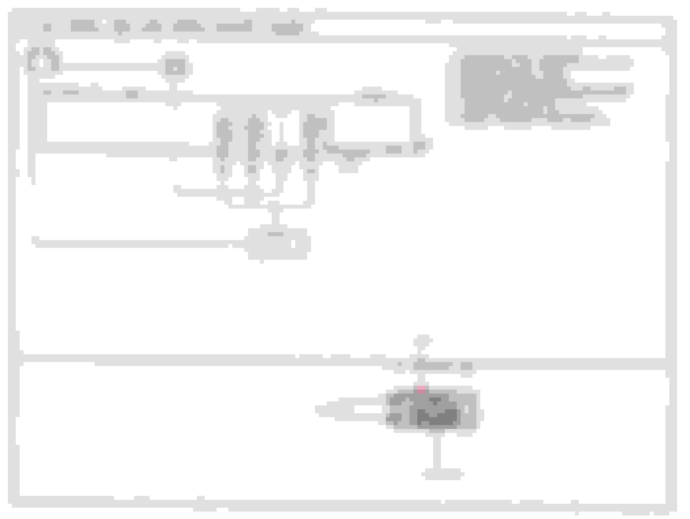
This was taken from the Wiring Diagram manual and it shows the differences between each plug for Connector C1-01. These connectors are designed to be "fool proof"; they are keyed to prevent inadvertent cross-connections. The highlighted plug shows the "1" series plug that I mentioned previously.
Note the specific keying of each plug on Connector C1-01
It was good to hear that the wiring in between the ABS CPU and ABS Light read an open circuit with both ends disconnected. That means there are no parallel paths to ground.
I also ask that you test one more variation of the ABS Light wiring. The reason for this next check is to verify the measurement of the diode when it is the only component connected in the circuit.
1. Instrument cluster removed, specifically Connector C1-01, "1" Series plug.
2. Reconnect Connector O-02 into the Hyd Unit.
3. Set the DMM to Resistance (Ohms)
4. Connect a DMM to the wire harness (loom) side of Connector O-01 Pin G/O. Use the Red (Positive) lead to this Pin.
5. Touch the Black (Negative) lead to chassis ground.
6. The measurement should be under 1 kOhms (1,000 Ohms; reading through diode).**
7. From your earlier measurements, the DMM may read 7.5 - 8 MegOhms because we are measuring resistance from the suspect diode.
8. Swap meter leads, that is use the Red (Positive) lead to chassis ground and use the Black (Negative) lead to Connector O-01 Pin G/O.
9. The measurement should be Infinite (Open), DMM may display "Ol" or "O/L" or something similar.
To be thorough, I'd also ask that you measure the resistance of the Stop Light Switch wiring from the Stop Light Switch (located on the brake pedal) to the ABS CPU.
To test, perform the following:
1. Disconnect Connector O-01.
2. Set the DMM to Resistance (Ohms)
3. Connect the DMM to the wire harness (loom) side of Connector O-01 Pin 1N. Use the Red (Positive) lead on this Pin.
4. Touch the Black (Negative) lead to chassis ground.
5. The measurement should be Infinite (Open), DMM may display "Ol", "O/L", or something similar.
6. Have an assistant step on the brake pedal. This engages the Stop Light Switch and closes its contacts.
7. The DMM should now read 0 Ohms (Short).
8. Have the assistant release the brake pedal. This disengages the Stop Light Switch and opens its contacts.
9. The DMM should return to Infinity (Open).
Right.. have more results! Thanks for the added info and checks. So I check the G/O pin on the cluster end and that is open which removes any earthing issue doubt. I also checked the resistance reading at the computer end for G/O and this is exactly as it is pump side. Just over 8 Mohms on my meter and then open. Consistent at least!
Now the brake switch test maybe threw up something.. with the pedal off I get a low ohms reading around 0.4ohms. With the the pedal pressed circuit goes to short. The other thing I noticed here which I am not sure if it is normal or not. Is the pedal appears permanent live? I.e with the ignition off, I pressed the pedal and the brake lights came on? Is that normal?
i have attached some pictures of my mph convertor below. I did not put this in so have no idea if the light came on after this or any other install sadly. It has been on since I got the car. I only found out recently the speedo can be converted internally. To be honest I am wary of pulling the converter back out in case I open a can of worms. The guy fixing my cluster has said he can do it and maybe come and do it later when he has time.
Also regarding the cluster it is a factory style set but has mazdaspeed clocks fitted. Again no idea when they were fitted or if light came on after?! Joys of inheriting someone else's work!
Pics posted separately.
Thank you for the feedback! I bet you will post the photos by the time I complete this post. Looking forward to seeing them!
Could you answer these specific questions to remove any doubt I may have:
1. Did you measure the 8MOhm and Open circuits as I described in Post #53, Items 6 and 9?
2. Where did you test the G/O wire - was it at the ABS CPU and Instrument Cluster or just the CPU?
3. Has the Stop Light switch ever been adjusted?
To answer your question about the tail lights, yes. They are supposed to be "live". With the key removed from the ignition and you step on the brake pedal the stop lights will illuminate. That is a safety feature.
The unusual measurement of the Stop Light switch does raise concern. It could mean it is out of adjustment, it failed internally, or there is a short along its wiring. This switch can be adjusted so I would argue that an adjustment may fix it. That 0.4ohms is basically a short without anyone pressing down on the brake pedal. That would mean your brake lights would illuminate. When you look at that switch, do you see a rubber stopper on the brake pedal? This stopper would be in front of the switch's plunger. If the adjustment does not work then remove the switch and test it outside of the circuit. Since it is a switch it will measure as an open when the plunger is pushed in or a short when the plunger is extended. There will be no in-between measurements.
To be thorough with the stop light switch, disconnect it and follow test procedures 1 through 5 in Post #54. If you measure anything other than an Open circuit then you have a problem with the stop light input to the ABS CPU. Remember, when you tested the brake switch (stop light switch), the ABS CPU was disconnected. Therefore, it would be possible for it to affect the ABS system but only when the car was moving. When the car is stationary then the stop light switch has little effect on the ABS system.
Thanks for posting the photos. Where do those external wires go? Where is the MPH converter - is it that box sitting on top of the steering column shroud?
I would recommend that the converter be removed and modify the speedo board using DaleCark's MPH conversion thread. This would reduce any other potential problem with your wiring looms. Additionally, the instrument cluster is out of the car now. Take advantage of that situation and use your friend's time wisely. Besides, the engineers incorporated that function into the speedo board so why not use it? The speedo board will automatically convert the odometer from km to mi too. I would recommend inspecting the speedo board before removing that converter though.
Replies to above.
1. Did you measure the 8MOhm and Open circuits as I described in Post #53, Items 6 and 9? Yes
2. Where did you test the G/O wire - was it at the ABS CPU and Instrument Cluster or just the CPU?
As per post #53 and additionally at the cluster with other plugs disconnected.
3. Has the Stop Light switch ever been adjusted? Not to my knowledge but recently replaced the master cylinder?
Will further test switch and report back.
Will also look at cluster wiring and talk to the guy about the conversion. He implied it was a quick fix.
The convert for mph is the blue heatshrinked item with the 4 wires coming out. None of the wires go to the plug with the abs light. I think there is power, ground and two signal wiresw
Thanks for all the advice and tips. It is a massive help and I would be lost without it.
You are more than welcome and thanks for the compliments!
The basics to convert a KPH speedo into a MPH speedo includes installing a diode on the component side of the board and moving 2 SMD resistors to adjacent solder posts on the trace side of the board. You may have to recalibrate your speedo afterwards, which Dale covered in that thread. Again, refer to DaleClark's thread for the specifics!
If I were in your shoes, I would remove the converter. Do you know what that board modifies? Does it only recalibrate the needle of the speedo? Or does it recalibrate the needle movement AND convert the odometer from km to mi?
I would bet dimes to donuts that your brake switch would have to be adjusted after you replaced the brake master cylinder.
Perhaps a visit to the pub would be in order after we fix your ABS problem? On a side note, I once visited Portsmouth in 2011. It was a good time! I enjoyed touring HMS VICTORY.
<div style="text-align:left;">Hi George, was out all day yesterday so just got to looking at this again now.. I thought we had found something but since rechecking as requested above and then looking at wiring diagrams I am now not sure. So I looked at the pedal and stop switch and could see this was completely shut when the pedal was off so not issue these. So ai unplugged the switch and took a reading on the switch itself. It read open with the pedal up and short with the pedal pressed. So all good switch side. Then I rechecked 1N at the abs plug end and brake pedal end. Got the same low resistance reading when earthed from each end. I measured across the two pins pedal end and this read as open. So all good from that point of view. So then I got online and found the FSM page for the stop light wiring . Thinking I had found an issue. The diagram as I understand shows that 1N is earth side of the pedal switch and completing an earth to the chassis. As such the stop light bulbs are in series on this earth wire so the low resistance reading I am seeing is in fact the meter earthing through the bulbs in the stop light? I tested a bulb in my spares box and do get a similar resistance reading across so believe that is that mystery solved and I am back to the drawing board. Still waiting on my cluster and getting quite frustrated as I was promised it latest today! That is one reason I did not want to ask about getting the speedo conversion done as well as I do not want to delay its return any further. <br />Side note.. the converter recalibrate the needle and the odometer.<br /><br />I will need more than a pint once I fix this.. if!? Will certainly send you one in the post though!<br />The historic dockyards in Portsmouth is very popular with visitors. We have taken the kids a few times. Plenty to see.</div>
I understand your frustration with the instrument cluster. I know we spoke about troubleshooting it before and it is unrelated to this topic. However, what type of repairs are being done to it? Bear in mind that solder repair to electronic boards are no simple task. Patience, skill, and steady hands are required.
Getting back on topic, the measurements you read at the stop light switch were indeed measuring the bulbs in the tail lights. I am glad that you checked the switch independently and got the proper measurements. Above all else, we verified the Stop Light Switch signal to the ABS CPU is good. That is one less item to worry about. When you tested the Stop Light switch at its connector, the meter was on the "positive" side of the bulbs. As the meter lead touched chassis ground (earth) then that completed the circuit through the bulbs.
I find that converter device interesting. However, since the car's speedometer has that function incorporated then I would do away with the unnecessary item. That is a problem to solve later though. Have you sourced a local Hyd Unit and tested it yet? I am very curious to learn about it. I still believe that will solve your problem. Is the Hyd Unit still installed in your FD? Did you remove any lines to the hyd unit when accessing the electronics tray?
Your head is in the game and I'm keeping score. My schematic is filled with notes so don't feel discouraged. We will fix this problem for certain! Especially when the reward is a pint or two. However, I would argue that some whiskey, bourbon, or scotch sounds even better. Maybe the next time I visit England we could celebrate and spare you the post?
A request to other members reading this thread: would you please provide data points on the ABS Hydraulic Unit's diode?
The steps to check the diode are: (Measurements taken on the Hyd Unit side of the connector)
--Disconnect Connector O-02 from the ABS Hyd Unit
--Black lead to Connector O-02 Pin G/Y and Red lead to Connector O-02 Pin G/O = 660 Ohms
--Black lead to Connector O-02 Pin G/O and Red lead to Connector O-02 Pin G/Y = Infinity (Open)
Completely unrelated: if you visit my area then you would be familiar with the names of surrounding cities, such as Norfolk, Suffolk, Portsmouth, Isle of Wight, etc... I wonder what influenced these names? LOL! If you enjoy history then you would certainly like Colonial Williamsburg.
Hi George, thanks for verifying my brake switch measurements.. I must have learned something along the way then! I won't lie I got quite excited about that odd measurement at first until I read the stoplight circuit diagram! So I am still waiting on measurements from a good unit. I have two sources. One is the guy with my cluster who has a brand new unit in a box plus a complete Japanese service manual which he thinks might have some extra troubleshooting info for abs. Also might have a spare diode! The other guy is a spare dealer I know of from the UK forums.. however neither have come through. Maybe someone here will see you post above and be kind enough to take some readings. Will certainly help see if we are on the right track there.Does it have to be a 1994 car or is 1994-1996 the same? I know earlier is possibly different. Cannot remember when it changed after.
As for drinks a nice whiksky or Bourbon suits me! I like my dark spirits! Portsmouth either side of the pond works! So all the places round you are named after South of England around me.. and you have an Isle of wight.. that's a new one on me.. I had heard of the others but not that!
I am sorry to hear that the 2 prospective leads have not panned out. You could desolder that diode but before you attempt it, could you describe the solder equipment you have? You may also check out my tips for soldering thread on the forum. When soldering installing the diode, either the new one or this same one it is important to follow the polarity of it. I believe this point was reinforced in the same soldering thread.
How did you remove the cover to the electronics section of the hyd unit? When I looked at mine, I couldn't remove the lid without removing any hyd lines.
At this point I'd like to offer a few more options for you to consider:
1. Remove the diode and test out of circuit. (A relatively easy task.)
2. Remove the Hyd Unit for additional inspections & testing.
2.a. Inspect the bottom side of all connectors & wires for any potential electrical arcs. A few people reported that any burned spots were hard to detect at first glance.
3. Test each Solenoid and valve individually. Each solenoid is physically connected to a hyd valve. Although the solenoid may measure good values, perhaps one of the valves is stuck? A stuck hyd valve could throw an ABS Light and is cause to rebuild/replace the Hyd Unit.
3.a. This type of test could be done without breaking hyd lines. However, you would need to apply +12V and return signals to each Solenoid, separately. When +12V is applied, you should hear it cycle.
3.b.This could be done using the car's battery. The danger to performing this type of test would be from electrical shock. I would also recommend using a 12W bulb with a socket to put in series with the positive lead from the battery. This bulb will act as a load to limit current to 1A. It is VERY important to note that 1A can kill a person! I'm not trying to discourage you from this test but you should be aware of any risks.
3.c. The math for this temporary circuit is straight forward: P=IE (Power of a component is equal to the input current multiplied by the input voltage).
P=12W, E=12V, then solve for I
P=IE
12W = I(12v)
12W/12V = I
1A = I
3.d. The importance of using an electrical load would prevent any damage to the Solenoid. It is basically a coil of wire and excessive current may damage it. The light bulb also acts as an indicator to a live circuit. If you are interested in this test setup, I recommend this connection setup: battery Positive post to Positive lead on 12W light bulb (socket). Then connect the Negative lead from the bulb socket to Connector O-02 Pin G/Y (Hyd Unit side). To complete the circuit, use a return wire from Connector O-02 Pin Y/G, Pin BR, or Pin B/W (Hyd Unit side) to the battery Negative post. Remember, only touch the return wire to one Pin at a time. You may want to cycle the power a few times so you may hear the solenoid click. If one doesn't click, cycle it a few times too. This may "unstick" the valve but avoid over cycling it. If the valve/solenoid doesn't click after 10 attempts then I would mark that solenoid as faulty. If this condition exists, you could rebuild it; another member has an excellent rebuild thread for the ABS Hyd Unit or you could replace the entire unit.
The important question to ask: What would you like to do?
thanks for the further Input and suggestions. First I would answer about my solder gear. Nothing special. I have generic units from eBay or local diy store. I have a small electric iron with a fine pointed end, a large electric iron with an end like a flat blade screwdriver and a gas iron with multiple ends and heat settings. I would be slightly worried about getting too much heat into the component and damaging that or the surrounding terminals .. that is my only concern. I will check your sioldering guide though. I probably need a solder sucker thingy?!<br />I have no intention of taking the complete unit out currently I will live with a light until next winter if need be! Removing and replacing the diode if seen fit is something I would have a crack at though. <br />I will try and cycle the solenoids if I can.. that sounds like a good illimination plan. I presume I can use a stand alone car battery? I have a circuit test light. So I could connect that to positive and probe the relevant pin, then use a wire to battery earth on the other pins? Lease confirm if polarity is important?<br />As for removing the cover on my pump.. yes it was rather tight.. I very carefully flexed a couple of the hardlines slightly and then in just the right spots I could wedge it out over the top of the relays by flexing the lock tab on the cover itself. I fully expected it to snap off.. and it may well yet! Pants design. Just a few more mm and it would come out fine! Just hope my lines don't spring a leak now!
Please take notes from my soldering thread. Using the right iron with the right amount of heat will help you immensely! Basically, a 40W iron, 0.032" solder, flux, and solder wick would get the job done. However, you may be constrained by space if you plan on working in the engine bay. Do a few dry-runs to make sure you wouldn't damage or melt anything when removing/installing the diode.
Remember, if the ABS Light is on that means the ABS system is not working properly. I am confident though that we will solve the problem!
To answer your questions:
1. Yes, you can use a stand alone car battery or remove your car's battery for use. Even a battery from a motorcycle or All Terrain Vehicle with +12V will work.
2. An automotive test probe may be used so long it is rated for 12v. Have your DMM standing by in case you want to measure the voltage drop across each solenoid.
3. Polarity makes a BIG difference when testing this circuit!
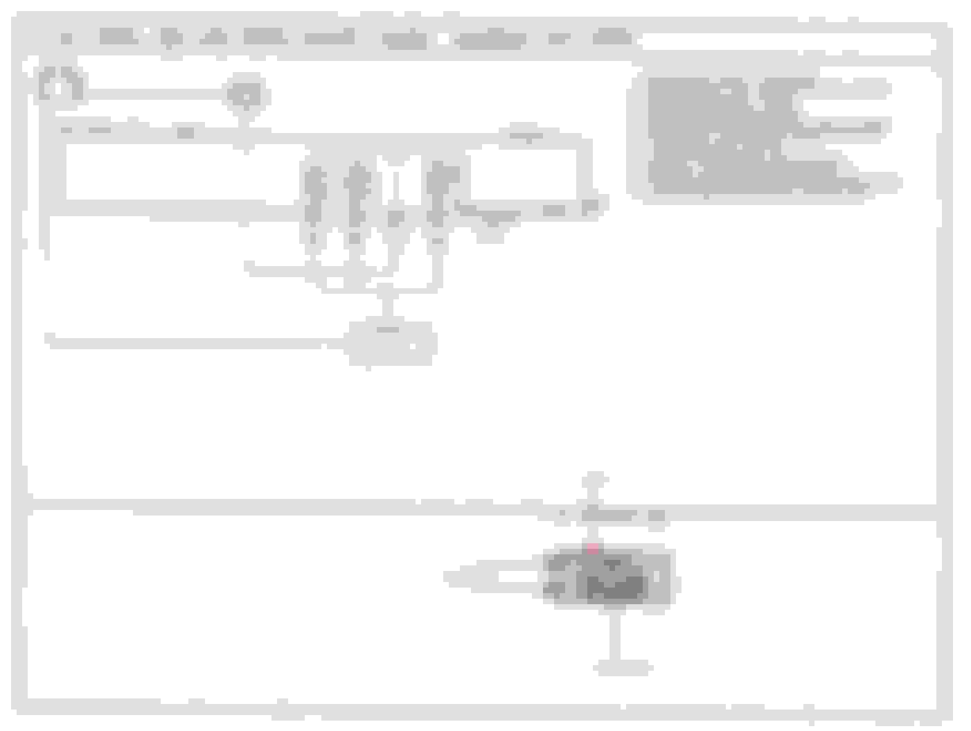
4. See schematic below for proper electrical connections to test each solenoid.
This schematic clarifies the connection of the light bulb in the circuit. The Positive lead of the bulb housing must be connected to the Positive terminal of the Battery. The Negative lead of the bulb housing must then be connected to the Hyd Unit Connector O-02 Pin G/Y. This arrangement maintains the proper polarity and reduces any confusion to connect wires.
Hhmmm.. this does not seem right.. I get a lit bulb off all the soelnoids but no clicking at all... I am assuming it should be quite audiable like a relay. Is that really likely they are all stuck. Could it be something I did incorrectly. Might explain why the diode failed as I gather they don't just usually fail for no reason?
Those are all good questions! I venture into the unknown as much as you when testing these solenoids. Simply put, I don't know! Typically, a solenoid makes a sound when it engages or disengages. Do you have an assistant who could place a hand atop the Hyd Unit? It could be possible that the click is inaudible but the movement of the solenoid could be felt. It would only click once per application of earth to the appropriate Pin. Did you cycle each solenoid by applying ground then removing it? You could also use an automotive stethoscope or long screw driver to detect sound in a localized area. There could also be the possibility of no/low fluid pressure in the system because a) no brake pedal is applied and/or b) the ABS Pump Motor is not allowing fluid pressure to build up inside the unit.
Since you didn't detect anything, you could potentially try reversing the polarity: apply +12V to Pins B/W, BR, and Y/G. Then connect ground (earth) from Pin G/Y to the Negative lead on the battery. The test probe should contact Pin G/Y. However, before doing this procedure try listening for the solenoids with a stethoscope or screw driver first.
To be clear, how did you connect earth from the schematic above? Are you using wire directly from the battery Negative terminal to the test probe then into the circuit? Or are you using a wire from the battery to chassis ground and then connect the probe from chassis ground into the circuit? Is the test battery fully charged and measures 12V?
Out of curiosity, have you called around to a few Mazda Service Departments and ask if they have an ABS tester for the FD? What about any RX-7 specialty shop? If you could get the exact tester from the FSM then it would answer all of our questions. According to my FSM, the Part # for the ABS Tester is 0000-42-0010 and a harness adapter may also be needed. That harness adapter part # is: 49 H066 033. They are found in Pg P-37 & P-38 of the FSM.
As for the diode, it could fail because of age or over-current. It is an avalanche diode so it is frequently exposed to high current (up to 15A) coming from the Solenoid Valve Relay. I still believe the diode is Suspect #1!
Went and tried again just now.. no helper but tried touching the pump, the bits that I think are the solenoids under the top of the pump and tried screwdriver in the ear trick. Also tried reversing polarity and pumping up the pedal... nothing! So maybe they are all stuck or the fluid damps the sound too much unless under brake pressure?! I had it connected direct from battery to the connector ... as per the schematic. My test probe being a length of wire with terminals each end.
I have made a post on the uk forum to see If anyone knows where there is a tester. I asked a couple of shops before with no joy.
Copy all. No noise detected from any solenoid, and reversed polarity proved similar results. Could you take a photo of your Hyd Unit and point out where you are attempting to listen to the solenoid energize/de-energize? Did your instrument cluster return? If not, when do you anticipate its arrival?
You could try to turn on the ABS Pump then test each Solenoid. This would be done by: creating a parallel path from the stand alone battery to the ABS Pump Motor. You must relocate the earth connector from the ABS Motor (connected to chassis ground) to the stand alone battery Negative terminal. Next, inject a +12V signal at Connector O-03 Pin R/Y (on the Hyd Unit). Then, touch the probe to each solenoid. You may have to use an assistant to press the brake pedal. It is important that your assistant applies firm and constant pressure on the brake pedal. Do NOT pump the brake pedal!
Are you testing this with the *engine running*? If you just turn the key to On and don't start the car the ABS light will stay on solid. The project car I'm working on I noticed that myself today and thought about this thread.
I think it's a bulb check for it to come on when you turn the key, then go out when the engine is running.
Thank you for asking and giving me a sanity check! That is not a dumb question. Yes, we already addressed that in Post #27. The solenoid tests that we are currently researching do not require the car to be running. The Hyd Unit is electrically disconnected from the car and a separate battery is used to inject a signal into each solenoid. These checks bypass the ABS CPU, Motor Relay, and Valve Relay.
Take a look at this post for an approximate location of the solenoids on the Hyd Unit. Rebuilding ABS Pump Post #21 It looks like the solenoid is at the base of the unit. Based upon your test results thus far, you may not be able to hear each solenoid actuate. However, if you turn on the pump and then actuate each solenoid then it may be possible to feel the brake pedal pulse. The brake pedal must be firmly pressed in order to feel any pulsations.