When you click on links to various merchants on this site and make a purchase, this can result in this site earning a commission. Affiliate programs and affiliations include, but are not limited to, the eBay Partner Network.
Hi George,
here is an update. I cannot do the last couple of checks as my cluster is away and I have had to give the one I borrowed temporarily back. I am hoping to get my cluster back this week but have been promised it for some time now! So thought I would just clarify the results up to now. Answers in red.
1. Did you find the 15A ABS fuse in your fuse box? Was it good? Not specifically so tested all fuses in the box. All good.
2. When you recorded the Wheel Speed Sensor resistance at 920 Ohms, was that at each sensor connector AND at Connector O-01?
--Basically, we are testing the wiring from the ABS CPU to each Wheel Speed Sensor as a whole and then separately. The Ohm readings given previously were from the O-01 plug. However I have previously tested the sensors. was the first thing I did and results were in the same region 950-1000ohms for all 4.
3. I may not have articulated this previously, but when you measure values for the ABS Hydraulic Unit components such as the ABS Motor, Motor Relay, Solenoids, etc... you should be taking measurements from the Hydraulic Unit side of the connector. This checks the electrical components of the Hydraulic Unit. Yes I understood that and confirm I took them pump side.
4. When you tested the diode on the Hydraulic Unit, did you observe the correct polarity with the meter leads? That is, Black (Neg) lead on Connector O-02 Pin B and Red (Pos) lead on Connector O-02 Pin G/O? Again, this is on the Hyd Unit side. This verifies the wiring through the diode and Solenoid Valve Relay. Yes
--The 8 Megohm resistance does seem unusually high when the diode is forward biased and open (infinite Ohms) when reversed biased. However, I am glad that you used the continuity function and recorded the voltage. Did you hear the tone "beep" one way and no tone when you swapped the leads? The diode test function on the meter is separate to the continuity function so does not beep.
5. I also made one oversight on this check: the FSM wants to test the diode between Connector O-02 Pin G/O (Red or Pos Lead) and Pin G/Y (Black or Neg lead).
--Please verify this measurement, if not done already.
--You should see identical measurements as you noted in Item 4. this was in fact in your previous request in the test all solenoids bit. Measured same as other pins.
6. Next, I ask that you verify the wiring from the Hyd Unit to the ABS CPU. So plug in Connector O-02 and leave Connector O-03 disconnected. At Connector O-01 check: Assuming my note for the last check is correct then all these check fine.
Connector O-01 Pin 1T to Pin AG = short (reading through ABS Motor Relay coil)
Connector O-01 Pin AG to Pin 1R = short (reading through Solenoid Valve Relay Coil)
Connector O-01 Pin 1C to Pin AB = short (reading through Solenoid L.F Coil)
Connector O-01 Pin AH to Pin AB = short (reading through Solenoid R.F. Coil)
Connector O-01 Pin AI to Pin AB = short (reading through Solenoid Rear Coil)
Connector O-01 Pin 1C (I think this should be AA??) to Connector O-03 Pin R/Y = short (reading straight through wires only)
7. Ground is Ground. However, there are some instances when testing the physical location of a ground point has significant value. As you took resistance measurements at the rear of the car, using the car's chassis as ground is acceptable.
8. Could you please specify what Wheel Speed Sensor Pins you checked for Open circuits and which ones measured 920 Ohms?
--This may be difficult however, please disconnect all wheel speed sensor connectors to verify the shields are isolated from the sensor wire.
--This is also the perfect time to inspect each wheel sensor connector for any corrosion or other abnormalities such as wire kinks.
--Ensure the outer shield is isolated from the inner shield on the front Sensor wires. Connector O-01 Pin 1G to Pin 1K = 977ohms
Connector O-01 Pin 1F to Pin 1U = 978ohms
Connector O-01 Pin 1Q to Pin 1O = 955ohms
Connector O-01 Pin 1P to Pin 1L = 1002ohms
At Left Front senor plug 977ohms, Right Front plug 0.978 ohms. To test the rears again at the plugs will be a major headache as I have a audio build in the rear seats! As stated above I remember these all test good and with same/similar readings to what I have at O-01 now. also the light has always been on so not a result of the audio build. I think hopefully the other tests done at the O-01 plug prove that out?
9. Reconnect Connectors O-02 and O-03, and all the Wheel Speed Sensor connectors (O-04, O-05, O-06, & O-07) after all other resistance measurements were recorded. Leave Connector O-01 disconnected. Set your DMM to V-AC (It may be represented with a "V" plus a Sine wave). I would like you to follow the checks in the FSM, Pg P-52, Step 3. Do this only when you verified the wiring from the Wheel Speed Sensors to the ABS CPU are good. You may also need a buddy to help spin each tire (tyre).
--Follow the chart in the FSM. You should see 50-60mV (that's millivolts) for each Wheel Speed Sensor. Did this last week and can confirm all in spec.
10. Verify that the Ground wires to the ABS CPU measure a short. Check at:
Connector O-01 Pin 1D to Ground = Short
Connector O-01 Pin 1S to Ground = Short
Connector O-01 Pin AF to Ground = Short All above are correct
11. Verify that the Ground wire to the Hyd Unit measures a short. Check at:
Connector O-02 Pin B to Ground = Short Yes
So nothing unusual to report still!! I can see your method don't worry.. Just working your way through top to bottom. I hope the last test turns up something!
Thank you for responding with all the above information. It was helpful! I also wish to correct a couple of errors that I made:
A. You are correct in reading resistance for Item 6. I should have asked to check:
--6. Connector O-01 Pin AA to Connector O-03 Pin R/Y = short (reading straight through wires only)
B. Reading the FSM and wiring diagram I was incorrect about isolating either the ABS CPU or ABS Hyd Unit in Item 12. In order to properly test the ABS warning light, the engine must be running. Otherwise, when the key is set to ON, the ABS light will always stay on. I observed this indication in my FD today. Throw out the old Item 12 test conditions and follow this new procedure:
--12. Reconnect all ABS system Connectors but leave Connector O-01 disconnected.
----Start the car and let the engine warm up. After 30 sec, does the ABS light illuminate with Connector O-01 disconnected?
----Shut off the car (engine not running). Reconnect Connector O-01 then disconnect Connector O-02.
----Start the car and let the engine warm up again (we don't want any potential flood situations). After 30 sec, does the ABS light extinguish with Connector O-02 disconnected?
Onto further testing...
C. I suspect that your ABS Hyd Unit is bad. The only anomaly thus far was the resistance measurement of the diode inside the Hyd Unit. You claimed that it measured 8 Megohms (forward biased) and Infinite Ohms (reversed biased). If you like, you may measure it again to be certain.
--On the Hyd Unit side connector, put the Black (Neg) lead on Connector O-02 Pin G/Y and Red (Pos) lead on Connector O-02 Pin G/O. This reads the diode in a forward biased condition. You should measure some resistance, roughly 100-900 Ohms. You should also have similar measurements from Connector O-02 Pin B (Black lead) to Connector O-02 Pin G/O (Red lead).
--Now, reverse the meter leads to the contacts. Black lead on Connector O-02 Pin G/O and Red lead on Connector O-02 Pin G/Y. This measures the reverse bias of the diode. You should measure Infinite ohms, aka an Open.
D. Earlier today, I performed the procedure in Step C. This was my result:
--Black lead to Connector O-02 Pin G/Y and Red lead to Connector O-02 Pin G/O = 660 Ohms
--Black lead to Connector O-02 Pin G/O and Red lead to Connector O-02 Pin G/Y = Infinity (Open)
E. Based upon the anomaly you recorded previously and my observation on a functioning ABS Hyd Unit, I propose that the diode in your Hyd Unit is the failure point. Would you be able to test this theory with another Hyd Unit? Do you have another nearby FD mate who could verify this measurement on his FD?
Leeroy, it helps that George did this kind of diagnosing for the military. He knows his stuff. If it's good enough for jet planes, it's good enough for the FD!
Hi George,
Thanks for the added info and confirmation of my results. I doubled checked my diode readings at the time. but happy to do it again. The strange thing was the test results in diode mode came back good? I will see if I can find another FD to make the same test with local to me. Won't be until the weekend though. Could the test be done on a pump unit that is out of the car? I could try a different multi-meter too I guess. As for running the car I cannot do that until the weekend either as I don't have enough time in the evenings before all the neighbours and kids are in bed! Is the diode something that can be replaced without removing the Hydraulic unit or does it mean pulling it out?
Take a look at this post, it sounds possible to replace the diode in the Hyd Unit but I do not know the specific part number to replace. The OP in that thread installed a "test" diode but still had unusual results. Ultimately, he found a broken pin at the connector, I presume O-02. Check it out here: How My ABS Failed
When testing another Hyd Unit, take a spare DMM to test the results with both meters. You could also do the same with your suspect Hyd Unit and a 2nd DMM. Additionally, that very high resistance you recorded may have passed on the equipment because enough current flowed when it was forward biased. You also got a good indication when the diode was reversed biased. For example, it read open. That means nearly all the current was shut off. Lastly, it is important to remember that all diodes are not perfect conductors, hence they are semi-conductors. They will allow a finite amount of current to leak through in a reverse biased condition and will offer some resistance when current flows in a forward biased condition.
I don't know how close you are to removing your ABS Hyd Unit but it would be interesting to see its electrical innards and inspect the wire harness (loom) to its electrical components. Maybe you may find some hidden damage to the connector as the OP found in the thread I provided earlier? When you are ready to begin that project, please take pictures and post! There is also an excellent thread on rebuilding/replacing the o-rings on the ABS Hyd Unit here: Rebuilding ABS Pump
Leeroy, it helps that George did this kind of diagnosing for the military. He knows his stuff. If it's good enough for jet planes, it's good enough for the FD!
I remember dreadimg over this same ABS issue. Checked everything. turns out it was the silly 10 amp rear wiper fuse that is under the driver side kick panel. Hope you find the issue because i know how annoying it can be
Hi George,
Thanks for that extra post.. I have found that one and I really cannot see anything wrong with the plugs. I am getting voltage going in from the car side. How can I easily check for voltage getting to the pump? It will be near on impossible to check the back side of the plugs on the unit with it in the car as there is not enough slack in the cable. Could I check for voltage feeding into the relay's inside the pump if take the cover off? I presume one of the switching terminals is always live with ignition on? Am I correct in thinking one live feed is into the pump assembly on the main 2 pin plug and the other live is back out to the ABS CPU? on the box plug? Or is there also live into the pump on that box plug? I am just thinking if I can check these voltages each side of the plug again maybe it will highlight something while I wait for my cluster to do step 12!
Okay.. so I took a look at the circuit diagram earlier and reckon that if I pull the relays out I can test for continuity between the 12v in terminals and then check the coil pins to the back of the car at the main O-01 plug. Would I be right? Might rule out a dodgy pin in the conception is all I am thinking. I guess I could also take a 12v reading at the relay pin to see if they are getting full voltage? Do you know which pins do what on the relays as I don't want to just poke around randomly. A pin out for the relays might help. The last one I found did not really seem to match my relays though?
Please refer to the FSM, Pg P-50 - P-51 to check the ABS Motor Relay, ABS Pump Motor, and ABS Valve Relay. Are these the relays you wish to check?
With regard to checking the wires to the ABS CPU from the Hyd Unit Relays, you already checked those and they measured good. Could I be mistaken?
Again, I suspect the diode in the Hyd Unit is bad. Let's focus on that unusual measurement before we chase other gremlins. I recommend that you check it against another Hyd Unit diode...or if another member reading this thread wishes to cross-check their Hyd Unit diode then please report your findings. The Hyd Unit does not need to be removed for these checks. However, if a solenoid is bad in the Hyd Unit, then it (Hyd Unit) must be removed for further inspection because each solenoid is physically attached to each hydraulic valve. That would entail a rebuild, which is also why I offered the rebuild link. If the diode is truly bad then the Hyd Unit would also need to be removed to inspect the electronics portion. Bear in mind, the Hyd Unit was not intended to be serviced so if it went bad then a Mazda Tech would remove & replace it.
The steps to check the diode are: (Measurements taken on the Hyd Unit side of the connector)
--Disconnect Connector O-02 from the ABS Hyd Unit
--Black lead to Connector O-02 Pin G/Y and Red lead to Connector O-02 Pin G/O = 660 Ohms
--Black lead to Connector O-02 Pin G/O and Red lead to Connector O-02 Pin G/Y = Infinity (Open)
I must also make one other correction about the ABS fuse. I don't know about any of you, but I seem to confuse the 10A Air Bag fuse in the fuse box (inside the cabin) with the 15A ABS fuse in the Relay & Fuse block (engine bay). My apologies to all if I created any confusion over these 2 fuses and systems!
For clarity, this is the 15A ABS fuse location:
Relay & Fuse Block, note the 2 fuses associated with ABS (Anti-Lock Brake System).
Thanks for correction.. If I have not already checked that 15 amp fuse I will do so again. I think I may have done so though. plus I have power at the Hydraulic unit plug which would imply fuses are good?
My other questions about checks for the relay was to verify if when the O-02 and O-03 plugs are connected I get voltage to the relays. i.e if the plug terminals were bad as the above post and David suggested before it might highlight this? I would imagine it is a 12v feed terminal if any that burns out? Would that be a fair assumption? I thought it would be a quick easy check (other than getting the plastic cover back off!!) while I wait to gain measurements from another unit or my cluster back to do step 12.
I got a spare multi-meter to use today and double checked my own readings last night which were the same. Hopefully I can update more this evening.
Just doing some additional reading/learning. Am I correct that pin 1V from the ABS CPU goes direct to the ABS warning light and splits to send power to the Diode? So if the light is always on 1V must always be powered when presumably it shouldn't be? So if the system is working I guess 1V is sending a signal which passes through all the solenoids back to the CPU and if good it switches 1V power output off and light goes out? hence the step 12 checks. I guess light should be out with O-01 unplugged and on with O-02 unplugged?
So diode is the suspected fault because it equates to the CPU test signal and if the diode is dudd the CPU does not get the right signal back? Think I have figured how and why the diode is there as well now! when the valve relay switches it stops the back flow of current coming from the 15amp ABS supply?
How did I do?!
Thank you
Lee
So I made some checks tonight by pulling out the relays from the pump and checking various voltage readings and continuity. All check fine. So a fault at the plug is seeming unlikely and diode is still hot favourite! You can clearly see the diode in the picture below and looks possible to get at with relays out. Just need a value for it. Has BYW5 printed on it. Maybe more text on the bottom. No doubt a part number. Just waiting on some backup measurements from a friend now. Oh and multimeter I borrowed gives similar results. 7.5Mohms.
My only explanation of the diode is this: The Hyd Unit diode serves as a high-speed one-way switch that is used to allow the ABS light to indicate a fault in either the Hyd Unit or CPU. The output of the ABS CPU Pin 1V is ground because this trace connects to the negative side of the ABS light at Point 64. In Diagram C-1b, the positive side of the ABS light is connected to +12V. When the ABS system is actively being used (commonly known as dynamic mode), the ABS light would also illuminate and solenoids pulsate the brakes when the wheel speed sensors detect unbalanced signals. This is also why the ABS light is on when the car is on a dyno. The rear wheels spin while the front wheels remain stationary. This condition tricks the ABS CPU into a fault because the brake is not being used. In a static mode, the CPU would monitor for faults, hence the ABS light is on when the car is on a dyno.
Nice photo of the Hyd Unit innards. Could you get a closer shot of the diode? The part number you cited is a partial number. I believe there is one more number that is hidden from the photo. My Google-fu skills determined this diode, which is known as an Avalanche Diode, is either BYW52, BYW53, BYW54, BYW55, or BYW56. Some of these diodes are available from Digikey so identifying the specific one would be very helpful.
It may also be a good idea to inspect the underside of that electronics tray. Maybe that's where some problems occur with pins frying?
The zoom in function was not helpful, unfortunately. I propose a different viewing angle and a magnifying lens maybe useful to reveal the obscured digit(s).
An additional photo may not be needed unless you seek confirmation of the obscured digit(s).
Are you able to see any other digits on the diode?
Leeroy - found this regarding wiring from the fuse to the ABS hydraulic unit. The info comes from a member that tested everything (like you) and found nothing wrong, including the diode:
(7) Started testing the wires from the fuse to the hydraulic unit. Found that if I wiggled the 12v wire between the connector and the unit, the voltage would fluctuate.
(8) Pulled that pin out of the connector. It is a square box female design and the spring side was totally missing. One edge of the male pin was very slightly burned.
(9) Pulled the same type of female pin out of a new unused connector in my parts bin and repaired the connector. Evidently that one pin was not real tight and over the years the extra resistance slowly burned it up until it failed.
Maybe use a mirror tool to see the last number(s) on the bottom? Or can you dremel out a bit of the black plastic to open up a space where you can see the numbers? My guess still is you have a wiring issue but I am by no means an expert at this stuff.
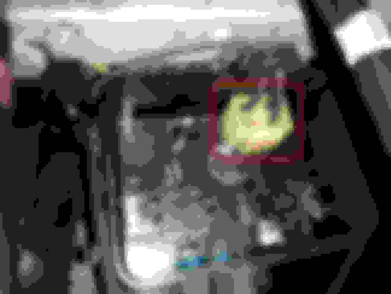
Have you removed this connector highlighted in red? Are you able to gain access to the bottom side of that tray? I am curious about the condition of those terminals that the connector and relays plug into. Maybe the diode is good but its terminals could be bad?
How do the terminals look underneath this connector?
Will try and look at that plug tomorrow. I assume that is an earth point? I cannot get at the underside of the electrics, just what you see. Then spades for the relays were all nice and clean and to be fair it all looks nice and dry and clean in there. No sign of corrosion anywhere from above. I took a reading the other day directly across the diode and in was the same as everywhere else.. so I assume if it was a dodgy connection the diode would have read less resistance which was my thinking?
Out of curiosity, has your Hyd Unit ever had a leak? Have you any luck with a mirror and flashlight to read any remaining digits on the diode? I think we should not discount the possibility of dodgy wiring under the electric tray if the diode does not fix the problem. The only way to inspect the underside would be to remove the Hyd Unit from the car. I think we should save that step until last. In the mean time, I'm interested to learn about the condition of that connector!
Just been and looked at this again. No chance of seeing anymore of the digits without taking the diode out. Which I am getting tempted to do.. once I can check the abs lights in step12 and rule anything out I will un-solder it and lift it out. Contacted a few places to see if they can supply all the numbers It might be. Just in case. Want to be sure I can replace it. I also pulled that off white plug out. As per other terminals they are all lovely and clean and look in perfect condition. So it is all back in waiting for my cluster now. About time the engine was run up too. Been a few weeks!
No leaks off the unit as far as I know. Not in my time with the car anyway.
 03-26-18, 07:08 AM