
DIY Solenoid Rack Tutorial

DIY Solenoid Rack Tutorial
I know I promised this a while ago and never got around to it. sorry =( but here you go!
Alright so I think everyone knows about the solenoids on our cars and the problems associated with them. So for a project for a quarter I decided to build a new solenoid rack to replace our stockers with something a little more...durable. so here you go. do this and you'll be a happy camper with your stock turbos. (until you get bored I guess)
This project is to replace the simplified sequential solenoids. If you haven't done simplified sequential then I would do that and make sure you have that working first before starting on this. No matter what you do, you should be sure that the only things not functioning are your solenoids themselves before doing this. But, preferably nothing at all is wrong
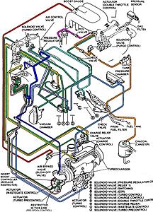
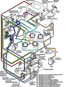
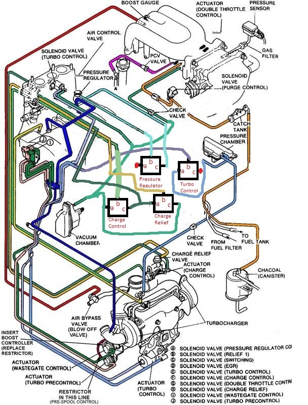
This setup replaces the following from this vacuum diagram:
Charge Control
Charge Relief
Turbo Control (3-way)
Pressure Regulator Control
Adjustments can be made to accommodate whatever solenoids you want to replace though. if you only want to do two of them then you can just do two. You might be able to squeeze five in the space by the ABS but it would be tight so try to limit it to four. I chose these four because the other 2 way turbo control solenoid has a heat shield on it, as well as the purge control solenoid, and these have been doing great for me.
Step 1:
Don't overthink this or over-complicate it. it's simple. so just don't.
and yes this is it's own step.
Step 2: Parts
Here is what you will need
4xFabco air 103SMG-2-V-M-12VDC directional control valves.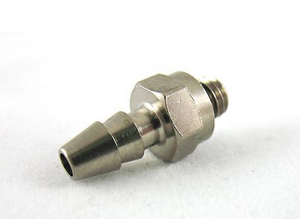
30 feet silicone vacuum hose 3mm ID 2x T-fittings (plastic works)
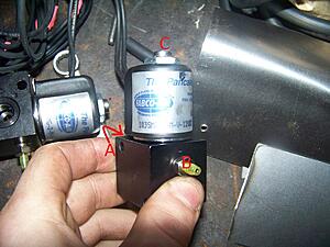
Ok so you've got your solenoids right? good down first thing you're gonna want to do is label the ports. just like the factory solenoids there is an A, B, and C. When it doesn't have 12 volts applied air flows between B and C. When it does have 12 volts applied air flows between A and B. so make sure you have these labeled. once these are labeled then you are ready to get this project going. Basically there is a front top and back port. your front port is B, top port is C, and back port is A. I have those sleeves over the barbs because I ordered too small of barbs on accident and didn't have time to get more so I just made do.
Step 4:The Rack
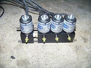
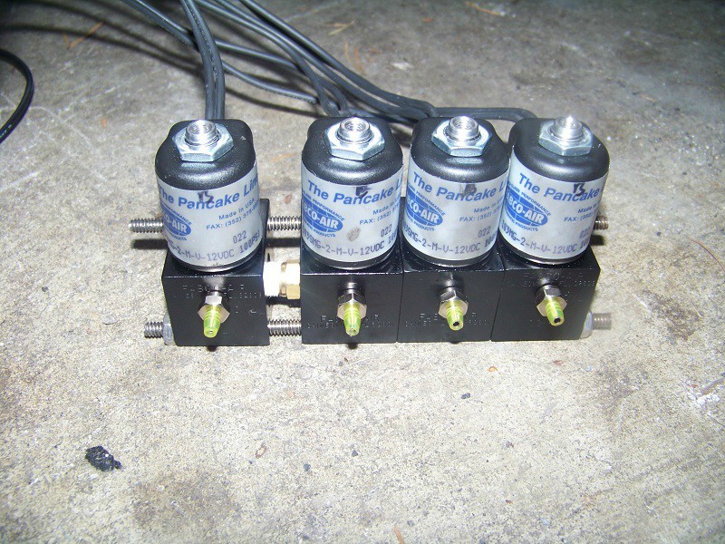
Ok cool so now you have your solenoids and fittings. Take your threaded rod and turn it into an actual rack that looks something like this minus the extra fittings because of my experimentation. Also note, ignore the b written at the top of each solenoid that is wrong. refer to step 3 for this. Also at this point label which solenoid will be which. I believe my order from left to right was CC,CR,TC,PR.
Step 5:Wiring
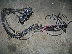
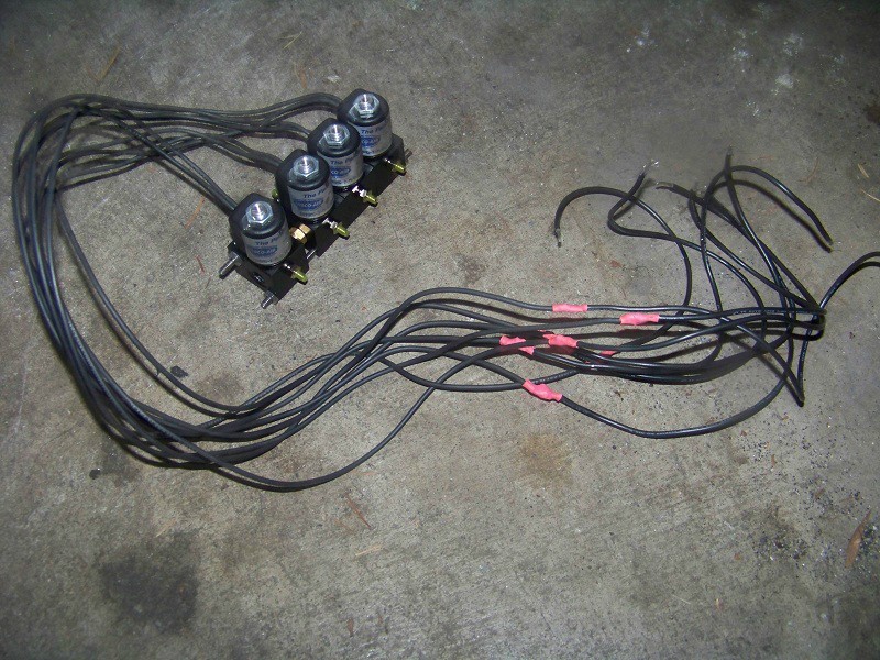
Set your solenoids to the left of the ABS module, and hold the wires along the firewall to see about how far you need to extend them to reach under the manifold. make them too long if you have to, but not too short! Then put the blade connectors on the end of each. I would also group each pair of wires together and label which solenoid it goes to so you don't lose them and forget later!(no blade connectors in the image but you get the idea)
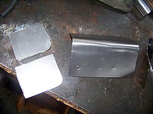
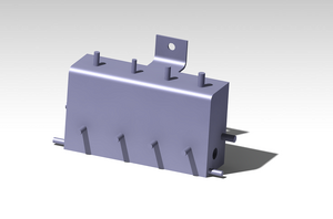
Step 6:Heat shield
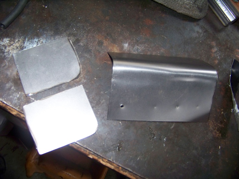
Ok this is kind of optional. I did it for my project because of the requirements I set beforehand. After taking temp readings I found it's not really necessary but it does make it look a lot cleaner. Mine is now painted black, and with a black heat shield and hoses this would look very clean and probably not even be noticeable to most people. My heat shield also doubled as a mounting bracket so if you don't make something like this you'll have to find a different way to mount the solenoids. I'm just gonna put up some pics of how i made it.
Step 7:Install
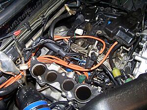
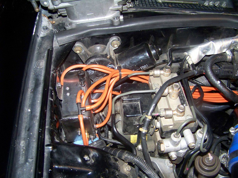
Ok you ready for this? alright. Take your intake manifold off and toss it to the side. see those electrical connectors next to the ABS module? unclip them from the chassis and push them down out of the way, since this is where the solenoid rack is going. Now set the rack down and start feeding the wire loom along the firewall. Zip tie it in place and you should be left with what looks like just another piece of wiring harness along the firewall.
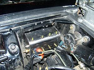
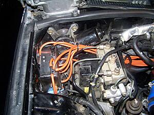
Ok cool you have a sweet looking solenoid rack that does nothing. Now, if you haven't done so already, disconnect and toss the old stock solenoids. say good riddance, burn them, stomp on them, stab them with a knife..whatever you please. Now don't forget which electrical connector goes to which solenoid because now you need to plug in the wiring. just take the two wires for each solenoid and attach them to the appropriate connector. it's just a 12V switched power so it doesn't matter + or - just plug them in. Mine were very secure, if yours is not a little electrical tape might be required. Sorry I don't have any great pictures of this but this is basically what you are looking for. and yes the orange hoses are as ugly as they look. I need to go get some black hose.
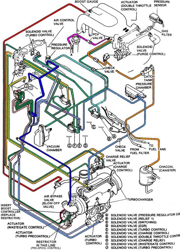
Now for the hoses. Here is the vacuum diagram you will be following. it is modified from the simplified sequential up at the top of this post.
Now as you can probably see the two t-fittings will be coming off of the charge control and charge relive solenoids. This helps minimize the number of hoses we have to run along the firewall. So attach the two t-fittings to begin with. Next I would start with the pressure control and turbo control. These each only have two lines coming off, the third is a dump port and can be left open, or you can put a snazzy little filter on it if you want. If anyone has input on why you absolutely should or should not let me know. Basically start with these because they are easy, you simply replace what was once there with longer hoses to the new solenoids. Just make sure you attach them to the proper ports and it's all smooth sailing.
Same goes for CC and CR though as you may have noticed, the hose system from the vacuum chamber still splits off in many places. This is where I decided to utilize the factory rats nest instead of having a billion T-fittings all over the place. it just makes it easier, and luckily there is one piece that has outputs for each of the four places it will need to attach. Basically you can utilize the rats nest however you want to accomplish your routing, just make sure that the two ports you think are connected are actually connected it can get confusing in there I know.
Alright so I think everyone knows about the solenoids on our cars and the problems associated with them. So for a project for a quarter I decided to build a new solenoid rack to replace our stockers with something a little more...durable. so here you go. do this and you'll be a happy camper with your stock turbos. (until you get bored I guess)
This project is to replace the simplified sequential solenoids. If you haven't done simplified sequential then I would do that and make sure you have that working first before starting on this. No matter what you do, you should be sure that the only things not functioning are your solenoids themselves before doing this. But, preferably nothing at all is wrong
This setup replaces the following from this vacuum diagram:
Charge Control
Charge Relief
Turbo Control (3-way)
Pressure Regulator Control
Adjustments can be made to accommodate whatever solenoids you want to replace though. if you only want to do two of them then you can just do two. You might be able to squeeze five in the space by the ABS but it would be tight so try to limit it to four. I chose these four because the other 2 way turbo control solenoid has a heat shield on it, as well as the purge control solenoid, and these have been doing great for me.
Step 1:
Don't overthink this or over-complicate it. it's simple. so just don't.
and yes this is it's own step.
Step 2: Parts
Here is what you will need
4xFabco air 103SMG-2-V-M-12VDC directional control valves.
These are your solenoids. if you hadn't guessed. They have three ports A, B, and C. I ordered two different types to play around with so my setup is a little different but for simplicity sake I think this is better. You can order these through any distributor listed on fabco-air's website, I used a local place TECO Pneumatic and they were something like $67 each after tax. Also note that these are technically only rated up to ~220F, though it's not a problem for us.
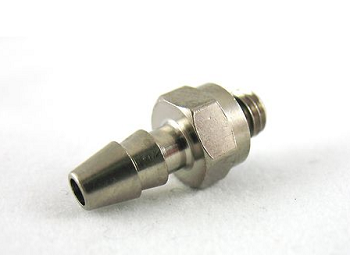
12x 10/32 barbed fittings. Order these with your solenoids, my distributor had them so hopefully any of them should. just pay for them along with the solenoids. they are cheap anyway. Here is a picture if you're confused
30 feet silicone vacuum hose 3mm ID 2x T-fittings (plastic works)
I'd go with black unless you like the look of hose everywhere, I'm gonna re-do mine. (note I used less than the 24ft I bought but it's nice to have extra)
Electrical wire, loom, heat shrink, solder and 8x .25" blade connectorsNot much, but if you don't already have a spool of black wire around your garage you clearly don't do enough wiring work. Loom is gonna be a bit less than 3ft
Small Diameter threaded rod and 4 nuts to thread on itYou'll see why if you look at the pictures
Step 3: BeginOk so you've got your solenoids right? good down first thing you're gonna want to do is label the ports. just like the factory solenoids there is an A, B, and C. When it doesn't have 12 volts applied air flows between B and C. When it does have 12 volts applied air flows between A and B. so make sure you have these labeled. once these are labeled then you are ready to get this project going. Basically there is a front top and back port. your front port is B, top port is C, and back port is A. I have those sleeves over the barbs because I ordered too small of barbs on accident and didn't have time to get more so I just made do.

Step 4:The Rack
Ok cool so now you have your solenoids and fittings. Take your threaded rod and turn it into an actual rack that looks something like this minus the extra fittings because of my experimentation. Also note, ignore the b written at the top of each solenoid that is wrong. refer to step 3 for this. Also at this point label which solenoid will be which. I believe my order from left to right was CC,CR,TC,PR.
Step 5:Wiring
Set your solenoids to the left of the ABS module, and hold the wires along the firewall to see about how far you need to extend them to reach under the manifold. make them too long if you have to, but not too short! Then put the blade connectors on the end of each. I would also group each pair of wires together and label which solenoid it goes to so you don't lose them and forget later!(no blade connectors in the image but you get the idea)
Step 6:Heat shield
Ok this is kind of optional. I did it for my project because of the requirements I set beforehand. After taking temp readings I found it's not really necessary but it does make it look a lot cleaner. Mine is now painted black, and with a black heat shield and hoses this would look very clean and probably not even be noticeable to most people. My heat shield also doubled as a mounting bracket so if you don't make something like this you'll have to find a different way to mount the solenoids. I'm just gonna put up some pics of how i made it.


Step 7:Install
Ok you ready for this? alright. Take your intake manifold off and toss it to the side. see those electrical connectors next to the ABS module? unclip them from the chassis and push them down out of the way, since this is where the solenoid rack is going. Now set the rack down and start feeding the wire loom along the firewall. Zip tie it in place and you should be left with what looks like just another piece of wiring harness along the firewall.

Ok cool you have a sweet looking solenoid rack that does nothing. Now, if you haven't done so already, disconnect and toss the old stock solenoids. say good riddance, burn them, stomp on them, stab them with a knife..whatever you please. Now don't forget which electrical connector goes to which solenoid because now you need to plug in the wiring. just take the two wires for each solenoid and attach them to the appropriate connector. it's just a 12V switched power so it doesn't matter + or - just plug them in. Mine were very secure, if yours is not a little electrical tape might be required. Sorry I don't have any great pictures of this but this is basically what you are looking for. and yes the orange hoses are as ugly as they look. I need to go get some black hose.
Now for the hoses. Here is the vacuum diagram you will be following. it is modified from the simplified sequential up at the top of this post.
Now as you can probably see the two t-fittings will be coming off of the charge control and charge relive solenoids. This helps minimize the number of hoses we have to run along the firewall. So attach the two t-fittings to begin with. Next I would start with the pressure control and turbo control. These each only have two lines coming off, the third is a dump port and can be left open, or you can put a snazzy little filter on it if you want. If anyone has input on why you absolutely should or should not let me know. Basically start with these because they are easy, you simply replace what was once there with longer hoses to the new solenoids. Just make sure you attach them to the proper ports and it's all smooth sailing.
Same goes for CC and CR though as you may have noticed, the hose system from the vacuum chamber still splits off in many places. This is where I decided to utilize the factory rats nest instead of having a billion T-fittings all over the place. it just makes it easier, and luckily there is one piece that has outputs for each of the four places it will need to attach. Basically you can utilize the rats nest however you want to accomplish your routing, just make sure that the two ports you think are connected are actually connected
it can get confusing in there I know.
Last edited by RedRevolver; Apr 15, 2012 at 09:26 PM.
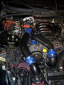
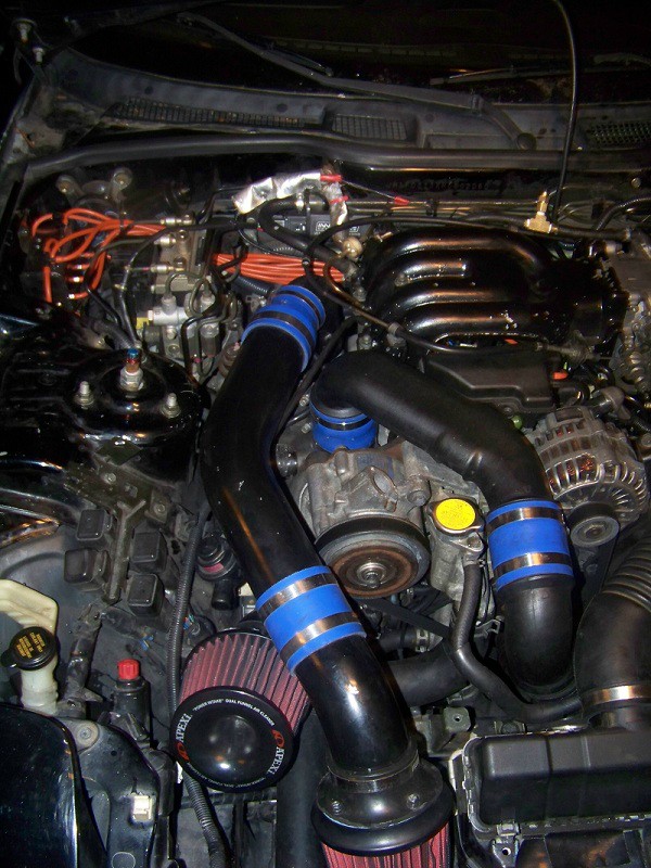
In the end you will be left with something like this. Be sure to use zip ties accordingly when you are done it helps a lot with how nice it all looks! (also helps if you have black hose.....yes, I am still kicking myself for it, and yes, I am too lazy to take the time to route new hoses) Also note again that because of the solenoids I have my setup is slightly different, as you can see I only have one tee fitting. But IMO it is simpler to order one type of solenoid and do it this way.
So the end result? it works. what more did you expect? well in my case the crossover 8psi dip has been virtually eliminated. added bonus I guess. cool. this is my first DIY ever so if you have any suggestions let me know.
So the end result? it works. what more did you expect? well in my case the crossover 8psi dip has been virtually eliminated. added bonus I guess. cool. this is my first DIY ever so if you have any suggestions let me know.


nice.
it may be beneficial for those who also want to do it themselves, is to give your approximate cost and supplier of solenoids. Not to play favorites to one supplier or another, but it will be a start for someone who just googles the part number and doesnt get far.
I've been working with peterpaul electronics for mine. the fabcos are apparently rebadged p.p.e. ones.
approx. $250 for a setup from peterpaul (fittings from mcmaster)
Last edited by nismosilvia270r; Apr 15, 2012 at 11:15 PM.

nice.
it may be beneficial for those who also want to do it themselves, is to give your approximate cost and supplier of solenoids. Not to play favorites to one supplier or another, but it will be a start for someone who just googles the part number and doesnt get far.
it may be beneficial for those who also want to do it themselves, is to give your approximate cost and supplier of solenoids. Not to play favorites to one supplier or another, but it will be a start for someone who just googles the part number and doesnt get far.
Last time in investigated these options in detail I determined that their are slight diffeences between the Fabco and PPE valve-solenoid sets; I believe each manufacture their own.
haha, looks like i missed that. in that case, a grand total for those of us that cant do math.
the salesman at ppe wasnt really interested in selling just four solenoids, and when i mentioned fabco, he said that fabco is his largest buyer and i should just buy the solenoids from them (with mark-up of course).
i think fabco makes different options for the bodies. ppe doesnt have the 4-way
i think fabco makes different options for the bodies. ppe doesnt have the 4-way
Trending Topics

Glad you made this work.
However the vacuum diagram was confusing and very hard to see (just my opinion). But I guess it is doable since you are not selling a kit or anything. Big props for making a DIY for the DIYers.
Also, what's that big fitting in between the 2 solenoids? Was it there to share vacuum? To me it just look very awkward and the solenoids can be re-arranged for better purposes. Yes you've eliminated some T fittings, but that fitting really is an eyesore LOL. Not trying to cap on your work but I seriously think re-positioning the solenoids would probably be a better idea dont you think?
Also, you might need to include the solenoid information for this project. Like a detail graph that shows which solenoids you are replacing so when people remove their UIM they can figure out which solenoid they need to remove (I.E. their location, color of their harness connectors and such). Then of course, the power and ground is straight forward.
I am here to give advice, not to shoot you down for your hardwork. Therefore if you do not like my advice, please disregard my info from above.
Anyways, thumbs up for getting it done.
-Eric
Last edited by AzEKnightz; Apr 16, 2012 at 02:12 AM.
thanks for the suggustions azeknightz. that honkin fitting is from the 103M solenoid I had to block one side off and thats what I had lol. hence also why this tutorial keeps it simple and just uses 4x 10³SM's instead. also another reason for a heat shield, doesn't have to look pretty underneath =P and the heat shield looks much much better now that its black as well.
I think if someone follows the directions top to bottom and labels the solenoids the diagram isn't too bad. it kind of goes to the first don't overthink it step. start with attaching your hose to the solenoid and then route it to it's destination. if you can do simplified sequential you can do this. if anyone gets into their project and gets confused by something I am more than happy to help just shoot a PM.
as far as unsightlyness of T-fittings, yeah i agree, but a little extra hose is all thats needed to get it tucked behind something, which is what I'll do when I re-do it with black hoses. I also just have a lot of ugly things in general that need to be cleaned up in my engine bay haha. but my motorcycle gets all my attention these days so she can wait lol.
Ok so I guess I can't edit my original post but electrical connectors I believe are this:
Orange=Pressure Regulator
Brown=Turbo Control
White=Charge Control
Black=Charge Relief
not 100% sure here off the top of my head so if someone could verify that would be great
Orange=Pressure Regulator
Brown=Turbo Control
White=Charge Control
Black=Charge Relief
not 100% sure here off the top of my head so if someone could verify that would be great
Ok so I guess I can't edit my original post but electrical connectors I believe are this:
Orange=Pressure Regulator this one shouldnt need to be modified
Brown=Turbo Control
White=Charge Control
Black=Charge Relief
not 100% sure here off the top of my head so if someone could verify that would be great
Orange=Pressure Regulator this one shouldnt need to be modified
Brown=Turbo Control
White=Charge Control
Black=Charge Relief
not 100% sure here off the top of my head so if someone could verify that would be great
there are usually two turbo control valves. the pressure regulator shouldnt have needed to be modified.
normally just use (E) , (F) , (H) , and the "Solenoid Valve (Turbo Control)"
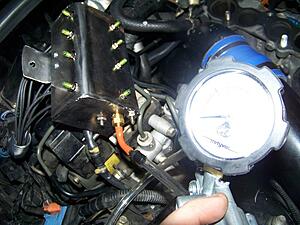
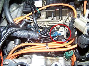
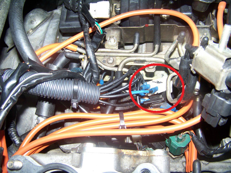
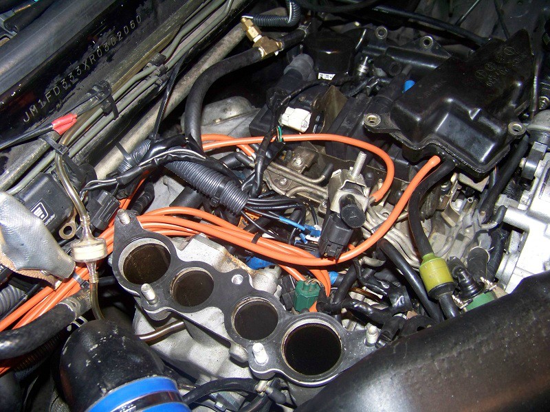
its the solenoid with small black connector thats pointing straight at the camera in this picture. the connector is different from the other three.

Last edited by nismosilvia270r; Apr 16, 2012 at 11:02 PM.
this isn't about replacing that turbo control valve, it's a two way solenoid. I did replace the pressure regulator on my setup. as you can see that is the stock turbo control valve with stock wiring going to it. later on when I have an aftermarket Fuel setup I will turn the current PR solenoid into that two way turbo control.
this isn't about replacing that turbo control valve, it's a two way solenoid. I did replace the pressure regulator on my setup. as you can see that is the stock turbo control valve with stock wiring going to it. later on when I have an aftermarket Fuel setup I will turn the current PR solenoid into that two way turbo control.
That vacuum solenoid is pretty unreliable, so most of the kits swap it out right away.
My post was more for readers that didn't know your future plans to switch it with Fpr. I didn't.
Last edited by nismosilvia270r; Apr 17, 2012 at 11:27 AM.


Sorry for reviving this thread...
Was planning on using the ebay Solenoid because Im having trouble getting a hold of the fabco ones. Think it'll be ok to use?
1 4" Electric Solenoid Valve 3 Way 12 V DC B30V | eBay
Was planning on using the ebay Solenoid because Im having trouble getting a hold of the fabco ones. Think it'll be ok to use?
1 4" Electric Solenoid Valve 3 Way 12 V DC B30V | eBay


Thread
Thread Starter
Forum
Replies
Last Post
joel(PA)
Group Buy & Product Dev. FD RX-7
8
Oct 4, 2015 06:07 PM
joel(PA)
Race Car Tech
0
Oct 1, 2015 10:25 AM