
Data interface with stock ECU


Thread Starter
Full Member
Joined: Jun 2009
Posts: 85
Likes: 1
From: Chch, New Zealand
Data interface with stock ECU
I've been working on an data link interface to the stock mazda ECU & have made pretty good progress, so I figured I'd post it here in case someone wants to make one for themselves.
A while ago I stumbled across a link to this site (which is a real information goldmine on the stock ECU):
http://www.kaele.com/~kashima/car/rx7.html
Which sadly is in Japanese. However, Google translate does a pretty good job, and I've been able to implement the communications interface that he reverse engineered.
For those that have seen the TechTom MDM-100Z (http://www.technosquareinc.com/mdm.htm), or heard about the 'DT-S1000' in the FSM - this is the same thing, just PC based.
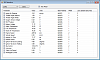
Here is a wee screenshot of the software that I've developed in the last few evenings - if you look closely you'll note the engine is off & car stationary.
The hardware is really simple, it took me perhaps 2-3 hours to solder it all together.
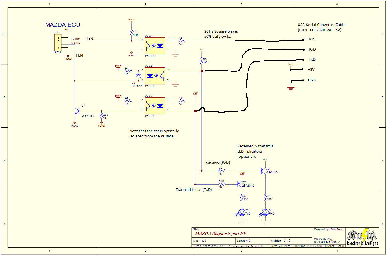
I've attached a simplified schematic of the one on Kashima's site - it was made simpler by using a pre-made USB-serial converter (which also is much more compact & works with modern netbooks that don't have serial ports).
I'm happy to help with anyone needing more details on making it.
Any of the transistors or opto-coupler parts can be replaced with any generic one. (I used 3x h11a817 optocouplers and BC337 & BC327 transistors).
I won't post the software here yet, as it's still in progress (and no one has the hardware), but for those that want an early peek at it or the source code, just give me a PM. I'll make it fully open source too, I see little point in attempting to make a commercial product based on a 20 year old ECU that is usually replaced asap
Just a few notes:
- The ECU is rather slow (its 8 bit!!!), and can only spit out upto 6 or so readings per second. For example, you could log 6 boost readings per second, or 3 boost & 3 rpm readings per second. The speed also varies depending on what the ECU is doing, sometimes it is just too busy & drops packets for half a second or so - I'm guessing it is pretty maxxed out in terms of CPU usage. The software could improve this by optimizing the packet interface (there is probably room for a 50-100% performance increase, so perhaps upto 10 readings per second will be possible).
- The series 7 & 8 ECU will also work, but has different addresses. I don't have one to test with, but I can copy the data posted on the Japanese site, and it should be correct.
Now I do realize that most people here have powerFC's, but for those that don't this is a pretty nifty tool, and with some more work the software could be turned into a nice digital dash.
A while ago I stumbled across a link to this site (which is a real information goldmine on the stock ECU):
http://www.kaele.com/~kashima/car/rx7.html
Which sadly is in Japanese. However, Google translate does a pretty good job, and I've been able to implement the communications interface that he reverse engineered.
For those that have seen the TechTom MDM-100Z (http://www.technosquareinc.com/mdm.htm), or heard about the 'DT-S1000' in the FSM - this is the same thing, just PC based.
Here is a wee screenshot of the software that I've developed in the last few evenings - if you look closely you'll note the engine is off & car stationary.

The hardware is really simple, it took me perhaps 2-3 hours to solder it all together.
I've attached a simplified schematic of the one on Kashima's site - it was made simpler by using a pre-made USB-serial converter (which also is much more compact & works with modern netbooks that don't have serial ports).
I'm happy to help with anyone needing more details on making it.
Any of the transistors or opto-coupler parts can be replaced with any generic one. (I used 3x h11a817 optocouplers and BC337 & BC327 transistors).
I won't post the software here yet, as it's still in progress (and no one has the hardware), but for those that want an early peek at it or the source code, just give me a PM. I'll make it fully open source too, I see little point in attempting to make a commercial product based on a 20 year old ECU that is usually replaced asap
Just a few notes:
- The ECU is rather slow (its 8 bit!!!), and can only spit out upto 6 or so readings per second. For example, you could log 6 boost readings per second, or 3 boost & 3 rpm readings per second. The speed also varies depending on what the ECU is doing, sometimes it is just too busy & drops packets for half a second or so - I'm guessing it is pretty maxxed out in terms of CPU usage. The software could improve this by optimizing the packet interface (there is probably room for a 50-100% performance increase, so perhaps upto 10 readings per second will be possible).
- The series 7 & 8 ECU will also work, but has different addresses. I don't have one to test with, but I can copy the data posted on the Japanese site, and it should be correct.
Now I do realize that most people here have powerFC's, but for those that don't this is a pretty nifty tool, and with some more work the software could be turned into a nice digital dash.
 (I still have the stock ecu just JDM)
too bad you could not make the honda ecu work for fd since they run so well and they have chrome and all the other interfaces that work with them. not to mention they have 4 spark plugs and 4 injectors all u need is a patch harness to plug into fd harnesses and software that can do split timing ect


VERY cool! I've wanted someone to figure out that interface for years.
This could be really useful for diagnosing problems and stuff.
As you get farther along, I'd love to see a list of components and maybe a quick how-to on making the cable. I'd be happy to help test build and document it. I'm not gifted on electronics, but I can solder and figure stuff out quite well .
.
Dale
This could be really useful for diagnosing problems and stuff.
As you get farther along, I'd love to see a list of components and maybe a quick how-to on making the cable. I'd be happy to help test build and document it. I'm not gifted on electronics, but I can solder and figure stuff out quite well
.Dale
Thread Starter
Full Member
Joined: Jun 2009
Posts: 85
Likes: 1
From: Chch, New Zealand
The usb-serial cable itself is a $17 part that can be bought from various places, such as http://www.sparkfun.com/commerce/pro...oducts_id=9718 (Sparkfun is a really good shop for electronic parts, great prices too).
The rest of the parts would cost less than $4, plus the prototyping board (another $4 or so). So cheap as chips really!
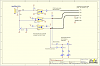
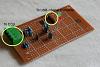
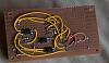
Here are a few pics of the hardware board itself - My version is a bit more complex than it needs to be (I could only get hold of a 3.3V usb-serial cable, so had to add a 3.3V regulator in order to make the LEDs work). Ultimately the LEDs could be skipped altogether as they aren't really useful.
I'm happy to make up a component list - I just need to know where you guys typically get your electronic components from in the USA?
I have a JDM rx7 myself, ECU code N3A8. I haven't tested this with the N3A1 ECU's (we don't get those over here in NZ), but I see no reason why it wouldn't work as they are virtually identical (plus the TechTom unit works with both US & JDM ecus).
Thanks for the credit, but 99% of the work was done in 2000 by the guy at http://www.kaele.com/~kashima/car/rx7.html Without him publishing the protocol, this would not be possible.
The rest of the parts would cost less than $4, plus the prototyping board (another $4 or so). So cheap as chips really!
Here are a few pics of the hardware board itself - My version is a bit more complex than it needs to be (I could only get hold of a 3.3V usb-serial cable, so had to add a 3.3V regulator in order to make the LEDs work). Ultimately the LEDs could be skipped altogether as they aren't really useful.


I'm happy to make up a component list - I just need to know where you guys typically get your electronic components from in the USA?
Wow, that's cool, keep up the good work. I am quite interested in this project of yours (I still have the stock ecu just JDM).
Thanks for the credit, but 99% of the work was done in 2000 by the guy at http://www.kaele.com/~kashima/car/rx7.html Without him publishing the protocol, this would not be possible.

Joined: Mar 2001
Posts: 31,851
Likes: 3,239
From: https://www2.mazda.com/en/100th/
^ +1 Digikey is where i get my odds and ends, if you want any help testing wise I can build a board and see what I get, I am like Dale in the sense that I know just enough to be dangerous lol
Keep us posted
Mike
Keep us posted
Mike
Trending Topics
Thread Starter
Full Member
Joined: Jun 2009
Posts: 85
Likes: 1
From: Chch, New Zealand
Ok, just had a look on Digikey, and came up with the following list:
USB->Serial Converter Cable:
http://search.digikey.com/scripts/Dk...me=768-1028-ND
Pin header (for mating with the usb-serial cable connector):
http://search.digikey.com/scripts/Dk...&name=A1923-ND
(or any sort of pin header strip will do).
1x Optocoupler (4 channel):
http://search.digikey.com/scripts/Dk...=160-1370-5-ND
1x Transistor NPN BC337:
http://search.digikey.com/scripts/Dk...&name=BC337-ND
1x Diode:
http://search.digikey.com/scripts/Dk...me=1N4148FS-ND
5x Resistor 1K ohm:
http://search.digikey.com/scripts/Dk...ame=1.0KQBK-ND
5x Resistor 330 ohm:
http://search.digikey.com/scripts/Dk...name=330QBK-ND
5x Resistor 10K ohm:
http://search.digikey.com/scripts/Dk...name=10KQBK-ND
Prototype Board (small or large - it'll fit on a 2x3" board, but depends how well you think it through):
http://search.digikey.com/scripts/Dk...&name=V2025-ND
http://search.digikey.com/scripts/Dk...&name=V2010-ND
For the optional LED Indicators:
2x Transistor PNP BC327:
http://search.digikey.com/scripts/Dk...&name=BC327-ND
LEDs (Get 1 of each color):
http://search.digikey.com/scripts/Dk...me=754-1211-ND
http://search.digikey.com/scripts/Dk...me=754-1210-ND
I haven't listed the connectors for the board-ECU interface, as finding connectors on online catalogs is a real pain. Just go to your local shop and grab a nice screw terminal plug & socket.
I suggest you order 1 of the serial cables & 1 board, and get 2x of everything else. But it all depends how good you at soldering you are! - it's pretty straightforward, but given that everything is so cheap, its more annoying having to make another order because you stuffed up soldering a transistor.
Thats everything (apart from the wire & solder etc, but I assume you all have that!).
about the sample rate... 6 samples per second (total) is not surprising or unusual. The mandated universal OBD II protocol only has 5 samples per second. Manufacturers may have a separate interface that is faster.
Thread Starter
Full Member
Joined: Jun 2009
Posts: 85
Likes: 1
From: Chch, New Zealand
Mazdas interface (would be very interested to see if other pre-OBDII mazdas have the same interface) is approximately 100 bytes per second. Their protocol allows you to get it to spit data out as fast as it can (as opposed to the request-response method I'm using atm) - which I haven't tried yet, but I suspect it may get upto 25 samples per second or so for a single reading type.
One of the other projects listed on that japanese site are about communicating directly to the ECU processor & is able to read well over 10K samples per second. However that one requires opening up & modifying the ECU & I really can't be bothered going that far.
As for the software, did a bit more work & have been working on a digital dash type setup. Works nicely on my desktop PC, but is a bit laggy on the netbook in the car. The drawing routines aren't suited to low-power laptop processors, so I'll need to work on that a bit.
I've been trying to find the other data readings that should be possible (from the list the TechTom can read):
CRFSV Charge Relief Valve ON . OFF
CCNTSV Charge Control Valve ON . OFF
RAD-FAN1 Radiator Fan Relay 1 ON . OFF
RAD-FAN2 Radiator Fan Relay 2 ON . OFF
RAD-FAN3 Radiator Fan Relay 3 ON . OFF
AC-SW AC Switch ON . OFF
AC-RLY AC Relay ON . OFF
PRCSV Pressure Regulator Control Valve ON . OFF
DTCNTSV Double Throttle Control Valve ON . OFF
FP-RLY Fuel Pump Relay ON . OFF
Diagnostic Code OK.NG CODE
I've found 2 addresses that have non-zero data that changes, but haven't been able to figure out what they are. They ones I would like to find are the soleniod control ones, I'm not too concerned about AC or radiator fans at the moment.

Thread Starter
Full Member
Joined: Jun 2009
Posts: 85
Likes: 1
From: Chch, New Zealand
I'll post up a link to the software when I get home from work.
It's written in C#, and requires .net framework 2.0. Windows XP and newer typically already have it installed, but otherwise it's just a 22MB download.
Thread Starter
Full Member
Joined: Jun 2009
Posts: 85
Likes: 1
From: Chch, New Zealand
Here's the software. Luckily .Net applications are really small, so I can attach it - the zip with the .exe and source is only 60KB, but if this gets too large I'll stick it on my website or something.
Have a read of the readme.txt if you need help using it. But I suspect no ones got their hardware fully finished yet
Have a read of the readme.txt if you need help using it. But I suspect no ones got their hardware fully finished yet


DUDE!!!! AWESOME!!!!!!!!!!!!!! I still have the stock ECU and I am loosing my mind trying to figure out some of the issues I have after my rebuild with mods. I definitely need this!
Once again, AWESOME!!!! Gonna build this ASAP!!!
Once again, AWESOME!!!! Gonna build this ASAP!!!
Thread Starter
Full Member
Joined: Jun 2009
Posts: 85
Likes: 1
From: Chch, New Zealand
I haven't been able to do any work on it in the past few weeks - had to track down a ruptured coolant hose & replace it (it was the one going out of the block to the TB). Then it's been raining all weekends so I haven't been able to drive & find some of these missing values. The list arghx posted suggests there are alot more hidden in there, but finding them will be a slow process. Don't hold high hopes for it, not unless I get lucky.
If anyone has built one up & plugged it in, I'd be interested to know how you get on.
If anyone has built one up & plugged it in, I'd be interested to know how you get on.
Some other interesting threads on similar topics about the stock ecu from HWND
https://www.rx7club.com/3rd-generation-specific-1993-2002-16/stock-mazda-fuel-ignition-maps-876250/
https://www.rx7club.com/3rd-generation-specific-1993-2002-16/motorola-developers-875273/
https://www.rx7club.com/3rd-generation-specific-1993-2002-16/stock-mazda-fuel-ignition-maps-876250/
https://www.rx7club.com/3rd-generation-specific-1993-2002-16/motorola-developers-875273/
OK, Just purchased enough components to build two units. I hope this works cause I'm on my last straw with this car. Thouse of you that have built this, how is it working for you? Is it as simple as it seems?
Thread Starter
Full Member
Joined: Jun 2009
Posts: 85
Likes: 1
From: Chch, New Zealand
Either no one has built it yet (I'm guessing most are using PFC nowadays), or its so simple they aren't posting any questions 
Before you start soldering, get all the datasheets (for the optosisolator and the transistors) open or print em out. That way you can double and triple check you are soldering to the correct pin. I'd suggest not putting the LED's on to start with, they aren't needed at all.
For me, the hardest part was getting a decent connection to the car's harness - I inserted little pins into the back of the ECU plugs, but getting them to stay & have a decent contact was a pain. For the first time (ie testing it), just wire it into the DIAGNOSIS port under the bonnet, much, much easier.
yea, I was thinking the same thing about the LEDs. i am definitely gonna use them but to make sure it works, i'll add them later. BTW, Thanks for responding. I know most may have a PFC but my pockets cant handle that just yet. Got another project car i'm building at the same time so I have to be conserative with my dough. besides, the stock ecu can handle quite a bit of upgrades as long as 10 psi boost is kept and thats fine with me! I'll still be the fastest in my area.
ok guys, Interface is built and just about ready to give this thing a shot. Any last tips? Does the car have to have any other jumpers to give me the ecu info or is it just the four pins (TEN,FEN, B+, and the Ground)?