
Code 27, all obvious things checked

Thread Starter
Exhaust Manifold Leak

Joined: Jun 2005
Posts: 815
Likes: 42
From: western europe
Code 27, all obvious things checked
Hi,
I have here a 93 jspec fd. Stock apart from a tuned ecu. Car worked fine for the last years but now it gives a code 27, omp sensing circuit.
I replaced the OMP with a known good S5 one because the old one had some water when a water hose failed at the back of the waterpump housing, I re-pinned the OMP harness so it has an FD connector. All back together car does same. As soon as its warm it limps and gives one code, 27...
I checked the harness, its good. Checked the resistances of the OMP as per manual, theyre good. Tested 2 other known good ecus. No change. The 5v and ground are good at the pos sensor.
When the engine is cold and u give some throttle the feedback voltage of the OMP varies between 4 and 3v approx. When warm it stays at 4v
As per my understanding the 4v represents full flow as manual states at idle one should see around 1v. Im a bit puzzled now as what could cause this. When cold car drives and boosts as it should.
Last edited by Rub20B; Sep 17, 2017 at 03:39 PM.


Did you follow the service procedure first, and then come to the conclusion that the OMP had failed because its voltage or resistance were out of spec? Or did you see an OMP code, grab a part for a completely different vehicle because you were unwilling to get the correct the part, install it, wonder why it wasn't working, and then follow the service procedure and be confused why installing the wrong part didn't fix the problem?
Undo your S5 OMP swap. Buy a new S6 OMP and install it. Or put in the original OMP again and re run the diagnostic procedure. Or get an aftermarket ECU and go premix only. Or roll the dice on a used S6 OMP.
S5 engine has a different oil metering system with 4 nozzles and a different rotor housings surface with higher friction. It doesn't belong in an FD. It's scheduled based on airflow based OMP maps according to what Mazda has published. The FD doesn't even have an airflow meter. Running an OMP designed for an airflow meter based control system on an engine that doesn't have an airflow meter defeats the purpose of keeping an OMP, namely factory engineered oiling.
Thread Starter
Exhaust Manifold Leak
Joined: Jun 2005
Posts: 815
Likes: 42
From: western europe
Did you follow the service procedure first, and then come to the conclusion that the OMP had failed because its voltage or resistance were out of spec? Or did you see an OMP code, grab a part for a completely different vehicle because you were unwilling to get the correct the part, install it, wonder why it wasn't working, and then follow the service procedure and be confused why installing the wrong part didn't fix the problem?
Undo your S5 OMP swap. Buy a new S6 OMP and install it. Or put in the original OMP again and re run the diagnostic procedure. Or get an aftermarket ECU and go premix only. Or roll the dice on a used S6 OMP.
S5 engine has a different oil metering system with 4 nozzles and a different rotor housings surface with higher friction. It doesn't belong in an FD. It's scheduled based on airflow based OMP maps according to what Mazda has published. The FD doesn't even have an airflow meter. Running an OMP designed for an airflow meter based control system on an engine that doesn't have an airflow meter defeats the purpose of keeping an OMP, namely factory engineered oiling.
Undo your S5 OMP swap. Buy a new S6 OMP and install it. Or put in the original OMP again and re run the diagnostic procedure. Or get an aftermarket ECU and go premix only. Or roll the dice on a used S6 OMP.
S5 engine has a different oil metering system with 4 nozzles and a different rotor housings surface with higher friction. It doesn't belong in an FD. It's scheduled based on airflow based OMP maps according to what Mazda has published. The FD doesn't even have an airflow meter. Running an OMP designed for an airflow meter based control system on an engine that doesn't have an airflow meter defeats the purpose of keeping an OMP, namely factory engineered oiling.
I did follow the procedure and found the S6 stepper motor to be bad. it has one winding with very high resistance, possibly
the S5 stepper has all windings good, wire color is also same as is the resistance and length of the pos sensor. so I cannot understand why an S5 stepper and pos sensor would not be interchangable with S6 item besides the connector and wire length.
Last edited by Rub20B; Sep 18, 2017 at 02:47 AM.
Agree with arghx. Frankensteining an OMP makes no sense. Except that buying a NEW OMP probably isn't practical...they're silly expensive. IIRC over $1000 U.S. Still, there should be many good used ones available, just deal with someone with a good track record.
Thread Starter
Exhaust Manifold Leak
Joined: Jun 2005
Posts: 815
Likes: 42
From: western europe
unless someone has a proof there would be some difference between them which I overlooked.
So, we know that the OMP as a pump is physically different between series 5 and series 6.
The series 6 service highlights briefly outlines the two major differences:

The series 6 uses 2 oil injectors (center of rotor housing only) and a low friction rotor housing rather than 4 oil injectors like the series 5, which drips oil into the actual air stream as well as putting it directly on the rotor housing. The actual discharge rate vs OMP valve position relationship is different as well.
Now let's discuss how the on board diagnostic and failsafe mode (limp mode) works for a series 5 FC and series 6 Rx-7. It's pretty advanced for its time.
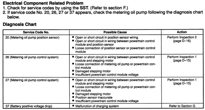
So we've got 3 codes.
Code 20 and Code 26 are dumb "OBD 1" style codes. They basically detect an open circuit (something disconnected) or a short circuit (a positive/hot wire touching metal). Code 20 is for the position sensor and Code 26 is for the stepper motor.
Now, look closely at code 26 and code 27. What's the difference between the two? "Position Sensor Inaccurate" is in code 27. That's what's called a rationality monitor. It goes beyond just knowing whether the thing is plugged in or not or if the insulation has melted. It's OBD II level sophistication in a car that was designed in the 80s.
Rationality Monitors - Modern Examples
Here's a comparison with a modern car. If you unplug the o2 sensor in a modern car, it will throw a code. You can't just pop a resistor in there though and keep driving. It will figure out that it's being fooled. The ECU compares the measured value to an expected value to see if what the sensor is reporting is making sense. That's how a rationality monitor works.
Here's another example. On an OBD II engine that has a mass airflow sensor and no MAP sensor, the ECU can diagnose a bad mass airflow sensor by looking at a modeled manifold pressure based on the mass airflow sensor and a modeled manifold pressure based on the throttle position. If the MAF based calculation is outside an acceptable range, we can trigger an error code, and the engine will go into some sort of failsafe condition. That's a mass airflow sensor rationality monitor.
Active vs Passive Diagnostic Monitors
Now there are two main types of diagnostic monitors: passive monitors and active/intrusive monitors. Typically they are not activated until certain criteria are met, such as coolant temperature. Usually the OEM will try to run the monitor as little as it can get away with so as to not impact the customer, and CARB will try to push the OEM to run it more so that they can detect an emissions problem. If CARB gets mad enough they will fine the OEM and force a recall to make the diagnostic monitor run more.
Passive monitors are running in the background comparing the current value to the expected value. They don't interfere with engine operation. What I roughly described above for the mass airflow sensor monitor is basically a passive monitor. The throttle position sensor (especially on an electronic throttle equipped engine like the Rx-8 has) is considered the dependable signal and if the mass airflow signal is off then it means that sensor is bad, or so the logic goes.
Active monitors directly interfere with engine operation to make sure a component is working right. They can also be called "intrusive monitors." In the case of an OBD II car, it might force the engine into a specific target air fuel ratio pattern and then confirm that the O2 sensor is reading as expected. That can have an impact on emissions so they are used more sparingly. On an oil metering pump the ECU might force the pump to step open and closed and confirm the sensor is reading as expected, but that could cause additional oil consumption, so it might only run once in a while, like when the battery has been disconnected and the learning values reset.
So with a rationality monitor you are storing some learning value in the ECU to make that comparison between expected and actual. Keep in mind that on old ECU's there were especially limited resources for doing extra computations and storing memory values. Since the oil metering pump is a critical engine component Mazda decided to devote memory and processing to it. The service manual actual instructs the technician to unplug the battery because there are stored diagnostic values.
If the component is judged to have failed by either of those methods, the engine goes into a failsafe mode. Below notice that code 27 talks about a "sticking" sensor, meaning that the ECU is smarter than just throwing a code when the thing is unplugged.
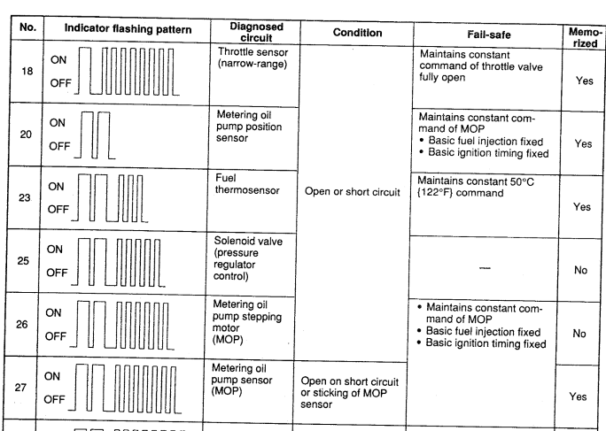
Now think about the failsafe condition. Since the oil metering pump still dribbles a little oil even when the electrical system fails, the engine can run but is torque limited to keep the apex seal temperatures within acceptable range. That's why it says "basic fuel injection fixed" and "basic ignition timing fixed." It's limiting engine torque. Only the stock ECU is smart enough to have a rationality monitor and a failsafe system for a bad OMP.
So how does this relate to the OP's situation? I don't know the exact diagnostic algorithm in the stock ECU, but we can infer what it is looking at. It must have some expected resistances as a passive monitor and maybe it has an active monitor as well I do know that the service specifications between the series 5 and series 6 are NOT the same. And the ECU is smart enough to tell the difference. Let's compare "Inspection 1" and "Inspection 2" for both the Series 6 FD and the Series 5 FC. The two pumps have different connectors but the basic terminals are the same, with a slight change in the nomenclature.
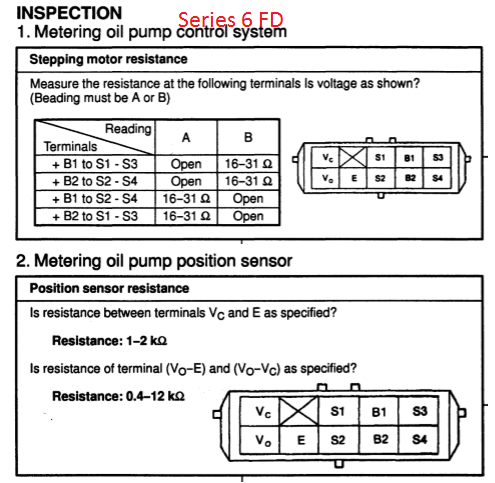
Inspection 1 is for the motor, Inspection 2 is for the position sensor. Here it is for the series 5 FC:
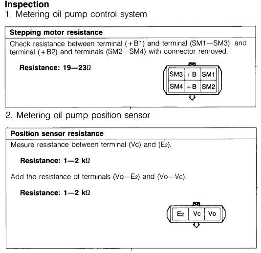
The stepper motor isn't too far off, but the resistance sweep of the series 5 position sensor vs series 6 is way different. This is likely the cause of it failing the rationality check and causing code 27.
Now, that doesn't mean that I'm 100% positive I'm right. I don't have the car in front of me, something could be up with the harness, all sorts of other stuff could be going wrong. But it behooves the OP to swap in a known good FD OMP, or at least the electrical portion.
The series 6 service highlights briefly outlines the two major differences:
The series 6 uses 2 oil injectors (center of rotor housing only) and a low friction rotor housing rather than 4 oil injectors like the series 5, which drips oil into the actual air stream as well as putting it directly on the rotor housing. The actual discharge rate vs OMP valve position relationship is different as well.
Now let's discuss how the on board diagnostic and failsafe mode (limp mode) works for a series 5 FC and series 6 Rx-7. It's pretty advanced for its time.
So we've got 3 codes.
Code 20 and Code 26 are dumb "OBD 1" style codes. They basically detect an open circuit (something disconnected) or a short circuit (a positive/hot wire touching metal). Code 20 is for the position sensor and Code 26 is for the stepper motor.
Now, look closely at code 26 and code 27. What's the difference between the two? "Position Sensor Inaccurate" is in code 27. That's what's called a rationality monitor. It goes beyond just knowing whether the thing is plugged in or not or if the insulation has melted. It's OBD II level sophistication in a car that was designed in the 80s.
Rationality Monitors - Modern Examples
Here's a comparison with a modern car. If you unplug the o2 sensor in a modern car, it will throw a code. You can't just pop a resistor in there though and keep driving. It will figure out that it's being fooled. The ECU compares the measured value to an expected value to see if what the sensor is reporting is making sense. That's how a rationality monitor works.
Here's another example. On an OBD II engine that has a mass airflow sensor and no MAP sensor, the ECU can diagnose a bad mass airflow sensor by looking at a modeled manifold pressure based on the mass airflow sensor and a modeled manifold pressure based on the throttle position. If the MAF based calculation is outside an acceptable range, we can trigger an error code, and the engine will go into some sort of failsafe condition. That's a mass airflow sensor rationality monitor.
Active vs Passive Diagnostic Monitors
Now there are two main types of diagnostic monitors: passive monitors and active/intrusive monitors. Typically they are not activated until certain criteria are met, such as coolant temperature. Usually the OEM will try to run the monitor as little as it can get away with so as to not impact the customer, and CARB will try to push the OEM to run it more so that they can detect an emissions problem. If CARB gets mad enough they will fine the OEM and force a recall to make the diagnostic monitor run more.
Passive monitors are running in the background comparing the current value to the expected value. They don't interfere with engine operation. What I roughly described above for the mass airflow sensor monitor is basically a passive monitor. The throttle position sensor (especially on an electronic throttle equipped engine like the Rx-8 has) is considered the dependable signal and if the mass airflow signal is off then it means that sensor is bad, or so the logic goes.
Active monitors directly interfere with engine operation to make sure a component is working right. They can also be called "intrusive monitors." In the case of an OBD II car, it might force the engine into a specific target air fuel ratio pattern and then confirm that the O2 sensor is reading as expected. That can have an impact on emissions so they are used more sparingly. On an oil metering pump the ECU might force the pump to step open and closed and confirm the sensor is reading as expected, but that could cause additional oil consumption, so it might only run once in a while, like when the battery has been disconnected and the learning values reset.
So with a rationality monitor you are storing some learning value in the ECU to make that comparison between expected and actual. Keep in mind that on old ECU's there were especially limited resources for doing extra computations and storing memory values. Since the oil metering pump is a critical engine component Mazda decided to devote memory and processing to it. The service manual actual instructs the technician to unplug the battery because there are stored diagnostic values.
If the component is judged to have failed by either of those methods, the engine goes into a failsafe mode. Below notice that code 27 talks about a "sticking" sensor, meaning that the ECU is smarter than just throwing a code when the thing is unplugged.
Now think about the failsafe condition. Since the oil metering pump still dribbles a little oil even when the electrical system fails, the engine can run but is torque limited to keep the apex seal temperatures within acceptable range. That's why it says "basic fuel injection fixed" and "basic ignition timing fixed." It's limiting engine torque. Only the stock ECU is smart enough to have a rationality monitor and a failsafe system for a bad OMP.
So how does this relate to the OP's situation? I don't know the exact diagnostic algorithm in the stock ECU, but we can infer what it is looking at. It must have some expected resistances as a passive monitor and maybe it has an active monitor as well I do know that the service specifications between the series 5 and series 6 are NOT the same. And the ECU is smart enough to tell the difference. Let's compare "Inspection 1" and "Inspection 2" for both the Series 6 FD and the Series 5 FC. The two pumps have different connectors but the basic terminals are the same, with a slight change in the nomenclature.
Inspection 1 is for the motor, Inspection 2 is for the position sensor. Here it is for the series 5 FC:
The stepper motor isn't too far off, but the resistance sweep of the series 5 position sensor vs series 6 is way different. This is likely the cause of it failing the rationality check and causing code 27.
Now, that doesn't mean that I'm 100% positive I'm right. I don't have the car in front of me, something could be up with the harness, all sorts of other stuff could be going wrong. But it behooves the OP to swap in a known good FD OMP, or at least the electrical portion.
Trending Topics

Joined: Mar 2001
Posts: 31,849
Likes: 3,238
From: https://www2.mazda.com/en/100th/
interesting. i do recall that the position sensors were the same between the S5 and the FD, so if they read differently, they must have a different mechanical starting position.
my setup is an FD metering pump, FD ecu, but since i have an FC wiring harness, i used the FC position sensor, and probably the stepper too (maybe not, maybe it plugs in?)
my setup is an FD metering pump, FD ecu, but since i have an FC wiring harness, i used the FC position sensor, and probably the stepper too (maybe not, maybe it plugs in?)
It's also possible that OP is right and the sensor and stepper motor are swappable but there is something physically stuck inside the OMP. The ECU is running an intrusive monitor and commanding the OMP, but it is not responding as expected. Therefore it throws code 27 but not the other two because otherwise doesn't have an open circuit or short anywhere.
Thread Starter
Exhaust Manifold Leak
Joined: Jun 2005
Posts: 815
Likes: 42
From: western europe
It's also possible that OP is right and the sensor and stepper motor are swappable but there is something physically stuck inside the OMP. The ECU is running an intrusive monitor and commanding the OMP, but it is not responding as expected. Therefore it throws code 27 but not the other two because otherwise doesn't have an open circuit or short anywhere.
Botht he S5 and S6 specify warm idle the voltage should be around 1-1.2v. in this FD I see 4v (maximum oil flow postion). this was both the case with the original OMP electrical parts and now also with the swapped S5 hardware. When I changed the parts I obviously checked if the OMP register shaft wasnt mechanically stuck. It was moving freely, and had about the same resistance to sliding as the S5 OMP where I took the electrical componets from.
What does catch the eye is that with a cold engine, when ones revs up. voltage moves from 4v at idle to approx 3v when revving. With warm engine it stays at 4v no matter what (assumeable because the fault has been set and as a safety feature it drives the OMP to max flow).
it appears thus that the OMP works in the wrong direction. I have been thnking to swap the Vc and E pins on the pos sensor, but I pinned it as it was on the FD. colour wise. therefore either the color changed (unlikely) or someone messed with the car before and pinned the plug wrongly.
Is this a project or a repair? If its a repair, install the correct part and be done with it. If its a project you can keep trying to swap pins around, swap out electrical parts, guess how the ECU control logic works etc.

New to the Club!
Joined: Mar 2023
Posts: 1
Likes: 0
From: Puerto Rico
Hi , Did you find the solution to fixed?
Hi,
I have here a 93 jspec fd. Stock apart from a tuned ecu. Car worked fine for the last years but now it gives a code 27, omp sensing circuit.
I replaced the OMP with a known good S5 one because the old one had some water when a water hose failed at the back of the waterpump housing, I re-pinned the OMP harness so it has an FD connector. All back together car does same. As soon as its warm it limps and gives one code, 27...
I checked the harness, its good. Checked the resistances of the OMP as per manual, theyre good. Tested 2 other known good ecus. No change. The 5v and ground are good at the pos sensor.
When the engine is cold and u give some throttle the feedback voltage of the OMP varies between 4 and 3v approx. When warm it stays at 4v
As per my understanding the 4v represents full flow as manual states at idle one should see around 1v. Im a bit puzzled now as what could cause this. When cold car drives and boosts as it should.
I have here a 93 jspec fd. Stock apart from a tuned ecu. Car worked fine for the last years but now it gives a code 27, omp sensing circuit.
I replaced the OMP with a known good S5 one because the old one had some water when a water hose failed at the back of the waterpump housing, I re-pinned the OMP harness so it has an FD connector. All back together car does same. As soon as its warm it limps and gives one code, 27...
I checked the harness, its good. Checked the resistances of the OMP as per manual, theyre good. Tested 2 other known good ecus. No change. The 5v and ground are good at the pos sensor.
When the engine is cold and u give some throttle the feedback voltage of the OMP varies between 4 and 3v approx. When warm it stays at 4v
As per my understanding the 4v represents full flow as manual states at idle one should see around 1v. Im a bit puzzled now as what could cause this. When cold car drives and boosts as it should.
Hi , I have the same problem , I replace the omp but still have the same problem, when engine is cold car runs fine and boost as normal , drive the car and about 15 minutes and then acceleration fail . Please let me know if you fix the issue Thanks a lot