
Auto to Manual Harness Conversion


Thread Starter
Senior Member
Joined: Mar 2001
Posts: 524
Likes: 2
From: Roaring Spring, PA USA
Auto to Manual Harness Conversion
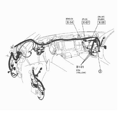
I need some help. I have installed a Manual Engine/Tranny assembly in my Auto car. I used the Manual harness and the X-05 and X-14 Connectors are not interchangeable (of course). I have researched the electrical schematics and have come up with the following final conversion.
I need help from everyone to proofread to correct any mistakes. I am utilizing all wires from the manual harness and have them routed to the correct pins to the ECU and Dash harnesses. I don't want to screw up and my brain hurts from tracing the wiring schematics.
There are two small harness connectors from the EM engine harness to the D dash harness that are identical to the EM harness (basically an extension of the harness). I took the connectors from the auto harness and carefully removed the pins from the manual harness. I reconfigured the manual wires into the Auto plug so it is now a "plug and play" as much as possible without having to cut and splice many wires.
Please review and post your comments. Thanks in advance.
Tim McCreary
Looking at the blue X-05 connector, I will describe it as the following:
Manual wires in Auto wires in
1 2 ----- 3 4 ............ A B C D E F------- G H I J K
5 6 7 8 9 10 .............L M N AA BB CC DD EE O P
Hopefully this above lines up properly visually. 1-10 are manual wires and the Auto wires are: A-P small pins, AA-EE large pins. The view is the EM harness from the engine to the dash (looking at the wires entering into the plug). I have taken the manual harness 10 wires and connected to this harness the following way:
COLOR - DESCRIPTION - POSITION IN X-05 AUTO CONNECTOR
Black/Green - magnetic clutch a/p ---- AA
Yellow - 1st gear switch ----------- N Connects to 2K at ECU
Brown/Black - Pressure sensor --------- P
Black/Blue - a/p magnetic clutch ------- K
Brown/White - Pressure Sensor --------- I
Black/Yellow - Injectors --------------------- BB
White/Blue - Cooling Relays -------------- J
Black/White - Solenoid Valves ----------- DD
Red - 2nd gear switch ----------------------- B Connects to 2L at ECU
Black from X-14 wire to X-05 ---------------H
Add Clutch Switch:
1 side to ground, other side connect to G
Add Clutch Interlock:
One side to CC one side to EE - Depressed ON allows starter to work with clutch in only.
Brown from X-05 - Neutral Switch - connect to Yellow at B1-01 EC/AT computer connnection. Connects to 1R at ECU
All other connectors left open with no wire connections.
Also, the X-14 EM connector 1-14 is the pin position of the manual, the A-R is the pins of the Auto EM harness (looking at the wires going into the back of the connector)
Manual wires In Auto Plug Wires In
1 2 3 ---------- 4 5 6 ...............A B C D ---- E F G H
7 8 9 10 11 12 13 14 ...............I J K L M N O P Q R
1 - Orange ------------------------------- I .. Speedo Input
2 - Yellow/Red ------------------------- J .. Rev Light Power to light
3 - Lt Green ---------------------------- Ground .. Neutral
4 - Yellow/White ---------------------- F.. Temp Gauge
5 - Brown/Yellow --------------------- G .. Fuel Thermo Sensor
6-------not used------
7 - Black - Over to X-05 Position H .. Cluster Ground
8 - Green -------------------------------- A .. Speedo Input
9 - Green/Yellow ---------------------- E .. Rev Light Power to Switch
10 - Blue --------------------------------- Ground .. 2nd Gear
11 - White ------------------------------- Ground .. 1st Gear
12 - Black/Yellow (Black/Red?) - P.. H2O thermo fan switch
13 - Blue/Green ----------------------- Q .. Neutral
14 - Yellow ------------------------------ R .. Elect Load input Signal.
I am just trying to verify that what I have done is correct and works without bypassing any of the original functions.
I believe that the cruise control will work as wired, but if not, there is an input wire from cruise computer that connects to the G position of the Blue X-05 connector if it does not work.
I just want to have someone confirm this before starting up the car. Any thing that you might have done that I missed or is wrong?
Thanks,
Tim McCreary


Full Member
Joined: Nov 2001
Posts: 98
Likes: 0
From: cincinnati
i can't confirm or deny but...i went thru all this when i did my tranny swap. just want to say if you did the rest, getting the cruise to work is a breeeze. just check the trouble shooting schematic and go pin by pin at the cruise ecu. you'll have a couple pins that need to be powered-up and your brakes won't kick out the cruise(no switch). no sweat, just drive and enjoy.
Thread Starter
Senior Member
Joined: Mar 2001
Posts: 524
Likes: 2
From: Roaring Spring, PA USA
Originally Posted by eurautodave
i can't confirm or deny but...i went thru all this when i did my tranny swap. just want to say if you did the rest, getting the cruise to work is a breeeze. just check the trouble shooting schematic and go pin by pin at the cruise ecu. you'll have a couple pins that need to be powered-up and your brakes won't kick out the cruise(no switch). no sweat, just drive and enjoy.
Tim
Trending Topics
magnetic clutch
Originally Posted by Mestre
Where is the b101 connector for the automatic transmission? I can't find that anywhere so it's currently not connected to anything. Would my car start without that plugged into anything?
what re the magnetic clutch wires for(black/blue and black/green)? and are they needed?
Last edited by imluvinit; Sep 4, 2005 at 03:27 AM.
Senior Member
Joined: Feb 2006
Posts: 436
Likes: 1
From: Oklahoma city, Oklahoma
Originally Posted by Tim McCreary
I need some help. I have installed a Manual Engine/Tranny assembly in my Auto car. I used the Manual harness and the X-05 and X-14 Connectors are not interchangeable (of course). I have researched the electrical schematics and have come up with the following final conversion.
I need help from everyone to proofread to correct any mistakes. I am utilizing all wires from the manual harness and have them routed to the correct pins to the ECU and Dash harnesses. I don't want to screw up and my brain hurts from tracing the wiring schematics.
There are two small harness connectors from the EM engine harness to the D dash harness that are identical to the EM harness (basically an extension of the harness). I took the connectors from the auto harness and carefully removed the pins from the manual harness. I reconfigured the manual wires into the Auto plug so it is now a "plug and play" as much as possible without having to cut and splice many wires.
Please review and post your comments. Thanks in advance.
Tim McCreary
Looking at the blue X-05 connector, I will describe it as the following:
Manual wires in Auto wires in
1 2 ----- 3 4 ............ A B C D E F------- G H I J K
5 6 7 8 9 10 .............L M N AA BB CC DD EE O P
Hopefully this above lines up properly visually. 1-10 are manual wires and the Auto wires are: A-P small pins, AA-EE large pins. The view is the EM harness from the engine to the dash (looking at the wires entering into the plug). I have taken the manual harness 10 wires and connected to this harness the following way:
COLOR - DESCRIPTION - POSITION IN X-05 AUTO CONNECTOR
Black/Green - magnetic clutch a/p ---- AA
Yellow - 1st gear switch ----------- N Connects to 2K at ECU
Brown/Black - Pressure sensor --------- P
Black/Blue - a/p magnetic clutch ------- K
Brown/White - Pressure Sensor --------- I
Black/Yellow - Injectors --------------------- BB
White/Blue - Cooling Relays -------------- J
Black/White - Solenoid Valves ----------- DD
Red - 2nd gear switch ----------------------- B Connects to 2L at ECU
Black from X-14 wire to X-05 ---------------H
Add Clutch Switch:
1 side to ground, other side connect to G
Add Clutch Interlock:
One side to CC one side to EE - Depressed ON allows starter to work with clutch in only.
Brown from X-05 - Neutral Switch - connect to Yellow at B1-01 EC/AT computer connnection. Connects to 1R at ECU
All other connectors left open with no wire connections.
Also, the X-14 EM connector 1-14 is the pin position of the manual, the A-R is the pins of the Auto EM harness (looking at the wires going into the back of the connector)
Manual wires In Auto Plug Wires In
1 2 3 ---------- 4 5 6 ...............A B C D ---- E F G H
7 8 9 10 11 12 13 14 ...............I J K L M N O P Q R
1 - Orange ------------------------------- I .. Speedo Input
2 - Yellow/Red ------------------------- J .. Rev Light Power to light
3 - Lt Green ---------------------------- Ground .. Neutral
4 - Yellow/White ---------------------- F.. Temp Gauge
5 - Brown/Yellow --------------------- G .. Fuel Thermo Sensor
6-------not used------
7 - Black - Over to X-05 Position H .. Cluster Ground
8 - Green -------------------------------- A .. Speedo Input
9 - Green/Yellow ---------------------- E .. Rev Light Power to Switch
10 - Blue --------------------------------- Ground .. 2nd Gear
11 - White ------------------------------- Ground .. 1st Gear
12 - Black/Yellow (Black/Red?) - P.. H2O thermo fan switch
13 - Blue/Green ----------------------- Q .. Neutral
14 - Yellow ------------------------------ R .. Elect Load input Signal.
I am just trying to verify that what I have done is correct and works without bypassing any of the original functions.
I believe that the cruise control will work as wired, but if not, there is an input wire from cruise computer that connects to the G position of the Blue X-05 connector if it does not work.
I just want to have someone confirm this before starting up the car. Any thing that you might have done that I missed or is wrong?
Thanks,
Tim McCreary
I need help from everyone to proofread to correct any mistakes. I am utilizing all wires from the manual harness and have them routed to the correct pins to the ECU and Dash harnesses. I don't want to screw up and my brain hurts from tracing the wiring schematics.
There are two small harness connectors from the EM engine harness to the D dash harness that are identical to the EM harness (basically an extension of the harness). I took the connectors from the auto harness and carefully removed the pins from the manual harness. I reconfigured the manual wires into the Auto plug so it is now a "plug and play" as much as possible without having to cut and splice many wires.
Please review and post your comments. Thanks in advance.
Tim McCreary
Looking at the blue X-05 connector, I will describe it as the following:
Manual wires in Auto wires in
1 2 ----- 3 4 ............ A B C D E F------- G H I J K
5 6 7 8 9 10 .............L M N AA BB CC DD EE O P
Hopefully this above lines up properly visually. 1-10 are manual wires and the Auto wires are: A-P small pins, AA-EE large pins. The view is the EM harness from the engine to the dash (looking at the wires entering into the plug). I have taken the manual harness 10 wires and connected to this harness the following way:
COLOR - DESCRIPTION - POSITION IN X-05 AUTO CONNECTOR
Black/Green - magnetic clutch a/p ---- AA
Yellow - 1st gear switch ----------- N Connects to 2K at ECU
Brown/Black - Pressure sensor --------- P
Black/Blue - a/p magnetic clutch ------- K
Brown/White - Pressure Sensor --------- I
Black/Yellow - Injectors --------------------- BB
White/Blue - Cooling Relays -------------- J
Black/White - Solenoid Valves ----------- DD
Red - 2nd gear switch ----------------------- B Connects to 2L at ECU
Black from X-14 wire to X-05 ---------------H
Add Clutch Switch:
1 side to ground, other side connect to G
Add Clutch Interlock:
One side to CC one side to EE - Depressed ON allows starter to work with clutch in only.
Brown from X-05 - Neutral Switch - connect to Yellow at B1-01 EC/AT computer connnection. Connects to 1R at ECU
All other connectors left open with no wire connections.
Also, the X-14 EM connector 1-14 is the pin position of the manual, the A-R is the pins of the Auto EM harness (looking at the wires going into the back of the connector)
Manual wires In Auto Plug Wires In
1 2 3 ---------- 4 5 6 ...............A B C D ---- E F G H
7 8 9 10 11 12 13 14 ...............I J K L M N O P Q R
1 - Orange ------------------------------- I .. Speedo Input
2 - Yellow/Red ------------------------- J .. Rev Light Power to light
3 - Lt Green ---------------------------- Ground .. Neutral
4 - Yellow/White ---------------------- F.. Temp Gauge
5 - Brown/Yellow --------------------- G .. Fuel Thermo Sensor
6-------not used------
7 - Black - Over to X-05 Position H .. Cluster Ground
8 - Green -------------------------------- A .. Speedo Input
9 - Green/Yellow ---------------------- E .. Rev Light Power to Switch
10 - Blue --------------------------------- Ground .. 2nd Gear
11 - White ------------------------------- Ground .. 1st Gear
12 - Black/Yellow (Black/Red?) - P.. H2O thermo fan switch
13 - Blue/Green ----------------------- Q .. Neutral
14 - Yellow ------------------------------ R .. Elect Load input Signal.
I am just trying to verify that what I have done is correct and works without bypassing any of the original functions.
I believe that the cruise control will work as wired, but if not, there is an input wire from cruise computer that connects to the G position of the Blue X-05 connector if it does not work.
I just want to have someone confirm this before starting up the car. Any thing that you might have done that I missed or is wrong?
Thanks,
Tim McCreary
Alright in this where it says "add the clutch Interlock switch" do i have to connect these wires on the ecu (CC one side to EE) to then bypass it. Or can i just not hook it up and it will be automatically bypassed
Thats not an FC...
Joined: Apr 2001
Posts: 844
Likes: 0
From: spring hill, Fla
the blue X-05 (manual harness) and blue X-05 (AT harness) can be spliced together. in the AT chassis, there is a short jumper/extension harness attached to an identical X-05 AT connector. i cut one end of this jumper off and saved the few factory splices that branch off and run to the black connector which mates to "control box" as well as the other jumper/extension harness with white connectors. i think that extension harness plugged into the small module bolted to the AT ECU.
with my new X-05 AT pig tail, im soldering each lead onto the wires coming out of the X-05 MT plug. so in essence, im adding the X-05 AT connector to the manual harness so the entire engine harness will unplug from the car w/o requiring any new connections to be cut.
i should elaborate a little on a few of the notes above:
Br from X-05 - NSW - connect to 1R at ECU (Yellow for B1-01 EC/AT or Green/White for B1-01 EC/MT)
Connect CC to EE - Bypasses clutch safety switch allows starter to work with remote-starter alarms or clutchless starts.
im going to get started on the X-14 modification next... brb
with my new X-05 AT pig tail, im soldering each lead onto the wires coming out of the X-05 MT plug. so in essence, im adding the X-05 AT connector to the manual harness so the entire engine harness will unplug from the car w/o requiring any new connections to be cut.
i should elaborate a little on a few of the notes above:
Brown from X-05 - Neutral Switch - connect to Yellow at B1-01 EC/AT computer connnection. Connects to 1R at ECU
Add Clutch Interlock:
One side to CC one side to EE - Depressed ON allows starter to work with clutch in only.
One side to CC one side to EE - Depressed ON allows starter to work with clutch in only.
im going to get started on the X-14 modification next... brb
Thats not an FC...
Joined: Apr 2001
Posts: 844
Likes: 0
From: spring hill, Fla
Ok, i wrapped up the X-14 MT to AT conversion a few hours ago. like the X-05 AT, the X-14 AT also has a jumper/extension harness. one end of it plugs into the connector behind the HVAC unit on the Automatic chassis. the X-14 MT plug on the engine harness wont fit, as noted. what i did was unpin the X-14 MT plug on the engine harness one wire at a time. i found the corresponding wire on the X-14 AT subharness and unpinned it as well. this left me with a male pin and a female pin. i just slid them together and then soldered them so they wouldnt come apart. after i joined the X-14 MT female pin to the X-14 AT male pin, the X-14 MT plug was removed. the final result was an X-14 AT connector spliced into the MT harness. it was plug and play.
i joined all 3 of these into one common ring terminal and grounded it to a 10mm bolt.
this was Black/Red on the 94 R2 manual harness im working with.
one of the pins on the X-14 AT connector had a black/yellow wire that tee's off and runs into another connector. i unpinned these wires and tucked them away since there was no mention of using them.
im having problems with the car though. it sounds like its running on one rotor, revs slowly, wont idle and raw fuel trickles out the mid pipe connections.
3 - Lt Green ---------------------------- Ground .. Neutral
10 - Blue --------------------------------- Ground .. 2nd Gear
11 - White ------------------------------- Ground .. 1st Gear
10 - Blue --------------------------------- Ground .. 2nd Gear
11 - White ------------------------------- Ground .. 1st Gear
12 - Black/Yellow (Black/Red?) - P.. H2O thermo fan switch
one of the pins on the X-14 AT connector had a black/yellow wire that tee's off and runs into another connector. i unpinned these wires and tucked them away since there was no mention of using them.
im having problems with the car though. it sounds like its running on one rotor, revs slowly, wont idle and raw fuel trickles out the mid pipe connections.
Thats not an FC...
Joined: Apr 2001
Posts: 844
Likes: 0
From: spring hill, Fla
does this line have anything to do with my problem?
Black/Yellow - Injectors --------------------- BB
also, the speedo doesnt work now.
i dont understand. i connected all the wires according to the writeup...
Last edited by flubyux2; Nov 21, 2007 at 04:20 PM.
Thats not an FC...
Joined: Apr 2001
Posts: 844
Likes: 0
From: spring hill, Fla
just an update; i got to work on the car again today after letting my friend drive it around on just primaries w/ a 4000rpm rev limiter. i looked at the wiring for the X-05 and the X-14 again.
some how, i had interpreted the "(looking at the wires entering into the plug)" part to somehow mean that i was to look at the wires entering the back of the plug on the firewall side of X-05. i could barely see them and was suffering from exhaustion from working thru the night... thats probably why i misinterpreted it. i repinned the entire X-05 connector looking at the EM (engine side) of the connector. then, i went into the FSM wiring diagram and recorded the wire colors for each circuit; EM side of X-05 and F side of X-05. that all checked out.
just to be safe, i double checked the X-14 too... color for color according to the FSM. that one i got right the first time.
as for my secondary injector problem; i dont know HOW it happened, but for some reason i added a jumper between the Brown wire of X-05 to the 4X pin on the ECU. i snipped the jumper, started the car and plugged in the secondary injectors; continued to idle and no flooding!
so now, the speedo works, the coolant temp works, the engine doesnt flood... but it Does have a stumble/hiccup during throttle tip-in. i tried fiddling w/ the Accel function on the PFC at 1000 rpm w/ no change.
moral of the story; do this wiring w/ a clear head and plenty of rest!!!!
i can now also confirm its correct


which one is the x14 connector? i can find it. my car was originally a manual and converted to auto, now im converting back to manual. It sucks. I know where the x5 one is..is it by it?
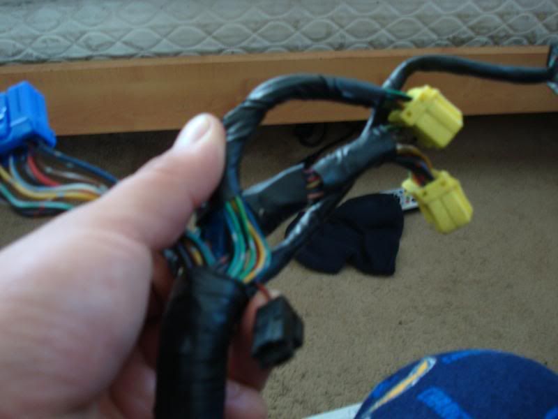
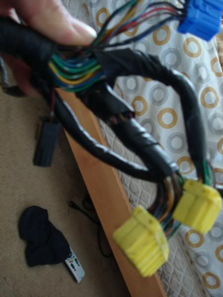
Can anyone tell me what this little black connector is with a single blk/red wire to a connector is? Is that the from the clutch interlock? i dont have this connector on my auto harness.
bump, also in this line...13 - Blue/Green ----------------------- Q .. Neutral
i dont have that color wire coming out of spot 13 on the em manual x-14 conn, all the other wires matched up according to the diagram but this spot is empty on my conn. what should i do with the blue/green wire?
i dont have that color wire coming out of spot 13 on the em manual x-14 conn, all the other wires matched up according to the diagram but this spot is empty on my conn. what should i do with the blue/green wire?

Joined: Nov 2011
Posts: 3,425
Likes: 489
From: okinawa to tampa