
auto to 5spd help *stranded* with a rant..


Thread Starter
Banned. I got OWNED!!!
Joined: Jun 2003
Posts: 1,619
Likes: 0
From: Central Florida
auto to 5spd help *stranded* with a rant..
So im am in the middle of ****ing nowhere hicksville georgia. I took my car towed my car to atlanta because i was told my could would be back on the road.. cool.. I take it up there and after hours of dicking around I have a 5spd harness replacing my auto harness that actually worked on my car.. so now I dunno what the hell to do because I have this 5spd harness on a auto to manual swap and the fkking thing doesnt seam like its going to work at all. I dont have the clutch switch, the 1-2 switch or anything but the actual 5spd swap. Worked fine but i didnt have resistors on my 1600cc injectors on my car so the stupid things hate my pfc and stop working.. The atl guys think its my wiring harness.. so that gets swaped out and it created 500new problems it seams.. what do I do to get my car working again.. im 500+ miles from home at my brothers.. pissed, stressed and want to kill this car..
"I see triangles"
Joined: Apr 2003
Posts: 1,119
Likes: 0
From: PA
https://www.rx7club.com/showthread.p...auto+to+manual
https://www.rx7club.com/showthread.p...06#post2569106
In these is the wiring diagram you need.
https://www.rx7club.com/showthread.p...06#post2569106
In these is the wiring diagram you need.
"I see triangles"
Joined: Apr 2003
Posts: 1,119
Likes: 0
From: PA
Here you go
Looking at the blue X-05 connector, I will describe it as the following:
Manual wires in Auto wires in
1 2 ----- 3 4 ............ A B C D E F------- G H I J K
5 6 7 8 9 10 .............L M N AA BB CC DD EE O P
Hopefully this above lines up properly visually. 1-10 are manual wires and the Auto wires are: A-P small pins, AA-EE large pins. The view is the EM harness from the engine to the dash (looking at the wires entering into the plug). I have taken the manual harness 10 wires and connected to this harness the following way:
COLOR - DESCRIPTION - POSITION IN X-05 AUTO CONNECTOR
Black/Green - magnetic clutch a/p ---- AA
Yellow - 1st gear switch ----------- N Connects to 2K at ECU
Brown/Black - Pressure sensor --------- P
Black/Blue - a/p magnetic clutch ------- K
Brown/White - Pressure Sensor --------- I
Black/Yellow - Injectors --------------------- BB
White/Blue - Cooling Relays -------------- J
Black/White - Solenoid Valves ----------- DD
Red - 2nd gear switch ----------------------- B Connects to 2L at ECU
Black from X-14 wire to X-05 ---------------H
Add Clutch Switch:
1 side to ground, other side connect to G
Add Clutch Interlock:
One side to CC one side to EE - Depressed ON allows starter to work with clutch in only.
Brown from X-05 - Neutral Switch - connect to Yellow at B1-01 EC/AT computer connnection. Connects to 1R at ECU
All other connectors left open with no wire connections.
Also, the X-14 EM connector 1-14 is the pin position of the manual, the A-R is the pins of the Auto EM harness (looking at the wires going into the back of the connector)
Manual wires In Auto Plug Wires In
1 2 3 ---------- 4 5 6 ...............A B C D ---- E F G H
7 8 9 10 11 12 13 14 ...............I J K L M N O P Q R
1 - Orange ------------------------------- I .. Speedo Input
2 - Yellow/Red ------------------------- J .. Rev Light Power to light
3 - Lt Green ---------------------------- Ground .. Neutral
4 - Yellow/White ---------------------- F.. Temp Gauge
5 - Brown/Yellow --------------------- G .. Fuel Thermo Sensor
6-------not used------
7 - Black - Over to X-05 Position H .. Cluster Ground
8 - Green -------------------------------- A .. Speedo Input
9 - Green/Yellow ---------------------- E .. Rev Light Power to Switch
10 - Blue --------------------------------- Ground .. 2nd Gear
11 - White ------------------------------- Ground .. 1st Gear
12 - Black/Yellow (Black/Red?) - P.. H2O thermo fan switch
13 - Blue/Green ----------------------- Q .. Neutral
14 - Yellow ------------------------------ R .. Elect Load input Signal.
Trending Topics

No it's not Turbo'd
Joined: Jun 2002
Posts: 2,511
Likes: 2
From: Los Angeles, Ca
(number1) see now that doesn't help anybody !
I'd wire it to something like the neutral switch on the tranny, or just hardwire it since you "know" better than to start a car that's in gear...
I'd wire it to something like the neutral switch on the tranny, or just hardwire it since you "know" better than to start a car that's in gear...
"I see triangles"
Joined: Apr 2003
Posts: 1,119
Likes: 0
From: PA
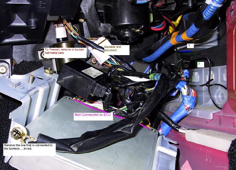
Like it says on that diagram, there is a blue aux connector, besides all the ones that go to the ECU, on the 5 spd harness. And if you look at the auto harness there is also an extra connector, but it is a huge white one. What you need to do is take the pins out of the blue one and stick them in the white auto one, in the right spots, so it'll match the connector under the dash. It makes it totally plug and play.
Hope this helps.
Ryan
Hope this helps.
Ryan
Last edited by Zyon13B; May 2, 2004 at 05:15 PM.
Thread Starter
Banned. I got OWNED!!!
Joined: Jun 2003
Posts: 1,619
Likes: 0
From: Central Florida
is the blue aux connector the small dark blue one? And is the harness I need to make it work on the auto harness still? I dont have the actual auto harness but I still have the peice that kinda goes betweein it that has the large blue connectors as well as white connectors connected to it.. What exactly do I need? I want to get out of georgia...
"I see triangles"
Joined: Apr 2003
Posts: 1,119
Likes: 0
From: PA
Yes use the big white connector from the auto harness(the one that doesn't go to the ECU). Just take all the pins out and slide the pins from the 5spdinto it in the right configuration, the way the diagram says. Use the wires from the blue connector on the 5spd. The you can throw the blue connector away then.
Thread Starter
Banned. I got OWNED!!!
Joined: Jun 2003
Posts: 1,619
Likes: 0
From: Central Florida
I guess im not understanding which connectors.. white ones on auto harness.. so if I dont have the actual engine harness the one that runs into the engine bay im screwed or do I have it if I have the middle harness that plugs between the 2 blue ones and white ones? and which blue on 5spd harness do I use?
Thread Starter
Banned. I got OWNED!!!
Joined: Jun 2003
Posts: 1,619
Likes: 0
From: Central Florida
well where would hte white one normally connect? because I have hte middle peice that connects between engine harness and kinda extends the actual engine harness..
"I see triangles"
Joined: Apr 2003
Posts: 1,119
Likes: 0
From: PA
Scratch that. It's the blue one just to the right and down a bit in the back, it's blue with black around it( also it's a 5spd because the connectors blue and there's no auto tranny ECU) PLus I sorta remember the auto white connector to be a bit wider.