
AEM Tru Boost Gauge Type BC Installation

Thread Starter
Senior Member
iTrader: (1)
Joined: Nov 2005
Posts: 655
Likes: 0
From: Hamilton, Ontario, Canada
AEM Tru Boost Gauge Type BC Installation
Hi everyone.
I have decided to do a writeup with pictures of my installation of the AEM Electronic Boost Controller installation.
I hope I can give a little contribution for those who may need help with this.
There are several installations in the forum, but I didn't see any for the AEM.
Thank you to all those who have done other writeups, your help was vital for the completion of this one.
FORUM Moderators: If you don't believe this thread is interesting or useful enough, please do what you have to do, I'll understand.
DISCLAIMER:
Anything you do is done AT YOUR OWN RISK. I AM NOT AN FD GURU BY ANY MEANS.
If you experts out there feel that there are mistakes, imperfections and corrections to be made and/or feel to pitch in with any kind of suggestion, please chime in at any time, your experience and knowledge will always be happily welcome by me.
The purpose of this writeup is primarily to give enough information to somebody like me, who is not extremely experienced and considers himself a noob.
Situation:
I have a 1993 Canadian FD.
I had installed a mechanical boost gauge.
I carried out the even cheaper bastard air intake mod.
The car has only a DP besides the air intake mod.
I had the turbos swapped for a non oil burning set recently.
Boost pattern was perfect with the previous set (10-8-10).
After the air intake mod, my boost gauge started to go for "walks" past the 10 PSI mark.
After swapping turbos, the same was happening with the new set.
I decided to install a boost controller and go from there.
I decided to purchase an AEM Tru Boost as I liked the fact that it is all included in a gauge. I also found one selling here brand new for a good price, so I purchased it.
I am not looking at making loads of power, so I thought that -at least for the time being- this would be a good solution for my car.
This is a picture of the BC package:

The gauge comes with 2 different backgrounds, two different trim rings and 2 different covers for the two button area. All of them are interchangeable.
I decided to go with silver ring, silver bottom cover and black background. I figured this would stay as close as possible to the stock configuration. If you look at the picture, you can see that the gauge is already setup the way I will go with.
To setup the gauge: the outer trim ring is screwed down. Undo it and carefully remove the bottom cover if you need to do so, then simply drop the other cover on. If you need to change the background: remove the glass carefully, remove the background, remove the bottom cover and drop in the other background; drop the bottom cover and the glass back on, then screw the trim ring in and you're all set.
More to come, I am in the process of doing this.
I have decided to do a writeup with pictures of my installation of the AEM Electronic Boost Controller installation.
I hope I can give a little contribution for those who may need help with this.
There are several installations in the forum, but I didn't see any for the AEM.
Thank you to all those who have done other writeups, your help was vital for the completion of this one.
FORUM Moderators: If you don't believe this thread is interesting or useful enough, please do what you have to do, I'll understand.
DISCLAIMER:
Anything you do is done AT YOUR OWN RISK. I AM NOT AN FD GURU BY ANY MEANS.
If you experts out there feel that there are mistakes, imperfections and corrections to be made and/or feel to pitch in with any kind of suggestion, please chime in at any time, your experience and knowledge will always be happily welcome by me.
The purpose of this writeup is primarily to give enough information to somebody like me, who is not extremely experienced and considers himself a noob.
Situation:
I have a 1993 Canadian FD.
I had installed a mechanical boost gauge.
I carried out the even cheaper bastard air intake mod.
The car has only a DP besides the air intake mod.
I had the turbos swapped for a non oil burning set recently.
Boost pattern was perfect with the previous set (10-8-10).
After the air intake mod, my boost gauge started to go for "walks" past the 10 PSI mark.
After swapping turbos, the same was happening with the new set.
I decided to install a boost controller and go from there.
I decided to purchase an AEM Tru Boost as I liked the fact that it is all included in a gauge. I also found one selling here brand new for a good price, so I purchased it.
I am not looking at making loads of power, so I thought that -at least for the time being- this would be a good solution for my car.
This is a picture of the BC package:
The gauge comes with 2 different backgrounds, two different trim rings and 2 different covers for the two button area. All of them are interchangeable.
I decided to go with silver ring, silver bottom cover and black background. I figured this would stay as close as possible to the stock configuration. If you look at the picture, you can see that the gauge is already setup the way I will go with.
To setup the gauge: the outer trim ring is screwed down. Undo it and carefully remove the bottom cover if you need to do so, then simply drop the other cover on. If you need to change the background: remove the glass carefully, remove the background, remove the bottom cover and drop in the other background; drop the bottom cover and the glass back on, then screw the trim ring in and you're all set.
More to come, I am in the process of doing this.
Thread Starter
Senior Member
iTrader: (1)
Joined: Nov 2005
Posts: 655
Likes: 0
From: Hamilton, Ontario, Canada
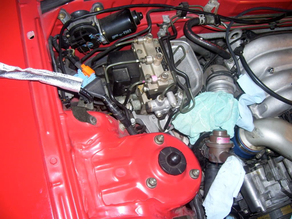
Step One: Have a look under the hood and remove plastics
I decided to plan everything carefully before I would go ahead and do something.
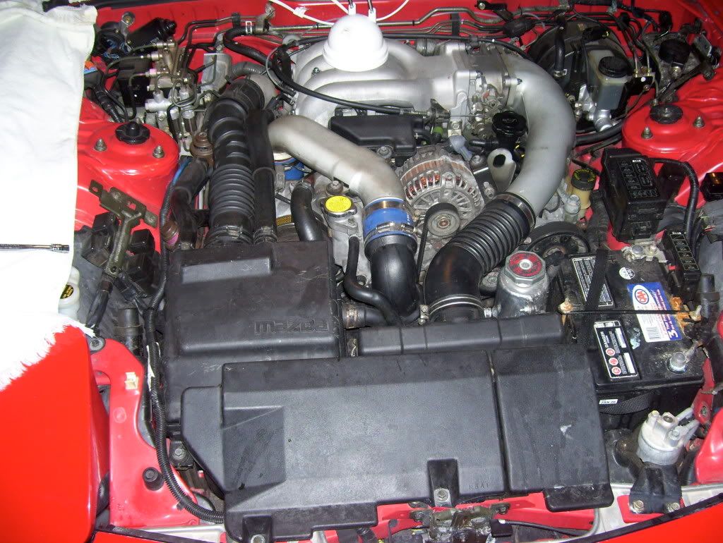
Here's my engine bay:
I decided to re-use the boost line I had already routed in the car for this application. At that time, I poked a hole in the steering column boot/grommet (forgive my ignorance) and I fed the line through there.
I started with removing all the intake system, to get to the Wastegate and the PCA (hope I'm using the right nomenclature, if not, send suggestions in).
The intake shroud is bolted down with 2 10mm bolts located in the front of it. Unscrew those and pull the shroud up.
Next, I removed all the hoses that connect to the upper half of the air filter box. They are all clamped with spring-type clamps. I used a vise-grip to squeeze them and the I pulled them away from their seat using both the vise and a screw driver. I chose to remove some of the hoses while I simply move others out of the way (namely, the BOV hoses)

Once all the hoses were disconnected, I unscrewed the 4 bolts that hold the intake filter box down. 2 are located along the front of it, while there is 1 on the left and 1 on the right. Be careful not to drop the one on the right side as it is pretty deep down.
Every hole left behind by the hoses removal was plugged with rags.
Here's my engine bay:
I decided to re-use the boost line I had already routed in the car for this application. At that time, I poked a hole in the steering column boot/grommet (forgive my ignorance) and I fed the line through there.
I started with removing all the intake system, to get to the Wastegate and the PCA (hope I'm using the right nomenclature, if not, send suggestions in).
The intake shroud is bolted down with 2 10mm bolts located in the front of it. Unscrew those and pull the shroud up.
Next, I removed all the hoses that connect to the upper half of the air filter box. They are all clamped with spring-type clamps. I used a vise-grip to squeeze them and the I pulled them away from their seat using both the vise and a screw driver. I chose to remove some of the hoses while I simply move others out of the way (namely, the BOV hoses)
Once all the hoses were disconnected, I unscrewed the 4 bolts that hold the intake filter box down. 2 are located along the front of it, while there is 1 on the left and 1 on the right. Be careful not to drop the one on the right side as it is pretty deep down.
Every hole left behind by the hoses removal was plugged with rags.
Thread Starter
Senior Member
iTrader: (1)
Joined: Nov 2005
Posts: 655
Likes: 0
From: Hamilton, Ontario, Canada
Step 3 Make decisions
Once I removed all the intake stuff, I was left with a big hollow and a lot of decisions to make.
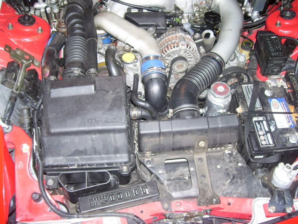
Here's a picture of the engine bay with a simple sketch of where I thought I could place the solenoid:
Please note the "even cheaper bastard intake funnel on the bottom left side of the image.
There are basically 2 things I needed to decide as far as the engine bay part of the installation:
1) Whether or not to install the solenoid in that location;
2) What type of BC hose re-routing to choose between what people around here refer to as version 1 and Version 2
Thread Starter
Senior Member
iTrader: (1)
Joined: Nov 2005
Posts: 655
Likes: 0
From: Hamilton, Ontario, Canada
Solenoid Location and Information
I contacted AEM to ask some information in regards to the solenoid location.
I received promptly 2 responses.
They suggest to not install the solenoid close to a direct source of heat.
After further investigation, they told me that it shouldn't see operating temperatures higher than 105C (221 F).
I am not sure this is good or bad news...
I did some searching on this board and found some underhood temperatures, but they are related to objects under the hood, rather than air within.
https://www.rx7club.com/showthread.p...d+temperatures
The good thing is that the cold side of the turbo was registering 200 F (93c), so the location I would like to use should be cool enough. I am still a bit worried about heat soak upon idling the car or leaving it somewhere after I have driven for a while...
Any info would be appreciated.
I am going to buy some heat reflective material to shield the solenoid and I'll think about install location again, just to see what alternatives I have.
Thread Starter
Senior Member
iTrader: (1)
Joined: Nov 2005
Posts: 655
Likes: 0
From: Hamilton, Ontario, Canada
I should be done by the end of this week. I am taking my time and I am trying to teach my teenage son about this car (and some mechanic work as well)... I hope this will help you.
BTW, if the one in the avatar is your RX7, your car is identical to mine....;-)
BTW, if the one in the avatar is your RX7, your car is identical to mine....;-)
Thread Starter
Senior Member
iTrader: (1)
Joined: Nov 2005
Posts: 655
Likes: 0
From: Hamilton, Ontario, Canada
Solenoid Assembly and some snags...
Solenoid Assembly.
I set off to assemble the connectors into the solenoid.
There are 3 ports in this one and the instructions say that for the installation of the BC in an "internal wastegate" setup, the sintered muffler has to be installed in port three.
I tried to screw the muffler on, but it seems like the screw doesn't want to go in easy after just 1 or 2 turns. So, I decided to hold the metal section of the solenoid with vise-grips, while screwing the muffler in with a 7/16" wrench.
I wrapped the solenoid metal part with some paper to avoid the vise-grip to bite and mark the metal. I also didn't clip the grip on, I rather closed it loose and then used the back nut to gently tighten the vise grip into the solenoid.

Everything worked fine.
At this point, I hit a snag, probably because I am a noob, and I didn't realize this ahead of time...
The connectors that came with the kit and that screw into ports 1 and 2 are smaller than the vacuum hose needed to connect the line from the turbo to the solenoid and the line to the wastegate from the turbo.
So, I am going to go out, purchase the hose needed and also see what I can find to either step to a different size, or find a connector that screws into the solenoid, but is bigger than those supplied with the kit.
As usual, if anybody has any suggestions/ideas/information, chime in at any time.
I set off to assemble the connectors into the solenoid.
There are 3 ports in this one and the instructions say that for the installation of the BC in an "internal wastegate" setup, the sintered muffler has to be installed in port three.
I tried to screw the muffler on, but it seems like the screw doesn't want to go in easy after just 1 or 2 turns. So, I decided to hold the metal section of the solenoid with vise-grips, while screwing the muffler in with a 7/16" wrench.
I wrapped the solenoid metal part with some paper to avoid the vise-grip to bite and mark the metal. I also didn't clip the grip on, I rather closed it loose and then used the back nut to gently tighten the vise grip into the solenoid.
Everything worked fine.
At this point, I hit a snag, probably because I am a noob, and I didn't realize this ahead of time...
The connectors that came with the kit and that screw into ports 1 and 2 are smaller than the vacuum hose needed to connect the line from the turbo to the solenoid and the line to the wastegate from the turbo.
So, I am going to go out, purchase the hose needed and also see what I can find to either step to a different size, or find a connector that screws into the solenoid, but is bigger than those supplied with the kit.
As usual, if anybody has any suggestions/ideas/information, chime in at any time.
Trending Topics
Thread Starter
Senior Member
iTrader: (1)
Joined: Nov 2005
Posts: 655
Likes: 0
From: Hamilton, Ontario, Canada
I honestly didn't try Lowes because it didn't even click into my head. They have opened a store here only recently and I don't even know where it is...
Biggest problem right now, however, is the hose. In Hamilton Ontario so far it has been impossible to find a 6mm rubber/silicone/whatever hose to continue this job...
It is late to call some places now, but I'll try tomorrow and go from there.
Somebody said use 1/4", but this is about .4 mm larger diameter, I don't think it's the right way to do it...
Thread Starter
Senior Member
iTrader: (1)
Joined: Nov 2005
Posts: 655
Likes: 0
From: Hamilton, Ontario, Canada
A fellow Canadian has sent me a PM (I posted a request for a hose place nearby in the Canadian Forum) and I'll call this place tomorrow.
What type of hose should I exactly ask for? Pressure, Vacuum, High heat...
Last edited by gio64; Nov 19, 2008 at 09:01 PM.
Yeah thats mine...hopefully I will have time to install some stuff soon.
Thread Starter
Senior Member
iTrader: (1)
Joined: Nov 2005
Posts: 655
Likes: 0
From: Hamilton, Ontario, Canada
Well, I usually hope that I have enough tools and ability to do the job...
I would say you're a couple of steps ahead of me as far as that goes.
But GL with the install, so far, the hardest things seem to have been dealing with finding certain parts. However, my job seems to be much easier because I had already wired and plumbed a boost gauge prior to this.
I would say you're a couple of steps ahead of me as far as that goes.
But GL with the install, so far, the hardest things seem to have been dealing with finding certain parts. However, my job seems to be much easier because I had already wired and plumbed a boost gauge prior to this.
Thread Starter
Senior Member
iTrader: (1)
Joined: Nov 2005
Posts: 655
Likes: 0
From: Hamilton, Ontario, Canada
Solenoid Prepped
I have been working bit by bit, but I have been busy to post.
So, the line coming off the turbo is 6mm and the one into the solenoid has a barb fitting that is smaller. I decided to purchase two fitting to replace those that came with the solenoid, so that I could run a hose from the turbo line to the solenoid and back out to the wastegate.
To prepare the solenoid:
Use teflon tape on the threads
Find a way to keep the solenoid from moving while you screw the fittings in (I used vise grips tightening them using the bolt on them rather than squeezing the solenoid).
Install the fitting.
Please note: the fittings ends are tapered, so they won't screw all the way in unless you really force the two parts together. As long as the fitting is tightened, you'll be fine.
Here's a pic of the solenoid prepped and ready to go:
Thread Starter
Senior Member
iTrader: (1)
Joined: Nov 2005
Posts: 655
Likes: 0
From: Hamilton, Ontario, Canada
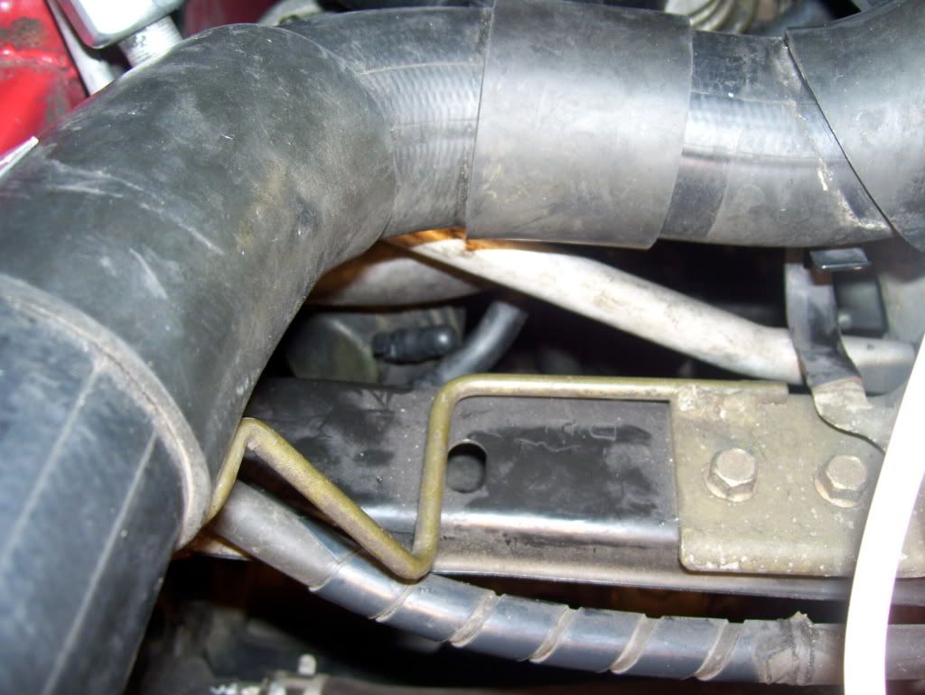
Where am I going to put the darn solenoid?
Here's what I spent 2 hours on yesterday:
WHERE THE HELL AM I GOING TO PUT THE SOLENOID?
I had made a thread in this respect. Mahjik was nice enough to give me a couple of hints.
I had picked a location, which on paper seems to be great, but, once I put the hoses into the solenoid, I realized that there is no room in that area to place it.
So, I recall reading a thread where somebody has placed it right beside the strut tower, on the bracket that holds... Other solenoid? I am not sure what those are, forgive the noob.
It seems to be a decent place, but what I don't particularly like about it is the fact that the hoses from the turbo and to the wastegate are very long. As far as I have understood this, shorter lines=better response, so I would like to place it a bit closer to the ends.
Realistically, the only other location is right behind the air filter box. There is however a bit of an issue with the fact that it ends up touching both those metal lines (one big and one small) that run from the fender side down the front (I am not sure what they are). Once again, chime in if you have any ideas. I'll keep thinking.

Thread Starter
Senior Member
iTrader: (1)
Joined: Nov 2005
Posts: 655
Likes: 0
From: Hamilton, Ontario, Canada
Naturally, I'll have the opportunity to raise that later, once I upgrade support systems (fuel, ECU, cooling and IC).
But right now, my only intent is to keep boost at 10-8-10 and be able to drive the car reliably. Everything else will have to wait a bit.
Thread Starter
Senior Member
iTrader: (1)
Joined: Nov 2005
Posts: 655
Likes: 0
From: Hamilton, Ontario, Canada
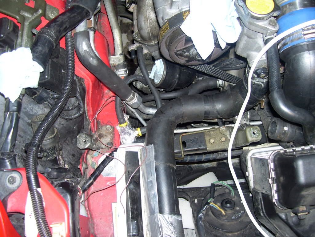
Solenoid Location... At last???
Well, I spent some more time in my garage trying to decide where would be good to put the solenoid.
Although there are a few spots, it seems that they all have a problem. I even thought of placing it behind the Air Intake box! No space. Wherever I try, there always is either a pipe, or something that makes it less than ideal or next to impossible to do. The stupid size of the barb connectors and the protruding muffler don't make it any easier either.
For those who don't have an "even cheaper bastard intake" mod, there should be plenty of room where the funnel is installed. I kind of like that area because it is not too short and it is not too hot.
After cursing last evening and this morning, I had a bit of a revelation.
The primary turbo intake duct is not there, so there is another obstacle I didn't account for last night to make things even more difficult.
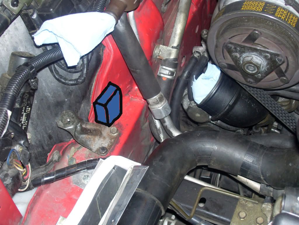
However, I believe that the location I marked in the picture below should do it.
It fits under the intake box, the hoses don't need particularly sharp curves, they are not too long, they don't rub against anything really, and the place is not too hot.
I realize there is the rad hose there, but I am going to wrap the solenoid with heat reflective/insulating stuff.
Any input would be really really appreciated.
Although there are a few spots, it seems that they all have a problem. I even thought of placing it behind the Air Intake box! No space. Wherever I try, there always is either a pipe, or something that makes it less than ideal or next to impossible to do. The stupid size of the barb connectors and the protruding muffler don't make it any easier either.
For those who don't have an "even cheaper bastard intake" mod, there should be plenty of room where the funnel is installed. I kind of like that area because it is not too short and it is not too hot.
After cursing last evening and this morning, I had a bit of a revelation.
The primary turbo intake duct is not there, so there is another obstacle I didn't account for last night to make things even more difficult.
However, I believe that the location I marked in the picture below should do it.
It fits under the intake box, the hoses don't need particularly sharp curves, they are not too long, they don't rub against anything really, and the place is not too hot.
I realize there is the rad hose there, but I am going to wrap the solenoid with heat reflective/insulating stuff.
Any input would be really really appreciated.
Thread Starter
Senior Member
iTrader: (1)
Joined: Nov 2005
Posts: 655
Likes: 0
From: Hamilton, Ontario, Canada
Wiring and Boost Controller lines secured
Before securing the solenoid I finalized the location of both the boost controller line going into the cabin and the electrical line going from the cabin to the solenoid.
As stated before, they both go through the steering column boot.

I used black zip ties to hold them in place; do not choke the the boost controller pressure line.

I wrapped the last part of the wire with heat reflective/insulating material
As stated before, they both go through the steering column boot.
I used black zip ties to hold them in place; do not choke the the boost controller pressure line.
I wrapped the last part of the wire with heat reflective/insulating material
Thread Starter
Senior Member
iTrader: (1)
Joined: Nov 2005
Posts: 655
Likes: 0
From: Hamilton, Ontario, Canada
Installing the hoses
OK.
It was bloody freezing here for at least 5 days in a row.
Now, maybe for some other Canadians and some of you down south this is nothing special, but I lived in Italy 30 years and this is no way to end a November, at least where I am from...
So, now that my garage is accessible again, I did some more things.
I took the vacuum lines going to the stock solenoids out and then I started the "plumbing" for the "version Sweet" that I am going to try first.
Version sweet is pretty much like version 2, but it has a few less feet of hoses and -as far as I can tell- it seems to be obtaining the exact same objective.
So, I capped the line "out" of the PCA (hopefully I don't make mistakes with names here).
I put a hose from the "out" of the wastegate to the "in" of the PCA.
I capped one of the two turbo lines.
I went from the other turbo line nipple to the "in" in the solenoid.
I went from the "out" of the solenoid to the "in" of the wastegate.
I wrapped the solenoid with reflective material.
I need to zip tie the lines from the solenoid and the capped line at the turbo.
Tomorrow I'll wire it up and go to work in the car.
I should be able to start her up again by Thursday.
Any screw-up you see, please let me know.
Thread Starter
Senior Member
iTrader: (1)
Joined: Nov 2005
Posts: 655
Likes: 0
From: Hamilton, Ontario, Canada
Solenoid Located
Finally, I managed to place the solenoid where I wanted it.
You can see it at the bottom, right against the even cheaper bastard funnel all wrapped up with reflective material. The wires are wrapped as well.

Once again, I have used the "version sweet" system.
I put everything back together in the intake area.
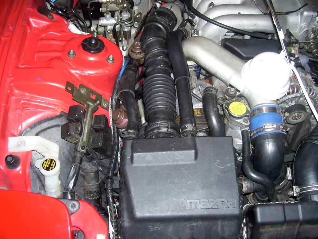
Now I need to cap the boost control solenoid and fix the plug I damaged while taking things off the car.
You can see it at the bottom, right against the even cheaper bastard funnel all wrapped up with reflective material. The wires are wrapped as well.
Once again, I have used the "version sweet" system.
I put everything back together in the intake area.
Now I need to cap the boost control solenoid and fix the plug I damaged while taking things off the car.
Thread Starter
Senior Member
iTrader: (1)
Joined: Nov 2005
Posts: 655
Likes: 0
From: Hamilton, Ontario, Canada
OK, I forgot to take a couple of pictures to better explain this one.
I removed the vacuum tank to access the 2 solenoids that needed to be capped.
They are located under the UIM, but right at the front edge of it.
By removing the vacuum tank, I managed to get enough room to do what I had to.
I unplugged both solenoids, the plugs have a little tab. By squeezing the tab and pulling it should come undone easily.
I used a flat head screw driver to gently pull the two top vacuum hoses (one per solenoid) out.
I replaced the hoses with 2 caps and I zip-tied the caps. The space is very slim (surprise surprise...) and I had to use needle nose pliers to push the caps in and to pull the zip ties tight.
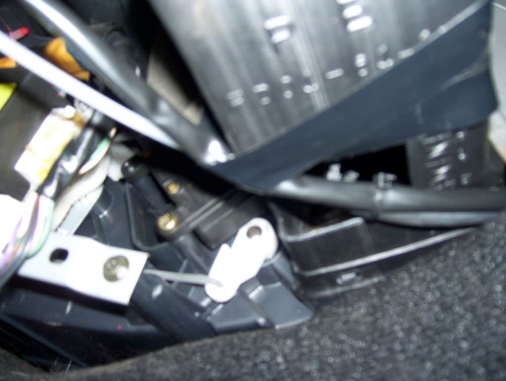
Here's a picture of the vacuum tank re-installed. If you look hard, you can see the line capped on the closest solenoid.

The cap is the first rubber element you can see under the gas pedal wire. You can also see a bit of the green of one of the solenoids.... Sorry about this one again...
I removed the vacuum tank to access the 2 solenoids that needed to be capped.
They are located under the UIM, but right at the front edge of it.
By removing the vacuum tank, I managed to get enough room to do what I had to.
I unplugged both solenoids, the plugs have a little tab. By squeezing the tab and pulling it should come undone easily.
I used a flat head screw driver to gently pull the two top vacuum hoses (one per solenoid) out.
I replaced the hoses with 2 caps and I zip-tied the caps. The space is very slim (surprise surprise...) and I had to use needle nose pliers to push the caps in and to pull the zip ties tight.
Here's a picture of the vacuum tank re-installed. If you look hard, you can see the line capped on the closest solenoid.
The cap is the first rubber element you can see under the gas pedal wire. You can also see a bit of the green of one of the solenoids.... Sorry about this one again...
Thread Starter
Senior Member
iTrader: (1)
Joined: Nov 2005
Posts: 655
Likes: 0
From: Hamilton, Ontario, Canada
Wires and Vacuum Cabin Setup
I finally managed to go to work in the cabin again.
Like I said, I used the original hard white plastic line to get through the firewall.
I decided to carry the white hard line from the firewall right to the back of the dash
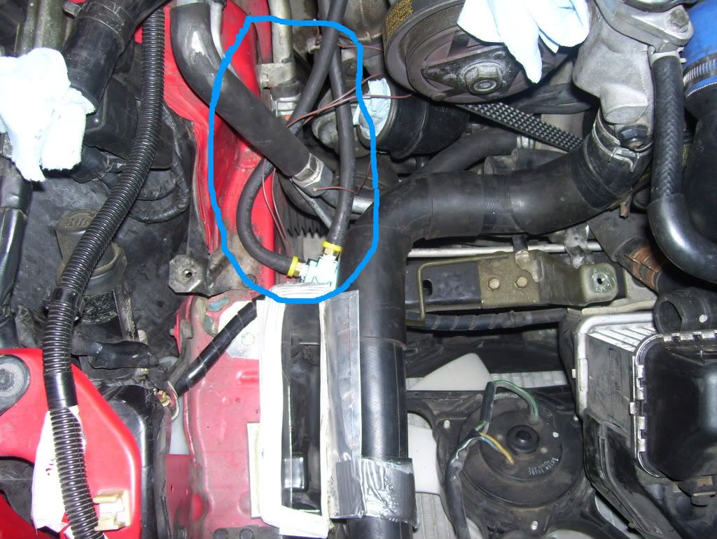
Here's the picture of the vacuum line secured out of the firewall
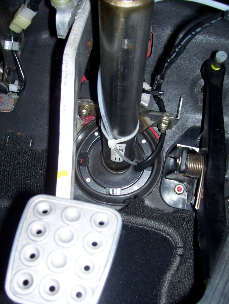
Since the line is pretty hard, I decided to make it gently bend around the steering column and over it, to avoid kinking it.
Here's a picture of the vacuum line tied with the electrical line

And here's a picture of it taped to the left vent right behind the dash.
This is where I connected another section of rubber vacuum line to the white hard line to get to the back of the gauge.
I'll change the tape with a zip tie, I ran out of the big ones for this one.
Here's a shot of the rubber vacuum line coming out of the back of the dash.
Like I said, I used the original hard white plastic line to get through the firewall.
I decided to carry the white hard line from the firewall right to the back of the dash
Here's the picture of the vacuum line secured out of the firewall
Since the line is pretty hard, I decided to make it gently bend around the steering column and over it, to avoid kinking it.
Here's a picture of the vacuum line tied with the electrical line
And here's a picture of it taped to the left vent right behind the dash.
This is where I connected another section of rubber vacuum line to the white hard line to get to the back of the gauge.
I'll change the tape with a zip tie, I ran out of the big ones for this one.
Here's a shot of the rubber vacuum line coming out of the back of the dash.
Thread Starter
Senior Member
iTrader: (1)
Joined: Nov 2005
Posts: 655
Likes: 0
From: Hamilton, Ontario, Canada
Side tracked... My worst weakness
Hi everyone (again). I didn't give up.
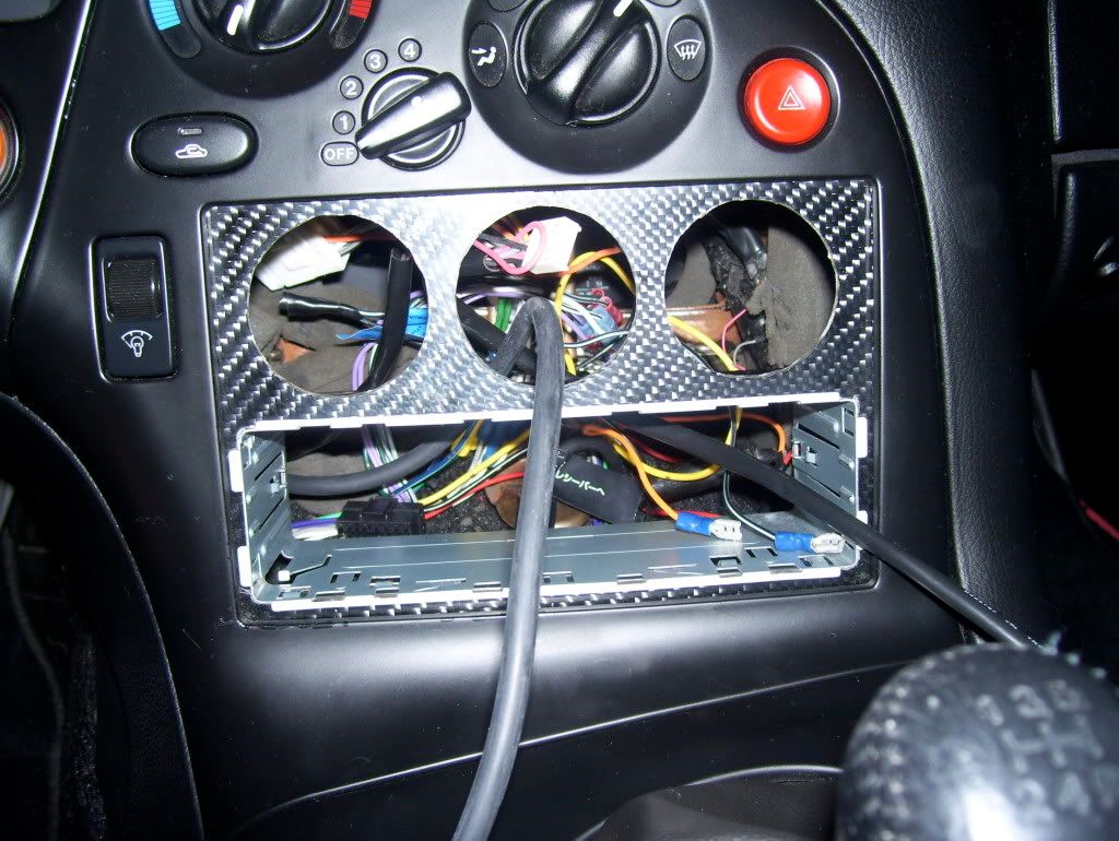
I decided that -since I was taking things apart- I was going to remove the instrument cluster and the AC panel to change all the light bulbs.
The removal went well and it was inspired by the fact that I wanted to have better access to the area where I was working.
I need to get the AC panel bulbs from Mazda, since I don't know what the number is and none of those I purchased thinking they would be the same, were all about .5 mm too large, rendering it impossible to stick the light mount back in the hole.
I took the opportunity to fix both the temperature and the "flow director" (for lack of a better name), in the AC Panel. If I would turn the heat/cooling back and forth, it would have a spongy feel and only engage at the end of the run. Similar but less evident problem was displayed by the "flow director".
Once I took the AC panel out and I removed the dials, I found out what the problem was: both the dials act on a rotating switch that is connected to a small circuit board. The connection between the rotating switch and the back side of the mounting hole (right behind the dial) is secured by a shallow nut/washer that threads into the outer part of the shaft where you press in the dial. Both my nuts (...) were loose, so the dial would spin free until it would be held by the wires attached to it, at which point it would hold the switch still and the switch would do its job (hence the weird/spongy feel to it). I took the nuts off (...), I put some thread locking compound on them and re-tightened the nuts in place, easy/cheap fix that has given me a "new" AC panel set of controls.