AEM Tru Boost Gauge Type BC Installation

Thread Starter
Senior Member
iTrader: (1)
Joined: Nov 2005
Posts: 655
Likes: 0
From: Hamilton, Ontario, Canada
Back to the AEM BC
So, while waiting until tomorrow morning to call Mazda and get the damn bulbs, I continued to work on the BC installation.
I had the "in cabin" part of the work to do.
First of all, the wire loom is made of two sections. One goes from the engine bay to the cabin, while the other is just in the cabin.
This one has 5 wires: one is the positive from the engine bay (that bypasses the plug that goes in the controller); one is the ground; one is the positive for the BC unit in the car; one is grey and it is intended to connect a overboost warning light to the system; one is orange and it is used to activate the "scramble boost" function.
You can see the plug and some of the wires in this image
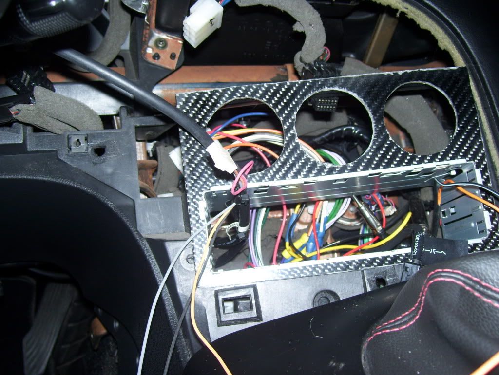
I decided that I was going to ground, place the warning light and possibly the scramble boost switch somewhere near the centre console, so I extracted the wires from the in cabin loom to separate them from the two positives.
I fed the loom out the back of the centre console, over the steering column and down the side beside the driver side footrest.
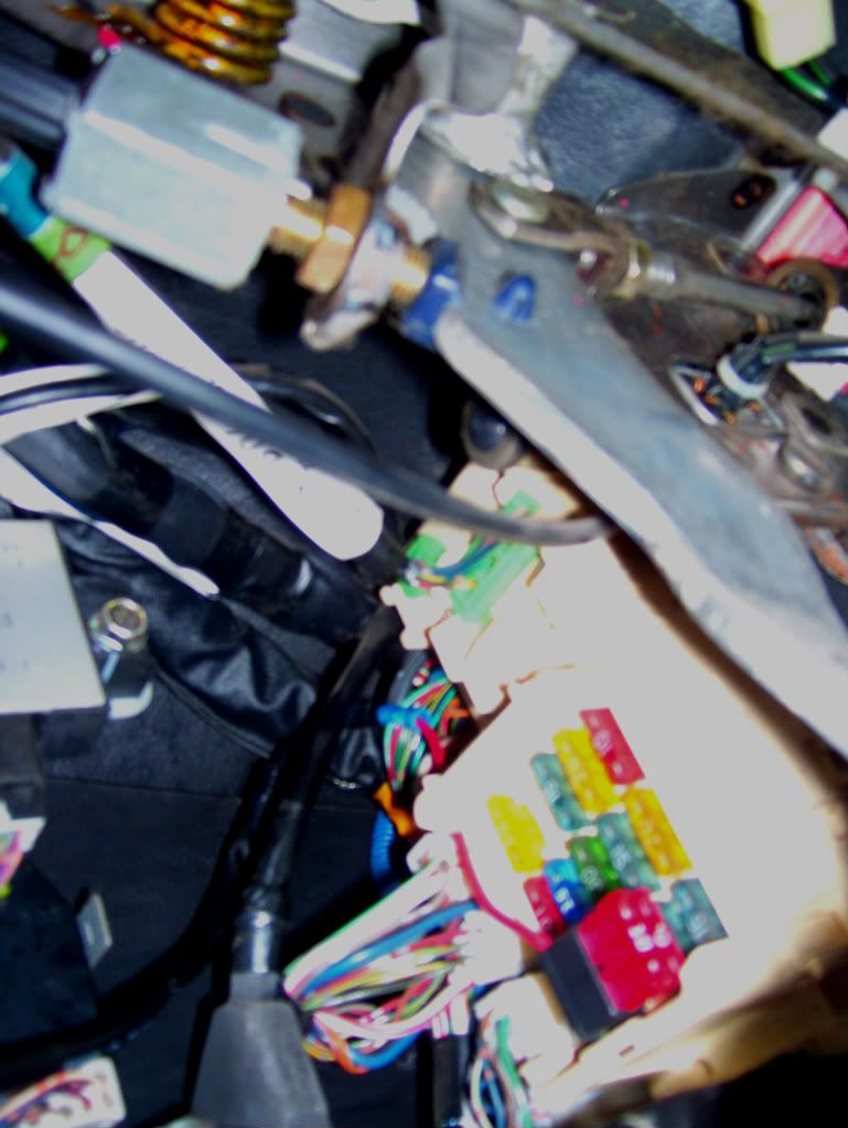
I purcased a splitter at Canadian Tire, which is basically a plug that goes in the place of a fuse and splits the line in two: one is the original, which receives its original fuse, the other is for the extra device you need to wire.
I pulled the radio fuse and plugged the splitter in there with 2 10A fuses on it. I then crimped both the positive wires I had just fed through to the extra line.
If anybody has any problems with this and wants to add suggestions, you are welcome.
I believe this should not cause any problems and the installation is clean.
The only thing this could cause is extra load on the wire that comes into the fuse box from the ignition.
Here's an image of the installation:
I secured the loom to other wires I found on my way there, making sure it doesn't rattle or shake anywhere and it has no chance to get in the way of my feet.
I also zip tied both the looms together behind my CF gauge panel, to make sure they would not be moving and tugging on the single wires.
I had the "in cabin" part of the work to do.
First of all, the wire loom is made of two sections. One goes from the engine bay to the cabin, while the other is just in the cabin.
This one has 5 wires: one is the positive from the engine bay (that bypasses the plug that goes in the controller); one is the ground; one is the positive for the BC unit in the car; one is grey and it is intended to connect a overboost warning light to the system; one is orange and it is used to activate the "scramble boost" function.
You can see the plug and some of the wires in this image
I decided that I was going to ground, place the warning light and possibly the scramble boost switch somewhere near the centre console, so I extracted the wires from the in cabin loom to separate them from the two positives.
I fed the loom out the back of the centre console, over the steering column and down the side beside the driver side footrest.
I purcased a splitter at Canadian Tire, which is basically a plug that goes in the place of a fuse and splits the line in two: one is the original, which receives its original fuse, the other is for the extra device you need to wire.
I pulled the radio fuse and plugged the splitter in there with 2 10A fuses on it. I then crimped both the positive wires I had just fed through to the extra line.
If anybody has any problems with this and wants to add suggestions, you are welcome.
I believe this should not cause any problems and the installation is clean.
The only thing this could cause is extra load on the wire that comes into the fuse box from the ignition.
Here's an image of the installation:
I secured the loom to other wires I found on my way there, making sure it doesn't rattle or shake anywhere and it has no chance to get in the way of my feet.
I also zip tied both the looms together behind my CF gauge panel, to make sure they would not be moving and tugging on the single wires.
Thread Starter
Senior Member
iTrader: (1)
Joined: Nov 2005
Posts: 655
Likes: 0
From: Hamilton, Ontario, Canada
Thread Starter
Senior Member
iTrader: (1)
Joined: Nov 2005
Posts: 655
Likes: 0
From: Hamilton, Ontario, Canada
Warning Light Wiring
Alright.
I purchased a very simple round red light at "Performance Improvements", here in Hamilton. Mostly a muscle car performance place, but they do have some things that are interesting to me.
The light has obviously 2 wires. The way the AEM BC controls it, is by grounding the negative (grey in the supplied wire loom attached to the plug that goes in the back of the controller, one of the wires I took out).
So, I picked the positive I had disconnected from my previous mechanical boost gauge and I used it for the warning light. It is actually a dimmed source, but I figured I have never in my life dimmed the lights down to zero and I really doubt I will be going to do this while driving the snot out of my baby, so this should be fine.
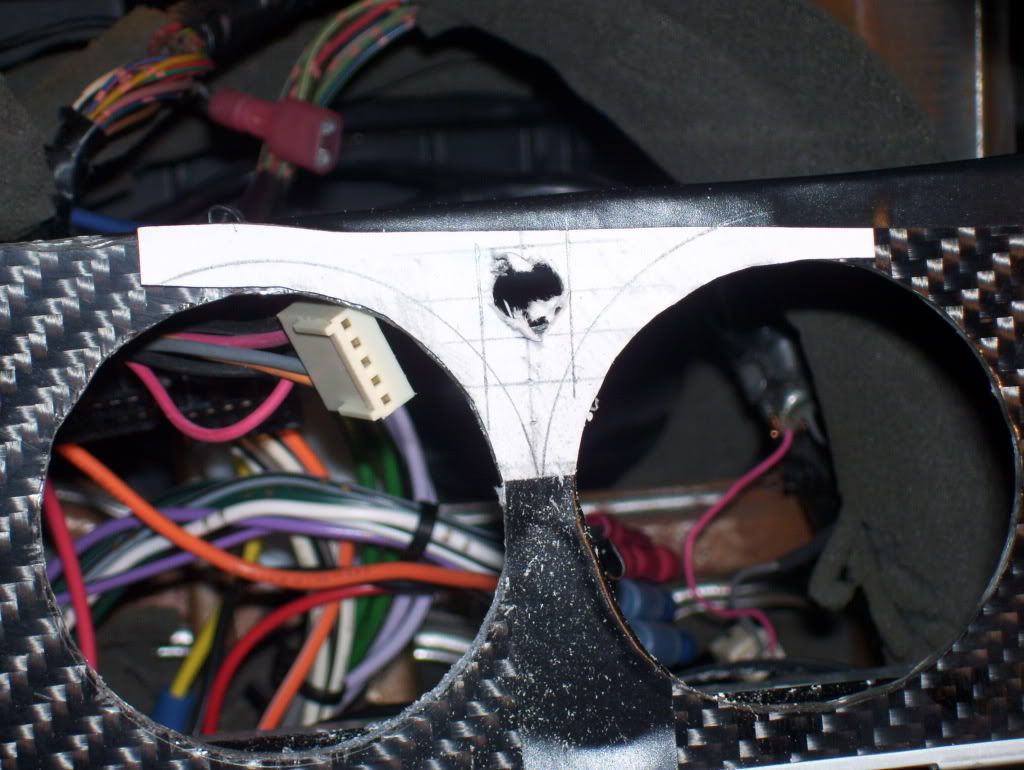
Before wiring the little sucker, I had to put a hole somewhere to locate it.
Now, I'm sure everyone will have something to say, but I didn't want to drill anything that "mother" Mazda placed in the inside of this car (at least nothing visible), so I decided to place the light to the right of the gauge. Not really in front of my eyes, but certainly "catchable" if it goes off while I drive.
To do this, I traced the gauges holes on a small piece of paper, I cut the template after designing the middle line and marking 5mm intervals on it, I marked the trim ring of the gauge and I placed the template where it belonged, so I could exactly drill out a hole.
The image is dim, but in any other way, my pencil work wouldn't show.
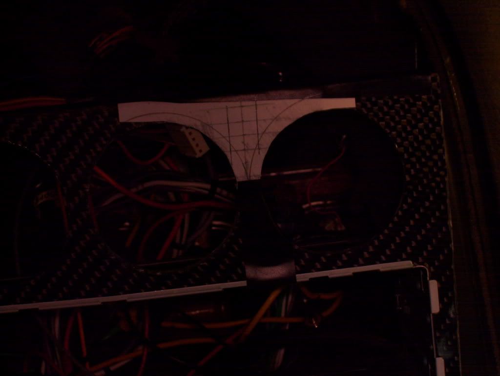
I drove a small bit in first, then I put a 5/16" in and bored the right size hole (the light says 5/16" on it).
Cleaned it all up:
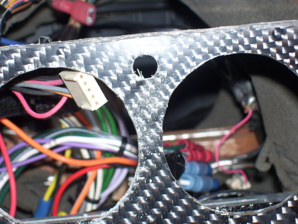
I fed the two wires through the hole, connected them with the warning light wires, pushed everything back in to complete the job.
I purchased a very simple round red light at "Performance Improvements", here in Hamilton. Mostly a muscle car performance place, but they do have some things that are interesting to me.
The light has obviously 2 wires. The way the AEM BC controls it, is by grounding the negative (grey in the supplied wire loom attached to the plug that goes in the back of the controller, one of the wires I took out).
So, I picked the positive I had disconnected from my previous mechanical boost gauge and I used it for the warning light. It is actually a dimmed source, but I figured I have never in my life dimmed the lights down to zero and I really doubt I will be going to do this while driving the snot out of my baby, so this should be fine.
Before wiring the little sucker, I had to put a hole somewhere to locate it.
Now, I'm sure everyone will have something to say, but I didn't want to drill anything that "mother" Mazda placed in the inside of this car (at least nothing visible), so I decided to place the light to the right of the gauge. Not really in front of my eyes, but certainly "catchable" if it goes off while I drive.
To do this, I traced the gauges holes on a small piece of paper, I cut the template after designing the middle line and marking 5mm intervals on it, I marked the trim ring of the gauge and I placed the template where it belonged, so I could exactly drill out a hole.
The image is dim, but in any other way, my pencil work wouldn't show.
I drove a small bit in first, then I put a 5/16" in and bored the right size hole (the light says 5/16" on it).
Cleaned it all up:
I fed the two wires through the hole, connected them with the warning light wires, pushed everything back in to complete the job.
Thread Starter
Senior Member
iTrader: (1)
Joined: Nov 2005
Posts: 655
Likes: 0
From: Hamilton, Ontario, Canada
On to the Controller
One more step to get me closer to the end of the project.
I pulled the vacuum/boost hose out of the hole I chose for the BC.
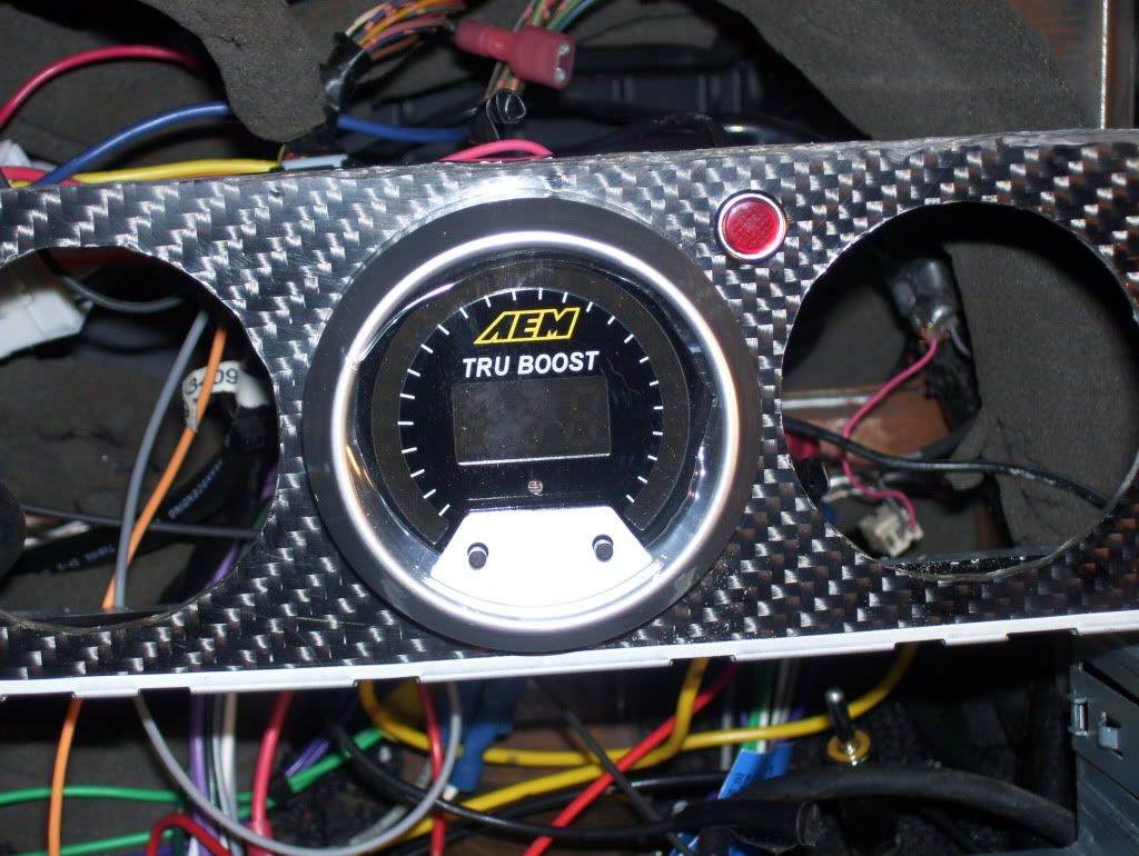
I trimmed it to the desirable length; I decided to put a "T" in it, so -at least for the time being, while I set and check the EBC- I'll have the possibility of getting readouts from my mechanical gauge. I read that the electronic one is a bit difficult to read precisely, so I figured I'll have this back up plan. I placed a rubber hose on each side of the "T"; I zip-tied each end; I hooked and zip-tied a section of the original plastic hose that came with my mechanical boost gauge (I have then decided that I'll just hook up a different fitting to the back of the gauge, so I can simply go with rubber only behind the dash; I'll go buy a female 1/8" barb tomorrow, put it in and be done with it.
In the picture you can see both the "T" node and the warning light installed.
Once this was ready, I simply plugged the rubber open end out of the "T" in the back of the AEM EBC; I pushed the plug in, then pushed the EBC in place. I made sure I didn't force anything, especially considering that the instructions say not to tug on the short rubber hose coming out of the back of the EBC unit.
I finally got the rear bracket and the two nuts that go with it, placed it and tightened it in the back of the EBC to complete this part of the job.
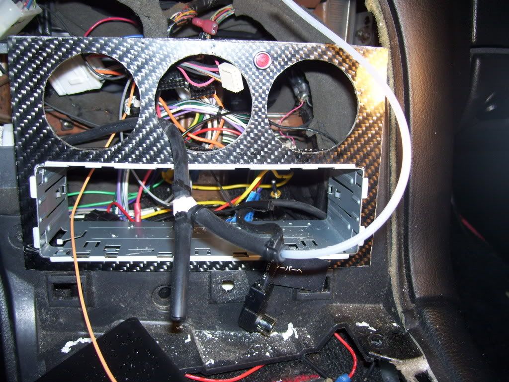
Last step for tonight: I reinstalled the stereo in. I figured that this way I had clearance to push the wires and the hoses out of the way, so everything would be in nicely.
I did that and this is the result:
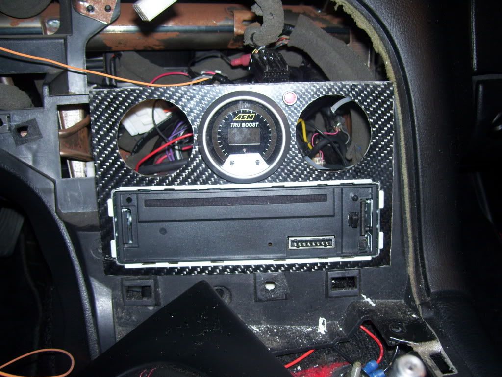
Hopefully, tomorrow I'll get the lights and the fitting, so I can complete the installation, reinstall the AC Panel, the Instrument Cluster and fire it up to make sure everything is good.
I pulled the vacuum/boost hose out of the hole I chose for the BC.
I trimmed it to the desirable length; I decided to put a "T" in it, so -at least for the time being, while I set and check the EBC- I'll have the possibility of getting readouts from my mechanical gauge. I read that the electronic one is a bit difficult to read precisely, so I figured I'll have this back up plan. I placed a rubber hose on each side of the "T"; I zip-tied each end; I hooked and zip-tied a section of the original plastic hose that came with my mechanical boost gauge (I have then decided that I'll just hook up a different fitting to the back of the gauge, so I can simply go with rubber only behind the dash; I'll go buy a female 1/8" barb tomorrow, put it in and be done with it.
In the picture you can see both the "T" node and the warning light installed.
Once this was ready, I simply plugged the rubber open end out of the "T" in the back of the AEM EBC; I pushed the plug in, then pushed the EBC in place. I made sure I didn't force anything, especially considering that the instructions say not to tug on the short rubber hose coming out of the back of the EBC unit.
I finally got the rear bracket and the two nuts that go with it, placed it and tightened it in the back of the EBC to complete this part of the job.
Last step for tonight: I reinstalled the stereo in. I figured that this way I had clearance to push the wires and the hoses out of the way, so everything would be in nicely.
I did that and this is the result:
Hopefully, tomorrow I'll get the lights and the fitting, so I can complete the installation, reinstall the AC Panel, the Instrument Cluster and fire it up to make sure everything is good.
Thread Starter
Senior Member
iTrader: (1)
Joined: Nov 2005
Posts: 655
Likes: 0
From: Hamilton, Ontario, Canada
Almost there...
Here I am again.
I was waiting to get the lights for the AC panel before I would complete the install.
Tonight I have put the other two gauges back in place (they are both temporary and one of them (the A/F ratio) is purely a hole plug.
The boost gauge however is functional. I plumbed the plastic hard line in the back and pushed it in place. As you recall, I had put a "T" into the rubber vacuum hose coming in for the AEM BC. So this boost gauge is hooked to the other side of the "T".
I dusted everything, plugged everything back in place and tested all electrical connections before I snapped the panel back in place and screwed it back in.
Here's a picture of the result:
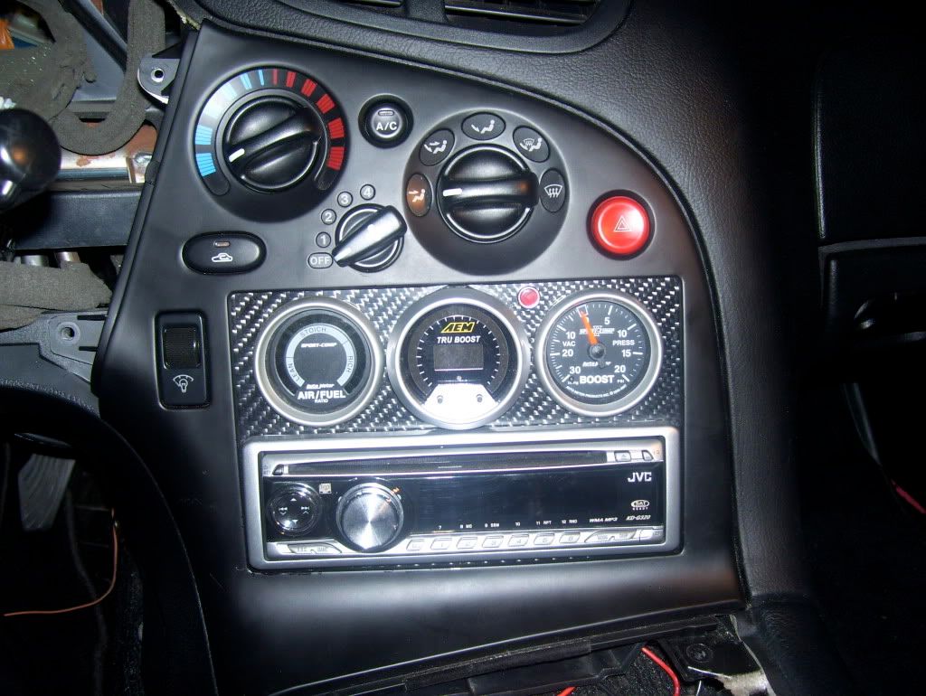
I did hit a snag. The fuse I had pulled to install the splitter was not switched. I decided to move the connection to the sunroof fuse, which it switched. Now everything is fine. The BC starts up and goes trough a "boot procedure", then it says: "Off".
Now the only thing left is the installation of the "Scramble Boost" switch and the reinstallation of the instrument cluster and the other plastics I had to remove to get to it.
I was waiting to get the lights for the AC panel before I would complete the install.
Tonight I have put the other two gauges back in place (they are both temporary and one of them (the A/F ratio) is purely a hole plug.
The boost gauge however is functional. I plumbed the plastic hard line in the back and pushed it in place. As you recall, I had put a "T" into the rubber vacuum hose coming in for the AEM BC. So this boost gauge is hooked to the other side of the "T".
I dusted everything, plugged everything back in place and tested all electrical connections before I snapped the panel back in place and screwed it back in.
Here's a picture of the result:
I did hit a snag. The fuse I had pulled to install the splitter was not switched. I decided to move the connection to the sunroof fuse, which it switched. Now everything is fine. The BC starts up and goes trough a "boot procedure", then it says: "Off".
Now the only thing left is the installation of the "Scramble Boost" switch and the reinstallation of the instrument cluster and the other plastics I had to remove to get to it.
Thread Starter
Senior Member
iTrader: (1)
Joined: Nov 2005
Posts: 655
Likes: 0
From: Hamilton, Ontario, Canada
Installation Phase Completed
Hi everyone.
Just to let anyone interested know: I completed the installation (as you could see in the thread) and I have also re-installed everything back in place.
Today, taking advantage of the dry weather and clean streets, I took the car out to have a look at what is going on (I only drove around the subdivision to avoid to get unwanted salt on it).
Here's the deal: the BC is working fine. It is keeping the boost at 7 psi on the primary. I did a couple of touch-ups on the settings, but I really cannot do anything specific at the moment, as I need to go on an open road and start getting it where it's supposed to be.
For now, at least no boosting past 10 (in fact, as I said, it is at 7).
There seems to be a clear discrepancy between the reading on the EBC boost level and the mechanical boost gauge (autometer) that I had.
At idle, the EBC reads roughly 18 and the other reads 20. When I step on it, the EBC shows about 6.8 and the gauge reads about 8.
They are hooked up to the same line that splits right behind the dash.
Any ideas/suggestions?
I finally managed to go to work in the cabin again.
Like I said, I used the original hard white plastic line to get through the firewall.
I decided to carry the white hard line from the firewall right to the back of the dash
Here's the picture of the vacuum line secured out of the firewall
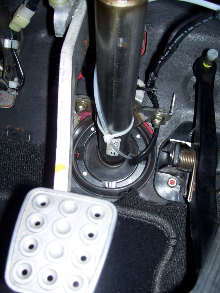
Since the line is pretty hard, I decided to make it gently bend around the steering column and over it, to avoid kinking it.
Like I said, I used the original hard white plastic line to get through the firewall.
I decided to carry the white hard line from the firewall right to the back of the dash
Here's the picture of the vacuum line secured out of the firewall
Since the line is pretty hard, I decided to make it gently bend around the steering column and over it, to avoid kinking it.
Thread Starter
Senior Member
iTrader: (1)
Joined: Nov 2005
Posts: 655
Likes: 0
From: Hamilton, Ontario, Canada
When I installed my boost gauge I tried to go that route but I had a terrible time trying to get to the grommet you mentioned and so at some point I gave up. Since I found that some people had used the steering boot, I installed there. This time around, I already had the hole to go through, so I didn't redo that part.
I agree with what you said in regards to the "professionality" of the installation in the grommet you mentioned.