
AEM IGN-1A Mercury Marine ignition coil info/install
 03-24-12, 03:18 PM
#1
AEM IGN-1A Mercury Marine ignition coil info/install
I originally went with a HKS Twin Power like most people because of how easy it is to use and install plus there are a good amount of people going pretty far with them. Had I known about these and how simple it could be to put them in I would have gone this route from the beginning. I have a GT35R and at 17 psi with just water on wannaspeeds preturbo water injection set up I was getting ignition break up on the dyno. This was with the HKS, NGK 10.5x4, 8.5 magnacore wires. I really want 20 psi straight water and as much as the kit will deliver. I figure this will work from what I've read, we'll see........
So I'm still putting my car together but wanted to make this and post my progress as I make it. I didn't find all the info I was looking for on the forum so I'm hoping other people will help compile any useful info here so people have the info they need to decide if they are right for them.
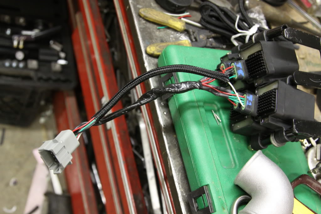
First here's a shot of my working space and the coils themselves, it's my friend's garage that owns the red 2JZ FD there.
So I'm still putting my car together but wanted to make this and post my progress as I make it. I didn't find all the info I was looking for on the forum so I'm hoping other people will help compile any useful info here so people have the info they need to decide if they are right for them.
First here's a shot of my working space and the coils themselves, it's my friend's garage that owns the red 2JZ FD there.
 03-24-12, 03:26 PM
#2
Harness
I bought everything from C. Ludwig here on the forum. I asked him if he could make me as close of a plug and play set up as possible and this is the harness I received. I'm extremely happy I had asked because this thing is way better than what I would have done on my own. Everything is labeled and all I needed to do was hook up 4 wires then power and ground. Here are pics of the harness itself.
03-24-12, 03:40 PM
#3
How easy it really is to install
Here are the 4 wires you need to connect after cutting off the stock igniter plug. The 3 wires that I didn't use I just put tape over individually then shrink tubed together.
Wiring connections:
Stock New Ignition
Light Green Green/Black
Brown Green/Red
Brown/Black Green/Brown
Black/White Yellow
Wiring connections:
Stock New Ignition
Light Green Green/Black
Brown Green/Red
Brown/Black Green/Brown
Black/White Yellow
03-24-12, 03:49 PM
#4
Soldered & shrink tubed
Seriously, this is pretty damn easy to hook up if you go the lazy route like me and purchase the harness to go with it. The black/white wire that connects to the yellow wire is thicker than the rest if you notice in the pictures, I don't personally know why.
03-24-12, 04:04 PM
#6
But I only hooked up 4 wires, I thought these were all for the internal ignitors? I'm running power from the battery to the relay with an inline fuse.
Also, I was wondering about the 2 ground wires. The paperwork from AEM says to ground one to the engine and one to the battery. Can't I just ground both to the battery since both the engine and battery have grounds to the body of the car?
Also, I was wondering about the 2 ground wires. The paperwork from AEM says to ground one to the engine and one to the battery. Can't I just ground both to the battery since both the engine and battery have grounds to the body of the car?
03-24-12, 04:24 PM
#7
Wastegate John
iTrader: (13)
Join Date: Feb 2008
Location: Long Island NY 11746
Posts: 2,979
Likes: 0
Received 9 Likes
on
9 Posts
I am assuming you are using a pfc? If so there are only 3 coil trigger wires because the oem system has only 3 coils. You still need a switched 12 volt source to trigger the relay.
I think Chris may want you to ground one wire to each rotor housing. That is how Chris told me to wire mine up. However that may depend on how the wire harness was made up.
I think Chris may want you to ground one wire to each rotor housing. That is how Chris told me to wire mine up. However that may depend on how the wire harness was made up.
Trending Topics
03-24-12, 07:16 PM
#9
I gotta bug my buddy with the red FD for the fab work. I'm thinking of something to hold the coils out front and the water injection tank. Should fit with my turbojeff battery tray.
I'll post pics and updates as I make progress. I'd like to see what other people have done.
I'll post pics and updates as I make progress. I'd like to see what other people have done.
03-26-12, 04:02 PM
#12
RENESISFD has it nailed. The stock black/white wire is a power feed to the stock ignitor. 12V+ is fed to the coils through this wire, so it's a heavy gauge. We're just using it for a turn on signal for the relay in the new harness. Amp draw is minimal, so the yellow wire is 20g. The high current for the coils comes through the red wires in your harness that connect directly to the battery, through the fuse and relay.
The PFC is a 3-channel ECU. The leading coils will fire together is wastespark, just like the stock system. The advantage of the Mercury coils in this configuration is that they require a relatively low charge time to produce a strong spark. 3ms will net around 115mj. We can run them at around 4.5ms in wastespark and produce a stronger spark than an LS truck coil will make at 6.0ms. If you ever change ECUs, it's will be possible to run the coils in a 4-channel sequential mode. Since you're not really dwell limited with the PFC and wastespark, there's not a great rush to change.
Matt, there should just be one ground lug in your harness. Since it was convenient to the construction of the harness, I ran everything back to the negative terminal of the batter. These coils have 3 pins on the connector that are all used for grounding. The idea, in the OE configuration, is that the various grounds are used for power and misfire detection. In the aftermarket application, all 3 pins can be grounded to the same place. The rotor housing or cylinder head is a good location, since the block should have a very good connection to the negative terminal of the battery. Grounding directly to the battery negative terminal also works well. I would not use a chassis ground.
The following users liked this post:
Akaviri (04-05-21)
03-26-12, 04:56 PM
#13
Awesome, thanks for the info. That's exactly what I'm looking to get in this thread. I want people to be able to look here and see how easy it can be to switch to these. I love how simple it is with the harness you made for me. I'm about to head to the garage now and try and come up with some ideas for mounting. If you have any pics of these mounted to show some options please feel free to post them here.
03-29-12, 11:19 AM
#14
Wastegate John
iTrader: (13)
Join Date: Feb 2008
Location: Long Island NY 11746
Posts: 2,979
Likes: 0
Received 9 Likes
on
9 Posts
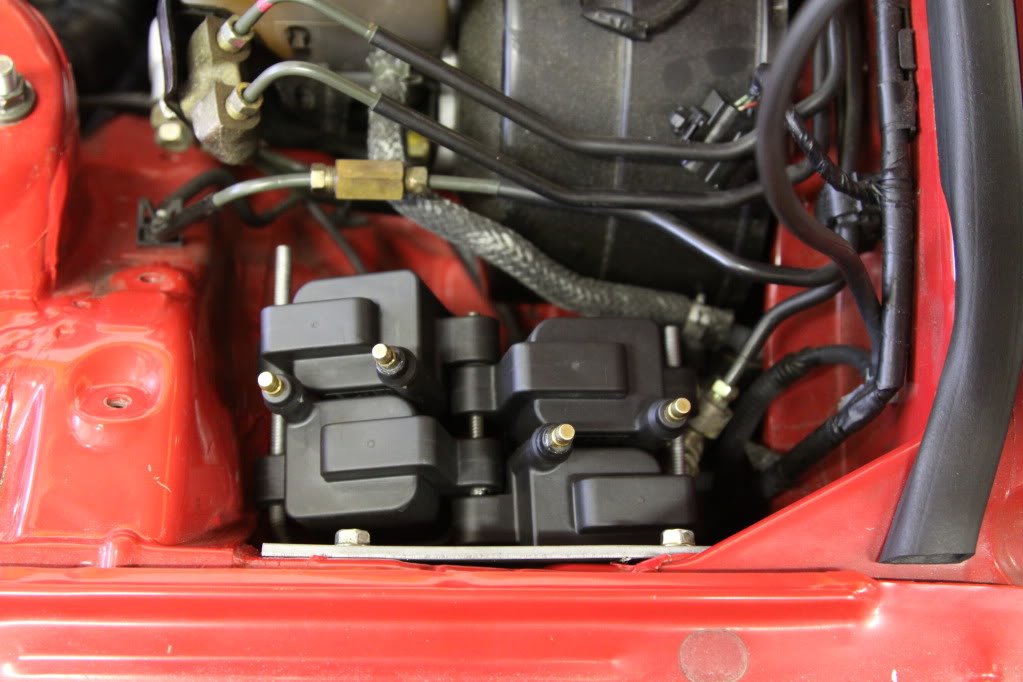
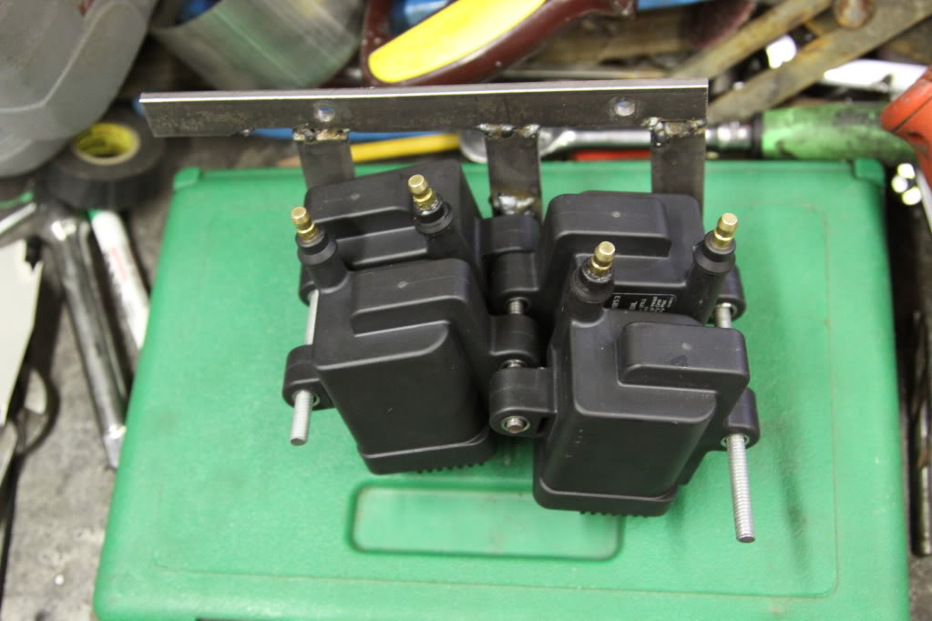
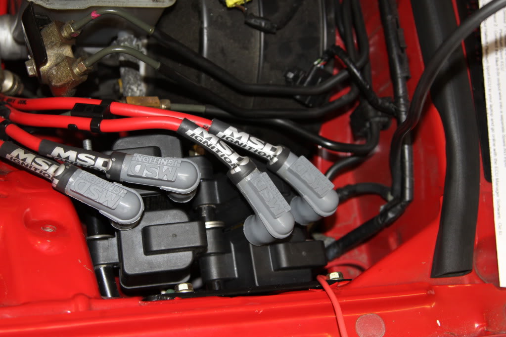
Here are some pics of my coils mounted. You will notice that they are mounted on an angle. That is so that they clear the shock tower.
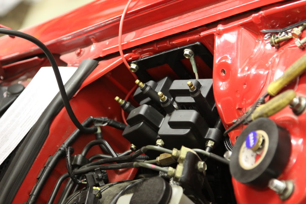
Test fitting. Don't mind the crappy welds i fixed them on the finished bracket.
John
Test fitting. Don't mind the crappy welds i fixed them on the finished bracket.
John
04-25-12, 12:32 PM
#16
Wastegate John
iTrader: (13)
Join Date: Feb 2008
Location: Long Island NY 11746
Posts: 2,979
Likes: 0
Received 9 Likes
on
9 Posts
^ These coils really pump out some spark. On the way down to deals gap I had an ID 2000 secondary stick open . The car would not run on the rear rotor because of this. We pulled the fuel pump fuse and with a few seconds of craking the car was running on the excess fuel in the rear rotor housing. There was literally raw fuel dripping out of my exhaust. I did not have to do a deflood procedure inorder to start the car. So far I am very happy with them.
Right now my car is making 400WHP with AI at 15psi and the coils show no signs of ignition issues.
John
. The car would not run on the rear rotor because of this. We pulled the fuel pump fuse and with a few seconds of craking the car was running on the excess fuel in the rear rotor housing. There was literally raw fuel dripping out of my exhaust. I did not have to do a deflood procedure inorder to start the car. So far I am very happy with them.Right now my car is making 400WHP with AI at 15psi and the coils show no signs of ignition issues.
John
04-29-12, 12:59 PM
#17
I need to get my car put back together and back on the dyno. I found out that for some reason, I've had insanely high EGT's. I had my exhaust manifold slightly modified to fit my Turblown LIM and turbine housing heat shields. While doing this I found my exhaust manifold had zero carbon in it and my turbine blade was melting. I'm hoping to finish putting it back together and on the dyno in the next couple weeks. I've also been hoping to get my headlights back from Sakebombgarage and my new seats before driving it so I've been moving slow.
 04-29-12, 02:16 PM
#19
Wastegate John
iTrader: (13)
Join Date: Feb 2008
Location: Long Island NY 11746
Posts: 2,979
Likes: 0
Received 9 Likes
on
9 Posts
^ No the point of these coils is to eliminate the stock system including the igniter and to eliminate the need for a twin power.
These coils are an aftermarket system in and of itself.
These coils are an aftermarket system in and of itself.
04-30-12, 09:45 AM
#21
Wastegate John
iTrader: (13)
Join Date: Feb 2008
Location: Long Island NY 11746
Posts: 2,979
Likes: 0
Received 9 Likes
on
9 Posts
I dont really understand what you are asking..... You want to run an ignition amplifier to help increase the output even more?
This is taken from lms-efi.com
"Very excited to announce that we now have a source for the IGN and IGN-1A Mercury Marine ignition coils! AEM is rebadging these coils and offering them under their name. We'll have the IGN (no internal ignitor) and the IGN-1A (built-in ignitor) priced at $55 and $72 respectively. These coils are HOT! 103 mJ output compared with an M&W CDI's 115 mJ output!"
BTW, Thats not me in my avatar
04-30-12, 09:49 AM
#22
Yes, increase the output as long as it doesn't cause premature life at the coil. I have some nice "boards" that can produce 135mj and are the size of a piece of bread. Maybe I'll give Jarad an experiment for half price.
I know it's not you. Only Rich winks at people when he eats... lol
I know it's not you. Only Rich winks at people when he eats... lol
04-30-12, 10:07 AM
#23
Wastegate John
iTrader: (13)
Join Date: Feb 2008
Location: Long Island NY 11746
Posts: 2,979
Likes: 0
Received 9 Likes
on
9 Posts
Do you really think they need to be cranked up? I was very impressed with them at the rest stop. As you saw, raw fuel was coming out of my exhaust but the plugs still fired. No need for deflooding of the engine.
04-30-12, 01:00 PM
#25
Wastegate John
iTrader: (13)
Join Date: Feb 2008
Location: Long Island NY 11746
Posts: 2,979
Likes: 0
Received 9 Likes
on
9 Posts
Yes you can, But you can only go so far. The amount of dwell time directly correlates to your desired maximum RPM.
Basically if the dwell time is too long the coil may not fire when it is supposed to because the engine is spinning too fast. What that RPM is on a rotary; I do not know. The maximum dwell time is 9.0ms allowed by the literature printed on the coils.
Also, there must be some limitation I would not think you can make your dwell time too long and the coil continually will put out more power.
And yes, I am sure C. ludwig would know.